Table of Contents
Advertisement
Quick Links
1. IMPORTANT SERVICE NOTES ........................................................................................................ 2
2. SPECIFICATIONS .............................................................................................................................. 6
3. PART NAMES .................................................................................................................................... 7
4. DISASSEMBLY OF THE SET ............................................................................................................ 8
5. MECHANISM ADJUSTMENT JIGS AND PARTS ............................................................................ 12
ITEMS AND INTERVALS ................................................................................................................. 13
7. ADJUSTING AND CHECKING OF MECHANISM ........................................................................... 14
8. ADJUSTMENT OF RUNNING SYSTEM .......................................................................................... 17
(DISASSEMBLING AND ASSEMBLING) ........................................................................................... 19
10.METHOD OF ADJUSTING THE ELECTRIC CIRCUIT .................................................................... 29
11.USEFUL TIPS ................................................................................................................................... 47
12.SIGNAL FLOW DIAGRAMS ............................................................................................................. 48
13.BLOCK DIAGRAMS ......................................................................................................................... 51
14.SCHEMATIC DIAGRAMS ................................................................................................................ 58
15.SEMICONDUCTOR LEAD IDENTIFICATION ............................................................................... 122
16.PRINTED WIRING BOARD ASSEMBLIES .................................................................................... 124
17.REPLACEMENT PARTS LIST ....................................................................................................... 141
18.PACKING OF THE SET ................................................................................................................. 161
SHARP CORPORATION
SERVICE MANUAL
LIQUID CRYSTAL DISPLAY CAMCORDER
MODEL
In the interests of user-safety (Required by safety regula-
tions in some countries) the set should be restored to its
original condition and only parts identical to those specified
be used.
CONTENTS
This document has been published to be used for
after sales service only.
The contents are subject to change without notice.
1
VL-Z1U
S53B2VL-Z1U//
NTSC
VL-Z1U
Page
Advertisement
Table of Contents

Related Manuals for Sharp VL-Z1U


Summary of Contents for Sharp VL-Z1U
-
Page 1: Table Of Contents
VL-Z1U SERVICE MANUAL S53B2VL-Z1U// LIQUID CRYSTAL DISPLAY CAMCORDER NTSC VL-Z1U MODEL In the interests of user-safety (Required by safety regula- tions in some countries) the set should be restored to its original condition and only parts identical to those specified be used. -
Page 2: Important Service Notes
VL-Z1U 1. IMPORTANT SERVICE NOTES connections, metal cabinet, screw heads, knobs and BEFORE RETURNING THE VIDEO CAMERA control shafts, etc.) and measure the AC voltage drop RECORDER across the resistor. Reverse the AC plug (a non polarized adaptor plug must be used but only for the... - Page 3 VL-Z1U WARNING :TO REDUCE THE RISK OF FIRE OR ELECTRIC SHOCK, DO NOT EXPOSE THIS APPLIANCE TO WET LOCATIONS. CAUTION CAUTION RISK OF ELECTRIC SHOCK DO NOT OPEN This symbol mark means following. Camcorder only For continued protection against fire haz- CAUTION: TO REDUCE THE RISK OF ELECTRIC ard, replace only with same type fuse.
- Page 4 1-800-8-BATTERY or your local recycling center. If you are located outside the United States, contact your local authorities for information concerning proper disposal and/ or recycling of this battery. SHARP’s involvement in this program is part of our commitment to protecting our environment and conserving natural resources.
- Page 5 VL-Z1U I PRECAUTIONS FOR USING LEAD-FREE SOLDER 1) Employing lead-free solder "Main PWB", "CCD PWB", "Sub PWB", "LCD PWB", "Head amp PWB", "Lithium PWB", "Operation PWB", "VCR Operation PWB", "Zoom SW PWB", "Mecha Reversion detection PWB", of this model employs lead-free solder. The LF symbol indicates lead-free solder, and is attached on the PWBs and service manuals.
-
Page 6: Specifications
Specifications are subject to change without notice. SERVICE INFORMATION (For the U.S.) For the location of the nearest Sharp Authorized Service, or to obtain product literature, accessories, supplies or customer assistance, please call 1-800-BE SHARP (1-800-237-4277) or visit SHARP's website (http://www.sharpusa.com) -
Page 7: Part Names
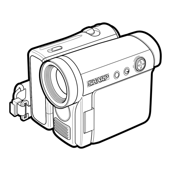
VL-Z1U 3. PART NAMES Front view Operation button Zoom lens DISPLAY button Monaural microphone LCD LAMP button Left view Right view Power Zoom Wide angle/ Window cleaning cover Telephoto control / PHOTO button VOLume control Viewfinder STANDBY indicator STANDBY button... -
Page 8: Disassembly Of The Set
VL-Z1U 4. DISASSEMBLY OF THE SET 4-1. Procedure for disassembling the cabinet Note: Before removing the cabinet, turn OFF the power and make sure that the battery is not connected. · Remove the lens hood and remove the screw ((s) XiPSF14P06000). - Page 9 VL-Z1U Mechanism reversion detection PWB unit Camera top cover Connector PWB mounting angle Camera unit FPC(3) FPC(2) FPC(1) · Remove the screw ((x) LX-HZ0050TAFN), screw ((p) LX- · Remove the screw ((b) XiPSN17P03000) and remove the HZ0063TAFN) and screw ((a) XiPSN17P02000), disconnect Mechanism reversion detection PWB unit.
- Page 10 VL-Z1U 4-2. Procedure for disassembling the cabinet · Remove the three screws ((e) XiPSF17P03000) , remove the screw ((d) XiPSF17P02000) and remove the VCR bottom cover. VCR bottom cover · Remove the two screws ((e) XiPSF17P03000) and remove the tilt cover.
- Page 11 VL-Z1U · Disconnect the six FPCs of the head amp circuit board Mechanism unit. · Remove the two screws ((a) XiPSN17P02000) and remove the head amp PWB unit. · Remove the three screws ((w) LX-BZA022WJFN) and remove the screw ((k) LX-BZA023WJFD).
-
Page 12: Mechanism Adjustment Jigs And Parts
VL-Z1U Sketch 1. Name 5. MECHANISM ADJUSTING JIGS AND PARTS 2. Part code 3. Code 5-1. Mechanism checking and adjusting jigs <Note: Order of descriptions> * Model number and usage 1. Tension gauge 4N 1. Dial tension gauge 1. Cassette torque 1. -
Page 13: Inspection And Maintenance Items And Intervals
VL-Z1U 6. INSPECTION AND MAINTENANCE ITEMS AND INTERVALS In order to maintain the quality of the mechanism section, perform the following maintenance and inspection. After repairing the mechanism section, perform the following maintenance regardless of the number of hours of use by the user. -
Page 14: Adjusting And Checking Of Mechanism
VL-Z1U 7. ADJUSTING AND CHECKING OF MECHANISM The items described here are relevant to the general on-site servicing (field service). This section does not cover adjustment and replacement for which sophisticated equipment, jigs and techniques are required. In order to maintain the initial characteristics of the mechanism, it is necessary to perform maintenance and inspection and also it is essential not to damage the tape etc. - Page 15 VL-Z1U 7-4. Checking and adjusting of tension pole position during Tension pole position (Based on drum base outside shape) REC (PB) 3 to 4V DC, Cassette controller assembly not installed (Mechanism only) 0±0.3 Drum base (1) Checking T pole Check that the tension pole is located in the prescribed position as shown in Fig.4 at the start of a 60-minute tape.
- Page 16 VL-Z1U 7-7. Checking of loading back tension 3 to 4V DC, Cassette controller assembly not installed (Mechanism only) (1) Apply 3 to 4V DC to the loading motor and select the L start mode. (See 9-1.) (2) Move the swing arm to the S reel table side. At this time, take care not to damage the gears etc.
-
Page 17: Adjustment Of Running System
VL-Z1U 8. ADJUSTMENT OF RUNNING SYSTEM 8-1. Outline of adjustment of running system (Replacement parts) · Tu guide and arm Readjustment of height · Slide chassis Preparations for Final adjustment Coarse adjustment adjustment of Installation of of Running system of Running system... - Page 18 VL-Z1U 8-4. Coarse adjustment of running system (Cassette controller installed) 1. Adjustment of height of Su and Tu guide rollers <Method and description> Inlet side Outlet side (1) Play back the alignment tape for running system adjustment and make adjustment so that the inlet ±1/4 shift...
-
Page 19: Assembling Of Mechanism Section And Part Replacement (Disassembling And Assembling)
VL-Z1U 9. ASSEMBLING OF MECHANISM SECTION AND PART REPLACEMENT (DISASSEMBLING AND ASSEMBLING) This section describes the method of assembling the mechanism section and the method of part replacement. For how to remove the cabinet etc., refer to " 4. DISASSEMBLY OF THE SET". - Page 20 VL-Z1U (5) PB (Record, Fast forward, Fast rewind, VSF and VSR) mode This mode is used for playback, recording, fast-forwarding, fast -rewinding, VSF and VSR. In this mode, the pinch roller is pressed against the capstan shaft and the S main brake is located away from the S reel table.
- Page 21 VL-Z1U Fig.7 Fig.8 9-3. Method of operating on the circuit board with the cassette controller assembly removed If this method is performed improperly, the tape may be damaged. Therefore do not use this method except in special cases such as measuring the VSR torque. Be sure to follow the cautions shown in this manual.
- Page 22 VL-Z1U 9-4. Phase-adjust Phase-adjust the following parts. (1) Mode SW (2) Main cam (3) Sub cam (The main cam and sub cam should be also phase-adjusted for the chassis.) (4) S loading arm (5) Tu loading arm (6) Loading drive gear (main cam, sub cam, S loading gear) Note) Check the marker position carefully before disassembling.
- Page 23 VL-Z1U 9-5. Assembling method 9-5-1. Method of assembling the main chassis assembly Note) For reference, numbers are prefixed to parts names to show the sequence of assembly. (For the greasing/oiling and cleaning locations, refer to the diagram of greasing/oiling locations.)
- Page 24 VL-Z1U 9-5-2. Method of assembling the slide chassis assembly (8)Guide nut (6)Tu guide flange (7)Tu guide (14)Tu reel table ass'y (13)S reel table ass'y (1)Slide adjustment (2)T-SPR adjustment (6)Tu guide flange (11)T main brake (5)Guide adjustment SPR (4)Tu guide arm...
- Page 25 VL-Z1U 9-5-3. Method of combining the main chassis assembly and the slide chassis assembly (1) Position the assemblies as shown in the figure below (the pole base is slightly protruded). (2) Insert the operation pins (tension arm, Tu guide arm) of the slide chassis assembly into the locations of the main chassis assembly shown in the figure below, fit the SL drive lever pin of the main chassis assembly into the groove of the slide chassis (the groove of the slide adjustment ANG), and then fix with the two screws.
- Page 26 VL-Z1U 9-5-4. Diagram of greasing/oiling locations...
- Page 27 VL-Z1U 9-6. Method of installing the cassette controller (2)Completed cassette controller (1)Main slide Left side view Right side view ass'y (3)Down guide Right side view Left side view B-1,2 Left side view Right side view (4)Cassette cover Right side view...
- Page 28 VL-Z1U 9-7. Method of taking out the cassette with the mechanism operating singly (1) Apply 3 to 4V DC to the loading motor for slight unloading. (2) If the tape is slack, turn the rotor (mechanism backside) of the capstan motor by hand to take up the slack in the tape.
-
Page 29: Method Of Adjusting The Electric Circuit
401YC: Manufactured by Leader) · Frequency counter 90ADDVC-TAPE (color bar) · Oscilloscope · AC adapter · Error rate adjustment tape (reference tape) RTPEVA001WJZZ VL-Z1U Specifications of service jigs Price New/ Connection section Connector REF. No. No. of pins Parts cord Cont. - Page 30 VL-Z1U VL-Z1U Service jig configuration...
- Page 31 VL-Z1U [TEST POINT] (Wiring board diagram: Main Side A) TL3304 TL3302 L917 L916 L918 SC3301 SC3302 TL902 C974 C973 TL3310 TL913 R3321 Q908 C3321 C975 C3320 IC706 Q911 X702 R990 C980 R932 Q703 C728 R754 R749 R768 TL901 C711 C709...
- Page 32 VL-Z1U (Wiring board diagram: LCD Side A) TL803 TL9801 TL847 TL9805 TL848 R810 R827 R826 TL835 TL9804 R811 TL9802 C818 R825 SC9800 C9805 Q801 Q800 TL9803 TL9800 C821 TL850 R805 TL846(LCD_VG) R809 TL849 C816 C810 C809 LCD_contrast TL853 TL845 TL802...
- Page 33 VL-Z1U [Execution of adjustment] Adjustment of servo and system controller 1. System code setting It is necessary to set the following data items after replacing IC705 (E PROM). <Adjusting method> Select the VCR adjustment mode and set the data value at each address.
- Page 34 VL-Z1U 3. Adjustment of shutdown Mode VCR adjustment mode Adjusting 1) Set a recordable tape and select the camera mode. 2) Press "CONTINUE" → "TEST SEL" on the adjustment remote control to enter the TEST mode (T-01 flashing). method 3) Select T-03 with the FF and REW keys and press "PB" key.
- Page 35 VL-Z1U ADJUSTMENT OF VIDEO I/O CIRCUIT SYSTEM (Envelope checkup TP jig) PCO D/A-Y PCO D/A-C 1. Adjustment of PCO D/A-Y Measurement point (On envelope checkup TP jig) Address VCR ADJ 566 Mode EE mode 1Disconnect the DC cable or battery from the unit.
- Page 36 VL-Z1U 2. Adjustment of VF_COM amplitude (Main PWB) Measurement point TL8801(VF_COM) Address VCR ADJ 32 Procedure 1) Set the data value at address 5EB (TESTSW2) to 77. 2) Connect the digital voltmeter to TL8801 (VF_COM). At address 32 (VF_DAC_C), adjust the DC voltage to the adjustment rating.
- Page 37 VL-Z1U 2. Adjustment of DAC full scale (Main PWB) Measurement point TL6807(G OUT) Address VCR ADJ 094(G) Mode VCR AV input Adjusting method 1) Set the data values at addresses 41E/086/41C and 410 to FF/80/77 and 00, respectively. (The LED shows nothing.) 2) Set the data values at addresses 096/411 and 0A8 to 00/80 and 48, respectively.
- Page 38 VL-Z1U ADJUSTMENT OF MIC AMP CIRCUIT (Wiring board diagram: Sub Side A) (Wiring board diagram: Sub Side B) TL3601(INT MIC L) TL1472 Checking of EE level Checking of EE level Checking of f characteristics Checking of f characteristics C553 C573...
- Page 39 1. Connect with the EUI48/64 ID code control system. (1) Start the Internet Explorer or Netscape Navigator. (2) Access the following address.(URL: http://www.rcg.kami.sharp.co.jp/quics/index.html) Select "EUI48/64 ID code control system" among the "Service" items. Note: If you want to establish a connection by directly inputting the URL, please input the following.
- Page 40 VL-Z1U (5) Click on [Repair use]. Click (6) Input the necessary information for the application. Be sure to input the necessary input items. Select the [Group/company] and [Kind name] from the list. Input the [Model name] in half-size characters. Input the [Serial number] in half-size characters.
- Page 41 VL-Z1U 10.2. Adjustment of camera section 10-2-1. Servicing of camera section (1) Camera adjustment should be performed with the set completed. (2) Subjects, measuring instruments and jigs necessary for servicing and adjustment of the camera section • Gray scale chart •...
- Page 42 VL-Z1U 3) Description of remote control keys "FF" key: It is used to increase the address value and data value. "REW" key: It is used to decrease the address value and data value. "PLAY" key: It is used to confirm the selected address to call up the data. It is also used to confirm the data value.
- Page 43 VL-Z1U (4) Camera signal system adjustment mode In the camera signal system adjustment mode, the auto white balance function is stopped in order to adjust the camera. In this mode, the white balance is set to the indoor mode and focussing is performed manually.
- Page 44 VL-Z1U 10-2-4. Adjusting procedure Adjustment method Item (1) Adjustment of auto focus The following adjustments are performed automatically by establishing the auto focus adjustment mode and writing the following data at address "13FD" sequentially. The adjustment items are as shown in the table below. When an adjustment is completed normally, data "FF"...
- Page 45 VL-Z1U Item Adjustment method (4) Rough adjustment of iris AE 1) While shooting the gray scale normally, observe the video output using the oscilloscope. • Measurement terminal: By rewriting the data at address "0002", adjust the white luminance signal level to S terminal luminance signal output 720±10mVp-p and the gray luminance signal level (on the gray scale background) to...
- Page 46 VL-Z1U Adjustment method Item 1) Perform the adjustment of white balance repeatedly. (7) Adjustment of white balance • Measurement terminal: EE output • Address: "0090" INDOOR_W/B R "0092" INDOOR_W/B R • Measuring instrument: Vector scope • Object: Grey scale •...
-
Page 47: Useful Tips
VL-Z1U 11. USEFUL TIPS (PROBLEMS DIFFER FROM THOSE FOUND ON VHS OR 8MM DECKS BECAUSE THE SIGNALS ARE DIGITALLY PROCESSED.) Camera (EE mode) Camera (REC mode) VCR (EE mode) VCR (PB mode) Picture fails to appear when tape Picture fails... -
Page 48: Signal Flow Diagrams
VL-Z1U 12. SIGNAL FLOW DIAGRAMS 12-1. EE MODE FLOW (VIDEO) WAVEFORM DIAGRAM (DURING COLOR BAR RECORDING) IC4401 291pin Y Output CH1=500mV 20µs/d DC P*10 CAM ADIN 117 118 IC4401 23pin ZYP3 Input IC201 CAM ENGINE 5ms/d CH1=1V 85 87 DC P*10... - Page 49 VL-Z1U WAVEFORM DIAGRAM 12-3. FLOW IN PB MODE (VIDEO) (DURING COLOR BAR PLAYBACK) IC3401 32pin Input IC3401 39pin PBDATA Input HEAD AMP 5ms/d 5ms/d CH1=500mV CH1=500mV PB_DATA DC P*10 DC P*10 P3301 PB_DATA IC3401 EQ/PLL IC3401 44pin Input IC3403 5ms/d...
- Page 50 VL-Z1U 12-5. FLOW IN PB MODE (AUDIO) WAVEFORM DIAGRAM (1.6 kHz SINE WAVE) From IC3404 same as in Video PB system 10µs/d CH1=1V IC452 DC P*10 REC/PB ENGINE DODAT 16Bit ADC/DAC IC1602 AUD-R_DA_OUT AUD-L_DA_OUT IC600 AUDIO-R_OUT SP(+) AUDIO-L_OUT SP(-)
-
Page 51: Block Diagrams
VL-Z1U 13. BLOCK DIAGRAMS 13-1. SYSTEM BLOCK DIAGRAM... - Page 52 VL-Z1U 13-2. CAMERA SECTION BLOCK DIAGRAM...
- Page 53 VL-Z1U 13-3. VIO ENGINE SECTION BLOCK DIAGRAM...
- Page 54 VL-Z1U 13-4. REC/PB SECTION BLOCK DIAGRAM...
- Page 55 VL-Z1U 13-5. AUDIO/DIGITAL OUTPUT SECTION BLOCK DIAGRAM...
- Page 56 VL-Z1U 13-6. CAMERA CIRCUIT BLOCK DIAGRAM...
- Page 57 VL-Z1U - M E M O -...
-
Page 58: Schematic Diagrams
VL-Z1U VL-Z1U 14. SCHEMATIC DIAGRAMS 14-1. OVERALL SCHEMATIC DIAGRAM... - Page 59 VL-Z1U VL-Z1U 14-2. CAMERA ENGINE SCHEMATIC DIAGRAM...
- Page 60 VL-Z1U VL-Z1U 14-3. REC/PB ENGINE SCHEMATIC DIAGRAM...
- Page 61 VL-Z1U VL-Z1U 14-4. MEC/SYS MiCON SCHEMATIC DIAGRAM...
- Page 62 VL-Z1U VL-Z1U 14-5. POWER1 SCHEMATIC DIAGRAM...
- Page 63 VL-Z1U VL-Z1U 14-6. CAMERA CONN SCHEMATIC DIAGRAM...
- Page 64 VL-Z1U VL-Z1U 14-7. VIDEO I/O SCHEMATIC DIAGRAM...
- Page 65 VL-Z1U VL-Z1U 14-8. LCDIF SCHEMATIC DIAGRAM...
- Page 66 VL-Z1U VL-Z1U 14-9. CONNECTION(B-B) SCHEMATIC DIAGRAM...
- Page 67 VL-Z1U VL-Z1U 14-10. EQ/PLL SCHEMATIC DIAGRAM...
- Page 68 VL-Z1U VL-Z1U 14-11. CAM/CARD MiCON SCHEMATIC DIAGRAM...
- Page 69 VL-Z1U VL-Z1U 14-12. VIDEO I/O ENGINE SCHEMATIC DIAGRAM...
- Page 70 VL-Z1U VL-Z1U 14-13. DAC SCHEMATIC DIAGRAM...
- Page 71 VL-Z1U VL-Z1U 14-14. VFIF SCHEMATIC DIAGRAM...
- Page 72 VL-Z1U VL-Z1U 14-15. CCD SCHEMATIC DIAGRAM...
- Page 73 VL-Z1U VL-Z1U 14-16. TG SCHEMATIC DIAGRAM...
- Page 74 VL-Z1U VL-Z1U 14-17. CDS SCHEMATIC DIAGRAM...
- Page 75 VL-Z1U VL-Z1U 14-18. LCONN SCHEMATIC DIAGRAM...
- Page 76 VL-Z1U VL-Z1U 14-19. LENS MiCON SCHEMATIC DIAGRAM...
- Page 77 VL-Z1U VL-Z1U 14-20. LENS SCHEMATIC DIAGRAM...
- Page 78 VL-Z1U VL-Z1U 14-21. AUDIO I/O SCHEMATIC DIAGRAM...
- Page 79 VL-Z1U VL-Z1U 14-22. POWER2 SCHEMATIC DIAGRAM å AND SHADED COMPONENTS=SAFETY RELATED PARTS 0.75A 24V å 1.25A 24V å 1.25A 24V...
- Page 80 VL-Z1U VL-Z1U 14-23. MiC AMP SCHEMATIC DIAGRAM...
- Page 81 VL-Z1U VL-Z1U 14-24. LCD SCHEMATIC DIAGRAM...
- Page 82 VL-Z1U VL-Z1U 14-25. INVERTER SCHEMATIC DIAGRAM å AND SHADED COMPONENTS=SAFETY RELATED PARTS å...
- Page 83 VL-Z1U VL-Z1U 14-26. HEAD AMP SCHEMATIC DIAGRAM...
- Page 84 VL-Z1U VL-Z1U 14-27. MOTOR DRIVE SCHEMATIC DIAGRAM...
- Page 85 VL-Z1U VL-Z1U 14-28. LITHIUM SCHEMATIC DIAGRAM...
- Page 86 VL-Z1U VL-Z1U 14-29. OPERATION SCHEMATIC DIAGRAM...
- Page 87 VL-Z1U VL-Z1U 14-30. VCR OPERATION SCHEMATIC DIAGRAM...
- Page 88 VL-Z1U VL-Z1U 14-31. ZOOM SW SCHEMATIC DIAGRAM...
- Page 89 VL-Z1U 14-32. MECHA REVERSION DETECTION SCHEMATIC DIAGRAM...
- Page 90 VL-Z1U 14-33. HOLE SENSOR UNIT SCHEMATIC DIAGRAM...
-
Page 91: Semiconductor Lead Identification
VL-Z1U 15. SEMICONDUCTOR LEAD IDENTIFICATION 3LN01S XP05534 2SC4738Y KTA2014EY EMD12 XN04391 7SB3157P FMMT619 KTC4075EY XP4501 RT1N144U MCH6617 12A01M XP6401 XP0431N KRC401E 15C01M XP4313 FDG312P KRC402E 15C01SS XP4601 FDC642P KRC404E 12A01SS XP6501 XP4316 CPH5504 FMG12 DAN217U TA75S01F NJU7008F XP1111 XP1501 NC7SZ04P... - Page 92 VL-Z1U EX1394CE HVC362 HVC359TR HVC375B RB160M30 HVC202A A089WJ 1SS400 LB11990F BH7277KV LA74206W MB3881++ CXD2489R LA70050W UPD16835 PCM3008 IXA526WJ MB8346BV IXA532WJ MB88146A LA73070V MM1323XV R2101S01 NJ12902V IXA204WJ NJU7015R IX0850TA NJM2143R LB11990F NJM2535V TLC2940 IX0809TA IR3Y54U BR24L64F NC7NZ04K IXA531WJ NC7WZ08K IXA530WJ BR24L02M...
- Page 93 VL-Z1U VL-Z1U 16. PRINTED WIRING BOARD ASSEMBLIES MAIN PWB SIDE A TL3304 TL3302 L917 L916 L918 SC3301 SC3302 TL902 C974 C973 TL3310 R3321 TL913 Q908 C3321 C975 C3320 IC706 Q911 X702 R990 C980 R932 Q703 C728 R754 R749 R768 TL901...
- Page 94 VL-Z1U VL-Z1U SIDE B FDC03 P3303 C1900 R952 C923 C983 C1916 C3466 R954 R965 R1945 R1946 R1947 C966 R946 L904 L919 R960 R948 R949 TL3305 TL3306 TL3307 TL3308 TL3309 Q1907 Q1900 R958 R959 R953 R947 C918 R942 R941 C924 C920...
- Page 95 VL-Z1U CCD PWB SIDE A R1013 R1015 R1014 C1014 C1010 IC1002 R1017 TL14 TL12 TL10 TL11 TL13 RMC1001...
- Page 96 VL-Z1U SIDE B TL1006 TL1020 TL1022 TL1005 TL1030 TL1026 SC1001 TL1024 TL1023 TL1028 TL1031 TL1025 TL1021 TL1016 C1023 C1019 TL1004 TL1002 R113 R112 TL1001 TL1003 L102 C112 C116 C113 IC101 TL1012 C105 TP1003 C102 TL1009 TL1008 TL1007 TL1017 TL1019 TL1010...
- Page 97 VL-Z1U SUB PWB SIDE A R2916 R2508 C2901 C2516 R2912 R2513 R2509 C2518 R2514 R2907 C2903 C2910 R2516 R2533 R2512 R2515 C2515 C2517 P900 Q2902 R3602 C3600 FB3601 D2902 R3635 C2521 C2520 R2531 R2525 R2530 R2523 R2903 Q2904 R2904 R2917...
- Page 98 VL-Z1U SIDE B C553 C573 C562 C554 C574 P3602 C556 R551 L551 C558 C559 R3639 C561 C3646 R552 R553 R3631 R555 C3632 R559 C3634 R3634 R3633 R654 R3646 R610 R3632 C3631 R2556 Q2553 C3629 R2555 R3636 C3615 R607 R623 C3619 R3615 R3617...
- Page 99 VL-Z1U LCD PWB SIDE A SC803 T9800 R9801 C9804 Q9800 C9801 C9806 R9800 R9811 C9807 R9812 R9805 Q9801 R9806 D9800 L801 R815 C815 R813 R800 C801 C804 C808 R812 C813 R803 R804 R817 C812 D800 C817 SC802 Q802 R819...
- Page 100 VL-Z1U SIDE B SC803 T9800 R9801 C9804 Q9800 C9801 C9806 R9800 R9811 C9807 R9805 R9812 Q9801 R9806 D9800 L801 R815 C815 R813 R800 C801 C804 C808 R812 C813 R803 R804 R817 C812 D800 C817 SC802 Q802 R819...
- Page 101 VL-Z1U HEAD AMP PWB SIDE A SIDE B P301 TL1714 TL1713 TL309 C323 TL333 TL308 TL1712 TL1711 TL1710 TL1709 TL1708 TL370 R314 TL369 R303 C318 TL368 C306 TL327 R307 C305 TL326 R308 IC301 C304 TL324 C320 C303 R305 TL323 TL307...
- Page 102 VL-Z1U LITHIUM PWB SIDE A J5800 SIDE B TL5805 IC5800 TL5803 TL5801 TL5804 TL5809 TL5802 TL5808 TL5807 TL5813 TL5800 TL5815 C5800 TL5812 R5800 TL5810 TL5818 TL5811 TL5814 SC5800 TL5806 C5802 D5801 TL5816...
- Page 103 VL-Z1U OPERATION PWB SIDE A SIDE B...
- Page 104 VL-Z1U VCR OPERATION PWB SIDE A SIDE B TL2103 TL2104 TL2106 TL2102 TL2101 SW2104 TL2110 TL2105 SW2105 TL2107 TL2109 TL2108 SW2102...
- Page 105 VL-Z1U ZOOM SW PWB SIDE A SIDE B SW2201 VR2201 C2201 C2202 TL2205 TL2204 TL2201 TL2202 TL2203 P2201...
- Page 106 VL-Z1U MECHA REVERSION DETECTION PWB SIDE A SIDE B TL2302 SW2300 TL2301...
- Page 107 VL-Z1U - M E M O -...
-
Page 108: Printed Wiring Board Assemblies
RH-iXA531WJZZQ IXA531WJ, Mec/System " HOW TO ORDER REPLACEMENT PARTS " Micon IC703 RH-iXA532WJZZY IXA532WJ, Character Generator in USA: Contact your nearest SHARP Parts Distributor. For loca- IC704 VHiR2101S01-1Y R2101S01 tion of SHARP Parts Distributor, IC705 VHiBR24L64F-1Y BR24L64F, E PROM Call Toll-free 1-IBE800-SHARP... - Page 109 VL-Z1U VL-SD20U Ref. No. Part No. Description Code Ref. No. Part No. Description Code Q1913 VSXP6401///-1Y XP6401 L1800 VPCEM470M3R7NY Peaking, 47µH Q1914 VSXP4501///-1Y XP4501 L1801 VPCCM100KR22NY Peaking, 10µH Q1915 VSKRC404E++-1Y KRC404E++ L3401 RCiLP0276TAZZY Coil, CiLP0276TA Q1916 VSKTC4075EY-1Y KTC4075EY L3404 VPCEM4R7MR40NY Peaking, 4.7µH...
- Page 110 VL-Z1U Ref. No. Part No. Description Code Ref. No. Part No. Description Code C710 VCKYCZ1CB103KY 0.01 16V Ceramic C981 RC-KZ0075TAZZY 16V Ceramic C711 VCKYCZ1HB102KY 1000p 50V Ceramic C982 RC-KZA067WJZZY 10V Ceramic C712 VCKYCY0JB105KY 6.3V Ceramic C983 VCKYTV1AB105KY 10V Ceramic C713...
- Page 111 VL-Z1U VL-SD20U Ref. No. Part No. Description Code Ref. No. Part No. Description Code C3418 VCKYCZ1AF104ZY 10V Ceramic C4462 VCKYCZ1AB104KY 10V Ceramic C3419 VCKYCZ1AF104ZY 10V Ceramic C4463 VCKYCZ1EB682KY 6800p 25V Ceramic C3421 VCCCCZ1HH121JY 120p 50V Ceramic C4481 VCSATA0JJ106MY 6.3V Tantalum...
- Page 112 VL-Z1U Ref. No. Part No. Description Code Ref. No. Part No. Description Code R432 VRS-CZ1JF000JY 1/16W Metal Oxide R780 VRS-CY1JF000JY 1/16W Metal Oxide R462 VRS-CZ1JF103JY 10k 1/16W Metal Oxide R782 VRS-CZ1JF104JY 100k 1/16W Metal Oxide R463 VRS-CZ1JF103JY 10k 1/16W Metal Oxide...
- Page 113 VL-Z1U VL-SD20U Ref. No. Part No. Description Code Ref. No. Part No. Description Code R1462 VRS-CZ1JF474DY 470k 1/16W Metal Oxide R3411 VRS-CZ1JF391JY 390 1/16W Metal Oxide R1800 VRS-CZ1JF222JY 2.2k 1/16W Metal Oxide R3412 VRS-CZ1JF221JY 220 1/16W Metal Oxide R1801 VRS-CZ1JF561JY...
- Page 114 VL-Z1U Ref. No. Part No. Description Code Ref. No. Part No. Description Code R4414 VRS-CZ1JF000JY 1/16W Metal Oxide R8815 VRS-CZ1JF473DY 47k 1/16W Metal Oxide R4415 VRS-CZ1JF000JY 1/16W Metal Oxide R8816 VRS-CZ1JF153DY 15k 1/16W Metal Oxide R4435 VRS-CZ1JF330JY 1/16W Metal Oxide...
- Page 115 VL-Z1U VL-SD20U Ref. No. Part No. Description Code Ref. No. Part No. Description Code DUNTKB729QA13 VCKYCZ1CB103KY 0.01 16V Ceramic VCKYCZ1CB103KY 0.01 16V Ceramic SUB PWB UNIT VCKYCZ1EB103KY 0.01 25V Ceramic VCKYCZ1HB102KY 1000p 50V Ceramic INTEGRATED CIRCUITS VCKYCY1EB104KY 25V Ceramic å CP1...
- Page 116 VL-Z1U Ref. No. Part No. Description Code Ref. No. Part No. Description Code C611 VCSATA0JJ106MY 6.3V Tantalum R601 VRS-CZ1JF682JY 6.8k 1/16W Metal Oxide C612 VCSATA0JJ336MY 6.3V Tantalum R602 VRS-CZ1JF472JY 4.7k 1/16W Metal Oxide C614 VCKYCZ1AB104KY 10V Ceramic R605 VRS-CZ1JF473JY 47k 1/16W Metal Oxide...
- Page 117 VL-Z1U VL-SD20U Ref. No. Part No. Description Code Ref. No. Part No. Description Code BALUNES RESISTORS R1478 RBLN-0083GEZZY Balun, BLN-0083GE R800 VRS-CZ1JF101JY 100 1/16W Metal Oxide R1479 RBLN-0083GEZZY Balun, BLN-0083GE R801 VRS-CZ1JF333DY 33k 1/16W Metal Oxide R802 VRS-CZ1JF000JY 1/16W Metal Oxide...
- Page 118 VL-Z1U Ref. No. Part No. Description Code Ref. No. Part No. Description Code C303 VCKYCZ1AB104KY 10V Ceramic R358 VRS-CZ1JF104JY 100k 1/16W Metal Oxide C306 VCKYCZ1AB104KY 10V Ceramic R359 VRS-CZ1JF000JY 1/16W Metal Oxide C308 VCKYCZ1CB103KY 0.01 16V Ceramic R360 VRS-CZ1JF221JY 220 1/16W Metal Oxide...
- Page 119 VL-Z1U VL-SD20U Ref. No. Part No. Description Code Ref. No. Part No. Description Code RESISTORS P2201 QPLGN0276TAZZY Plug, 2Pin SC2201 QSOCN1006TAN1Y Socket, 10Pin R5800 VRS-CZ1JF000JY 1/16W Metal Oxide SW2201 QSW-K0097TAZZY Switch R5801 VRS-CZ1JF333JY 33k 1/16W Metal Oxide R5802 VRS-CZ1JF123JY 12k 1/16W Metal Oxide...
- Page 120 VL-Z1U Ref. No. Part No. Description Code Ref. No. Part No. Description Code MECHANISM PARTS XWHJZ21-02040 W ø 2.1 ø 4.0t0.25 CCHSMA013WJ01 Mecha Chassis Service LCHSMA013WJZZ Main Chassis Ass'y CASSETTE CONTROL PARTS QSW-RA002WJZZ Mode SW QPWBHB546WJZZ LM/Mode FPC NGERHA001WJFW Main Cam CHLDXA002WJ01 Cassette Control Ass’y...
- Page 121 VL-Z1U VL-SD20U Ref. No. Part No. Description Code Ref. No. Part No. Description Code 10-3 CCOVAA314WJK1 LCD Tilt Unit Ass’y CABINET PARTS LIST 10-3-3 LANGKA119WJZZ LCD Tilt Unit 10-3-4 QPWBHB736WJZZ LCD Tilt FPC GCOVHA035WJKA Adjustment Connector 10-3-5 TMAGTA001WJZZ Magnet Cover B...
- Page 122 VL-Z1U Ref. No. Part No. Description Code Ref. No. Part No. Description Code SUPPLIED ACCESSORIES 103-5 LHLDZA163WJZZ Zoom Base Holder 103-6 MSPRCA020WJFJ Zoom Knob Spring 103-7 PSPAZA217WJZZ Zoom Spacer ACCESSORIES CCOVAA338WJK1 KS Tilt Cover QCNW-B173WJZZ A/VS Cable CCOVAA384WJK1 KS VCR Operation Cover å...
- Page 123 VL-Z1U VL-SD20U MECHANISM CHASSIS EXPLODED VIEW 1±0.3 1±0.3...
- Page 124 VL-Z1U CABINET EXPLODED VIEW 10-2-2 8-1-6 8-1-5 10-2 8-1-11 8-1-7 8-1-1 8-1-4 10-2-3 8-1-3 10-3 8-1-9 10-19 10-17 8-1-10 10-16 8-1-2 10-18 10-3-4 10-6 10-3-5 10-3-3 10-14 10-10 3-12 3-16 10-4 3-15 10-9 3-11 10-13 10-12 3-10 10-11 10-1 10-1-2...
- Page 125 VL-Z1U VL-SD20U CABINET MECHANISM EXPLODED VIEW 101-3 101-5 101-4 101-8 101-2 101-8 103-3 103-7 101-9 103-6 101-6 103-2 103-4 101-11 101-12 103-5 101-7 101-10 105-5 105-7 105-2 105-3 105-6 105-8 105-8 105-4...
- Page 126 VL-Z1U CASSETTE CONTROL EXPLOOD VIEW LENS UNIT EXPLOOD VIEW...
- Page 127 VL-Z1U VL-SD20U VL-Z1U SERVICE JIG SPECIFICATIONS 1-1. Adjusting jigs for checking the mechanism Name New part Type number, Application Part code Code Cassette torque meter for PB 1mN·m/1.5mN·m 9DASD-1015 Torque gauge For measurement of VS-REW winding torque. JiGTG0045 Torque gauge head For torque gauge shown left.
-
Page 128: Packing Of The Set
VL-Z1U 18. PACKING OF THE SET UBATLA001WJZZ Lithium Battery(CR1216) UBATiA007WJZZ GCOVHA002WJZZ Battery Pack(BT-L226U) Lens Cap åUADP-0339TAZZ AC Adapter QCNW-B173WJZZ A/VS Cable SPAKCA517WJZZ Packing Case SPAKAA089WJZZ Packing Add. (Bottom) SPAKP6121TAZZ SPAKP6108TAZZ Wrapping Paper Side Pad SPAKCA638WJZZ Packing Case TCAUHA078WJZZ Dew Caution Sheet... - Page 129 VL-Z1U VL-SD20U COPYRIGHT © 2003 BY SHARP CORPORATION ALL RIGHTS RESERVED. No part of this publication may be reproduced, stored in a retrieval system, or transmitted in any form or by any means, electronic, mechanical, photocopying, recording, or otherwise, without prior written permission of the publisher.
Need help?
Do you have a question about the VL-Z1U and is the answer not in the manual?
Questions and answers