Carrier Programmable Thermostats Installation, Start-Up, And Operating Instructions Manual
7 day programmable thermostats
Hide thumbs
Also See for Programmable Thermostats:
Table of Contents
Advertisement
Installation, Start-Up, and Operating Instructions
NOTE: Read the entire instruction manual before starting the
installation.
SAFETY CONSIDERATIONS
Read and follow manufacturer instructions carefully. Follow all
local electrical codes during installation. All wiring must conform
to local and national electrical codes. Improper wiring or installa-
tion may damage thermostat.
Recognize safety information. This is the safety-alert symbol
When you see this symbol on the equipment and in the instruction
manual, be alert to the potential for personal injury.
Understand the signal words DANGER, WARNING, and CAU-
TION. These words are used with the safety-alert symbol. DAN-
GER identifies the most serious hazards which will result in severe
personal injury or death. WARNING signifies a hazard which
could result in personal injury or death. CAUTION is used to
identify unsafe practices which would result in minor personal
injury or product and property damage.
INTRODUCTION
Carrier's 7-day programmable thermostats are wall-mounted, low-
voltage thermostats which maintain room temperature by control-
ling the operation of a heating and air conditioning system.
Separate heating and cooling setpoints, plus auto changeover allow
setback programming for maximum energy savings. All of the
thermostats allow up to 4 time/temperature settings to be pro-
grammed per 24 hr period and store programs for 7 independent
days. Batteries are not required; during a power interruption, the
internal memory stores programs for an unlimited time and the
clock continues to run for at least 72 hrs.
INSTALLATION CONSIDERATIONS
Power
Note that all TSTAT models have no batteries and are not "power
stealing". They do require 24VAC (R and C terminals) to be
connected for proper operation. Thermostat will not operate
without these 2 connections.
Models
There are 3 different models. The 9th and 10th letters of the part
number indicate the model. These 2 letters appear on the package
and on the circuit board. Be sure to have the proper thermostat for
the intended application. Models are:
AC - 1-stage cool, 1-stage heat - for AC systems only.
HP - 1-stage cool, 2-stage heat - for either HP or AC with 2-stage
heat.
2S - 2-stage cool, 2-stage heat - for 2-speed AC systems, or
2-stage cool, 3-stage heat - for 2-speed HP systems, or
1-stage cool, 4-stage heat - for 1-speed HP with special
3-stage electric heat.
Use each only for its intended purpose. (See Table 1.)
INSTALLATION
Step 1—Thermostat Location
Thermostat should be mounted:
• Approximately 5 ft (1.5m) from floor.
Manufacturer reserves the right to discontinue, or change at any time, specifications or designs without notice and without incurring obligations.
Book 1
4
PC 101
Tab misc. misc.
Catalog No. 92-33TS-TA15C
Printed in U.S.A.
Programmable Thermostats
.
®
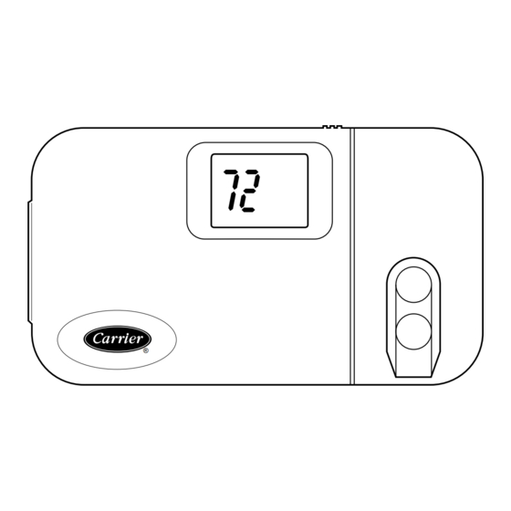
HEIGHT (IN.)
4-1/4
Fig. 1—Carrier Programmable Thermostat
• Close to or in a frequently used room, preferably on an inside
partitioning wall.
• On a section of wall without pipes or duct work.
Thermostat should NOT be mounted:
• Close to a window, on an outside wall, or next to a door leading
to the outside.
• Exposed to direct light and heat from a lamp, sun, fireplace, or
other temperature-radiating object which may cause a false
reading.
• Close to or in direct airflow from supply registers and return-air
grilles.
• In areas with poor air circulation, such as behind a door or in
an alcove.
Step 2—Set DIP Switches
There are 4 small switches on the back of the circuit board which
must be set by the installer. The ON position is indicated by small
letters on the switch itself. Ignore numbers 1-4 on the switch. The
switch designation (A through D) is on the circuit board next to the
switch. To change a switch position use the corner of a small
screwdriver to slide it between on and off. Make these selections
BEFORE installing the thermostat--it is much easier.
Switch A - Zoning Select (Active on all models)
This switch selects or defeats the 4 cycles per hour limit and a
5-minute compressor timeguard. These timers MUST be enabled
for normal operation and disabled for zoning applications. (In
zoning applications the zone control center performs these timing
functions.)
TO SET:
OFF— for normal operation. This is the factory default.
ON—for zoned installations ONLY.
Switch B - Setback Recovery (Active on all models)
Selects between normal and smart recovery from setback. Normal
recovery changes to the new setpoint at the programmed time.
Smart recovery, which is active in heating mode only, starts earlier
Form TSTAT-4SI
WIDTH (IN.)
DEPTH (IN.)
7-1/2
1-3/8
Pg 1
4-95
Replaces: TSTAT-1SI
A94134
Advertisement
Table of Contents

Subscribe to Our Youtube Channel
Related Manuals for Carrier Programmable Thermostats


Summary of Contents for Carrier Programmable Thermostats
-
Page 1: Programmable Thermostats
INTRODUCTION • Close to or in a frequently used room, preferably on an inside Carrier’s 7-day programmable thermostats are wall-mounted, low- partitioning wall. voltage thermostats which maintain room temperature by control- • On a section of wall without pipes or duct work. - Page 2 Table 1—Model Selection and Wiring Diagram Chart AIR CONDITIONER HEAT PUMP OUTDOOR UNIT 1 Speed 2 Speed 1 Speed 2 Speed 1-Stage Model AC Model 2S Requires Interface Control Model 2S Furnace See Fig. 2 See Fig. 8 or Dual Fuel Thermostat See Fig.
- Page 3 mode, FAN button must be pressed and held again. This adjustment controls only sensitivity and cycle rate—up to the maximum of 4 cycles per hour. While in Configuration Mode, these selections are available: TO ADJUST: Fahrenheit or Celsius—Selection 1. Enter configuration mode. Select between Fahrenheit or Celsius operation.
- Page 4 TWO-STAGE OR MODEL AC SINGLE-STAGE SINGLE-SPEED MODEL HP SINGLE-SPEED VARIABLE-SPEED THERMOSTAT FURNACE AIR CONDITIONER THERMOSTAT AIR CONDITIONER FURNACE 24 VAC HOT 24 VAC HOT HEAT STAGE 1 W/W1 HEAT STAGE 1 W/W1 W/W1 COOL STAGE 1 Y/Y2 COOL STAGE 1 Y/Y2 Y/Y2 O/W2...
- Page 5 MODEL HP TYPICAL SINGLE-SPEED MODEL 2S SINGLE-STAGE TWO-SPEED THERMOSTAT FURNACE AIR CONDITIONER THERMOSTAT FAN COIL AIR CONDITIONER COOL STAGE 1 Y1/W2 24 VAC HOT HEAT STAGE 1 W/W1 HEAT STAGE 1 W/W1 COOL STAGE 2 Y/Y2 COOL STAGE 1 Y/Y2 Y/Y2 O/W2 HEAT STAGE 2...
- Page 6 MODEL 2S TYPICAL TWO-SPEED MODEL 2S TWO-STAGE OR TWO-SPEED THERMOSTAT VARIABLE-SPEED HEAT PUMP THERMOSTAT FAN COIL AIR CONDITIONER FURNACE COOL/HEAT 24 VAC HOT Y1/W2 STAGE 1 RVS COOLING O/W2 W/W1 HEAT STAGE 1 W/W1 HEAT STAGE 3 W/W1 Y/Y2 * COOL/HEAT Y/Y2 COOL STAGE 2...
- Page 7 MODEL 2S SINGLE-SPEED THERMOSTAT FAN COIL HEAT PUMP 24 VAC HOT HEAT STAGE 2 W/W1 COOL/HEAT Y/Y2 Y/Y2 STAGE 1 RVS COOLING O/W2 HEAT STAGE 3 Y1/W2 24 VAC COMM. RVS HEATING TROUBLE See note 4 OUTDOOR SENSOR CONNECTION A94275 Fig.
- Page 8 AC) terminal. If present, thermostat is OK and problem is with equipment or wiring. If not present, replace thermo- stat. Copyright 1995 CARRIER Corp. • 7310 W. Morris St. • Indianapolis, IN 46231 tstat4si Manufacturer reserves the right to discontinue, or change at any time, specifications or designs without notice and without incurring obligations.
Need help?
Do you have a question about the Programmable Thermostats and is the answer not in the manual?
Questions and answers