Table of Contents
Advertisement
Quick Links
Advertisement
Table of Contents

Related Manuals for EnGenius EOC5510


Summary of Contents for EnGenius EOC5510
-
Page 1: User Manual
Wireless Long Range Access Point / Client Bridge EOC5510 User Manual V1.0... -
Page 2: Table Of Contents
................................. 6 ACKAGE ONTENTS 1.4 S ..............................6 YSTEM EQUIREMENT 1.5 H ..............................6 ARDWARE VERVIEW 2 EOC5510 MULTI-FUNCTION INSTRUCTION GUIDE ....................... 8 2.1 A ................................. 8 CCESS OINT 2.2 A WDS F ..........................8 CCESS OINT WITH UNCTION 2.3 C ................................ - Page 3 5.1 S -> IP S ..............................31 YSTEM ETTINGS 5.2 S -> S ..........................32 YSTEM PANNING ETTINGS 6 ROUTER SETTINGS ................................33 6.1 R -> WAN S ............................. 33 OUTER ETTINGS 6.1.1 WAN Settings -> Static IP ..........................33 6.1.2 WAN Settings ->...
-
Page 4: Product Overview
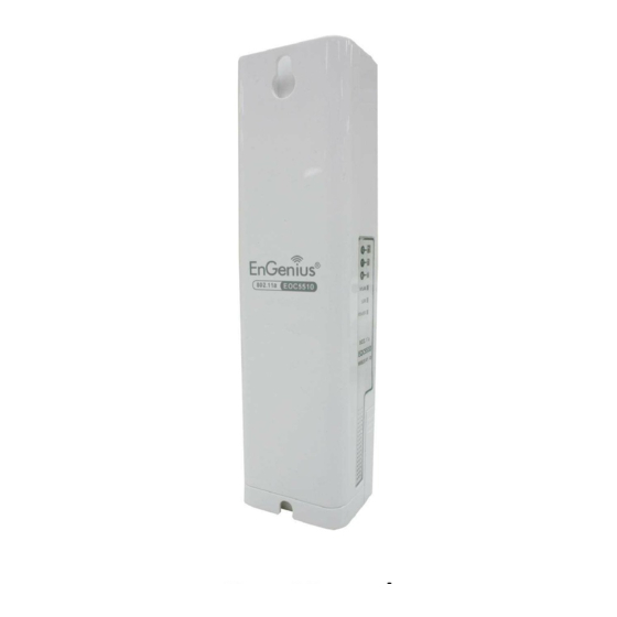
EOC5510 is easily to install almost anywhere with Power over Ethernet for quick outdoor installation. External N-type antenna provides better wireless signal quality and the antenna is upgradeable. EOC5510 uses 5G band of wireless signal to avoid interference of most digital signal such as mobile phone. - Page 5 Selection Support RSSI Indicator Users can select the best signal to connect with AP easily (CB mode) Flexible Access Point locations and cost savings. EOC5510 must uses Power-over-Ethernet the adapter provided in the package. Support Multi-SSID Allow clients to access different networks through a single access...
-
Page 6: Benefits
AP to access the internet. Multiple SSIDs EOC5510 supports up to 4 SSIDs on your access point. The following options can be set to each SS to each SSID: SSID for public or private network... -
Page 7: Package Contents
1* Ethernet Cable 1* QIG 1* CD (User Manual) 1* 5dBi 5GHz Dipole Antenna Auction: Using other Power Adapter than the one included with EOC5510 may cause damage of the device. 1.4 System Requirement The following conditions are the minimum system requirement. - Page 8 • Red: Bad Quality Power Requirements Active Ethernet (Power over Ethernet) Proprietary PoE design Power Adapter 24V / 0.6A DC...
-
Page 9: Eoc5510 Multi-Function Instruction Guide
2 EOC5510 Multi-Function Instruction Guide 2.1 Access Point In the Access Point Mode with WDS Function, EOC5510 function likes a central connection for any stations or clients that support IEEE 802.11a network. Stations and Client must configure the same SSID and Security Password to associate within the range. EOC5510 supports 4 different SSIDs to separate different clients at the same time. -
Page 10: Client Bridge
2.3 Client Bridge In the Client Bridge Mode, the EOC5510 function likes a wireless dongle. Connected to an Access Point wirelessly and surf internet whenever you want. Using Site Survey to scan all the Access Point within the range and configure its SSID and Security Password to associate with it. Connect you station to the LAN port of the EOC5510 via Ethernet. -
Page 11: Client Router
2.5 Client Router In the Client Router Mode, the EOC5510 has DHCP Server build inside that allows many LANs automatically generate an IP address to share the same Internet. Connect an AP/WISP Wirelessly and connect to LANs via wired. Client Router Mode is act completely opposite to the AP Router Mode. -
Page 12: Computer Settings
4. Click on the OK button to close this window, and then close LAN properties window. Auction: IP Address entered in the TCP/IP Properties needs to be at the same subnet of the EOC5510 IP Address. For example: EOC5510’s default IP Address is 192.168.1.1 so the IP Address in the TCP/IP... -
Page 13: Logging Method
1. Open web browser 2. Enter IP 192.168.1.1 into you address filter. Auction: If you have changed the EOC5510 LAN IP address, make sure you enter the correct IP Address. 3. After connected to the EOC5510 successfully, browser will pop out a Windows Security window. -
Page 14: Wireless Settings
4 Wireless Settings 4.1 Switching Operation Mode The EOC5510 supports 4 different operation modes: Access Point, Client Bridge, WDS Bridge, and Client Router. Click System Properties under System Section to begin. Device Name: Specify a name for the device, but it is not the broadcast SSID. It will be shown in SNMP management. -
Page 15: Wireless Settings
Mode and then enable WDS Link Settings function. 4.2 Wireless Settings 4.2.1 Access Point Mode -> Wireless Network Wireless Mode EOC5510 only supports 802.11a wireless band. Channel / Frequency The channel availability is based on the country’s regulation. Auto Place a Check to enable Auto channel selection. - Page 16 Auction: EOC5510 supports 5GHz wireless network. Only the wireless client which supports 5GHz network can associate with. Please make sure your wireless client supports 5GHz wireless network. SSID Specify the SSID for current profile. VLAN ID Specify the VLAN tag for current profile.
-
Page 17: Client Bridge Mode -> Wireless Network
4.2.2 Client Bridge Mode -> Wireless Network Wireless Mode EOC5510 only supports 802.11a wireless band. SSID Specify the SSID if known. SSID text box will be automatically fill in when select an AP in the Site Survey. Site Survey Using Site Survey to scan nearby APs and then select the AP to establish the connection. -
Page 18: Wds Bridge Mode -> Wireless Network
Auction: If the Access Point is suppressed its own SSID, SSID section will be blank, the SSID must be filled in manually. 4.2.3 WDS Bridge Mode -> Wireless Network Wireless Mode EOC5510 only supports 802.11a wireless band. Channel / Frequency The channel availability is based on the country’s regulation. Apply / Cancel... - Page 19 MAC Address Enter the Access Point’s MAC address that you would like to extend the wireless area into the MAC address filter. Mode Select Disable or Enable from the drop down list. Apply / Cancel Press Apply to apply the changes or Cancel to return previous settings. Auction: The Access Point that you would like to extend the wireless area must enter your Access Point’s MAC address.
-
Page 20: Client Router Mode -> Wireless Network
4.2.4 Client Router Mode -> Wireless Network Wireless Mode EOC5510 only supports 802.11a wireless band. SSID Specify the SSID if known. SSID text box will be automatically fill in when select an AP in the Site Survey. Site Survey Using Site Survey to scan nearby APs and then select the AP to establish the connection. -
Page 21: Wireless Security Settings
Auction: If the Access Point is suppressed its own SSID, SSID section will be blank, the SSID must be filled in manually. 4.3 Wireless Security Settings Wireless Security Settings section will guide you to the entire Security modes configuration: WEP, WPA-PSK, WPA2-PSK, WPA-PSK Mixed, WPA, WPA2, and WPA Mixed. -
Page 22: Wpa-Psk
4.3.2 WPA-PSK Security Mode Select WPA-PSK from the drop down list to begin the configuration. Encryption Select Auto, TKIP or AES for Encryption type. Passphrase Specify the security password. Group Key Update Specify Group Key Update Interval time. Interval Group Key Update Specify Group Key Update Timeout time. -
Page 23: Wpa-Psk Mixed
Encryption Select Auto, TKIP or AES for Encryption type. Passphrase Specify the security password. Group Key Update Specify Group Key Update Interval time. Interval Group Key Update Specify Group Key Update Timeout time. Timeout Pairwise Key Update Specify Pairwise Key Update Timeout time. Interval 4.3.4 WPA-PSK Mixed Security Mode... -
Page 24: Wpa
4.3.5 WPA WPA security mode is for 802.1x authentication. You must provide a RADIUS Server to check the permission of access the network. Security Mode Select WPA from the drop down list to begin the configuration. Encryption Select Auto, TKIP or AES for Encryption type. Radius Server Specify Radius Server IP Address. -
Page 25: Wpa2
4.3.6 WPA2 WPA2 security mode is for 802.1x authentication. You must provide a RADIUS Server to check the permission of access the network. Security Mode Select WPA2 from the drop down list to begin the configuration. Encryption Select Auto, TKIP or AES for Encryption type. Radius Server Specify Radius Server IP Address. -
Page 26: Wpa Mixed
4.3.7 WPA Mixed WPA Mixed security mode is for 802.1x authentication. You must provide a RADIUS Server to check the permission of access the network. Security Mode Select WPA Mixed from the drop down list to begin the configuration. Encryption Select Auto, TKIP or AES for Encryption type. -
Page 27: Radius Accounting
4.3.8 Radius Accounting Radius Accounting function allows you to record the statics of user login. Your Radius Server must have the ability to support Radius Accounting function. Radius Accounting Select Enable to begin configuration of Radius Accounting. Radius Accounting Server Specify Radius Accounting Server IP. -
Page 28: Wireless -> Wireless Advanced Settings
4.4 Wireless -> Wireless Advanced Settings Data Rate Select Data Rate from the drop down list. Data rate will affect the efficiency of the throughput. If the data rate is set to a small number, the lower through will get but it can transmit to longer distance. - Page 29 Channel Bandwidth Select Channel Bandwidth from the drop down list. Decrease channel bandwidth may cause lower throughput but less collision. Distance Specify distance rage between AP and Clients. Longer distance may lose high connection speed. Wireless Traffic Shaping Place a Check to enable Wireless Traffic Shaping function. Incoming Traffic Limit Specify the wireless transmission speed for downloading.
-
Page 30: Wireless -> Wireless Mac Filter
Wireless MAC Filters is used to Allow or Deny wireless clients, by their MAC addresses, accessing the Network. You can manually add a MAC address to restrict the permission to access EOC5510. The default setting is Disable Wireless MAC Filters. -
Page 31: Wireless -> Wds Link Settings
4.6 Wireless -> WDS Link Settings WDS Link Settings is used to establish a connection between Access Points but the device is not losing Access Point function. AP has WDS function can extend the wireless coverage and allow LANs to communicate each other. MAC Address Enter the Access Point’s MAC address that you would like to extend the wireless area. -
Page 32: Lan Settings
5.1 System -> IP Settings This section is only available for Non-Router Mode. IP Settings allows you to LAN port IP address of the EOC5510. Auction: Changing LAN IP Address will change LAN Interface IP address. Webpage will automatically redirect to the new IP address after Apply. -
Page 33: System -> Spanning Tree Settings
5.2 System -> Spanning Tree Settings Spanning Tree Status Select the Radio button to On or Off Spanning Tree function. Bridge Hello Time Specify Bridge Hello Time in second. Bridge Max Age Specify Bridge Max Age in second. Bridge Forward Delay Specify Bridge Forward Delay in second. -
Page 34: Router Settings
6 Router Settings This section is only available at Client Router Mode. 6.1 Router -> WAN Settings There are four different types of WAN connection: Static IP, DHCP, PPPoE and PPTP. Please contact your ISP to select the connection type. 6.1.1 WAN Settings ->... - Page 35 Internet Connection Type Select Static IP to begin configuration of the Static IP connection. Account Name Specify Account Name that is provided by ISP. Domain Name Specify Domain Name that is provided by ISP. Specify the Maximum Transmit Unit size. Suggest remain in Auto. IP Address Specify WAN port IP address.
- Page 36 MTU is set too low, the router will fragment packets unnecessarily and in extreme cases may be unable to establish some connections. In either case, network performance can suffer.
-
Page 37: Wan Settings -> Dhcp (Dynamic Ip)
6.1.2 WAN Settings -> DHCP (Dynamic IP) Select DHCP as your WAN connection type to obtain your IP address automatically. You will need to enter Account Name as your hostname and DNS (Optional). Internet Connection Type Select DHCP to begin configuration of the DHCP connection. Account Name Specify Account Name that is provided by ISP. - Page 38 Apply / Cancel Press Apply to apply the changes or Cancel to return previous settings. Auction: If the router's MTU is set too high, packets will be fragmented downstream. If the router's MTU is set too low, the router will fragment packets unnecessarily and in extreme cases may be unable to establish some connections.
-
Page 39: Wan Settings -> Pppoe (Point-To-Point Protocol Over Ethernet)
Select PPPoE as your WAN connection type if your ISP provides Username and Password. PPPoE is a DSL service and please remove your PPPoE software from your computer, the software is not worked in EOC5510. Internet Connection Type Select PPPoE to begin configuration of the PPPoE connection. - Page 40 Connect on Demand Select the Radio button to specify the maximum idle time. Internet connection will disconnect when it reach the maximum idle time, but it will automatically connect when user tries to access the network. Keep Alive Select the Radio button to keep internet connection always on. Specify the redial period once the internet lose connection.
-
Page 41: Wan Settings -> Pptp (Point-To-Point Tunneling Protocol)
6.1.4 WAN Settings -> PPTP (Point-to-Point Tunneling Protocol) Select PPTP as your WAN connection type if your ISP provides information about IP Address, Subnet Mask, Default Gateway (Optional), DNS (Optional), Server IP, Username, and Password. Internet Connection Type Select PPTP to begin configuration of the PPTP connection. - Page 42 Specify the Maximum Transmit Unit size. Suggest remain in Auto. IP Address Specify WAN port IP address. IP Subnet Mask Specify WAN IP Subnet Mask. Gateway IP Address Specify WAN Gateway IP address. PPTP Server Specify PPTP Server IP address. Username Specify the Username that is given by your ISP.
-
Page 43: Router -> Lan Settings
6.2 Router -> LAN Settings IP Address Specify LAN port IP address. IP Subnet Mask Specify LAN IP Subnet Mask. WINS Server IP Specify WINS Server IP. Use Router As DHCP Place a Check to enable DHCP server. Server Starting IP Address Specify DHCP server starting IP address. -
Page 44: Router -> Vpn Pass Through
6.3 Router -> VPN Pass Through VPN Pass Through is used to allow certain protocol to be tunneled through an IP network such as PPTP and L2TP or implement secure exchange of packets at the IP Layer such as IPSec. PPTP Pass Through Place a Check to enable PPTP protocol passes through WAN. -
Page 45: Router -> Port Forwarding
6.4 Router -> Port Forwarding Port Forwarding is used to allow a public service such as Web Server, Mail Server, and FTP server to be set up. For example: Set up a Web Server on your computer with port number 8080. Visitor on the internet can access your Web Server by entering WAN Port IP with port number 8080. -
Page 46: Information Status
IP Address Specify IP address. Save / Cancel Press Save to apply the changes or Cancel to return previous settings. 7 Information Status Status section is on the navigation drop-down menu. You will then see three options: Main, Wireless Client List, System Log, WDS Link Status, Connection Status, and DHCP Client Table. Each option is described in detail below. -
Page 47: Status -> Wireless Client List
Click on the Wireless Client List link under the Status drop-down menu. This page displays the list of Clients that are associated to the EOC5510. The MAC addresses and signal strength for each client is displayed. Click on the Refresh button to... -
Page 48: Status -> System Log
7.3 Status -> System Log Click on the System Log link under the Status drop-down menu. The device automatically logs (records) events of possible interest in its internal memory. If there is not enough internal memory for all events, logs of older events are deleted, but logs of the latest events are retained. -
Page 49: Status -> Wds Link Status
7.4 Status -> WDS Link Status The WDS Link Status will only show in WDS Bridge Mode. Click on the WDS Link Status link under the Status drop-down menu. This page displays the current status of WDS link, including station ID, MAC address, status and RSSI. -
Page 50: Status -> Dhcp Client Table
Click on the DHCP Client List link under the Status drop-down menu. This page displays the list of Clients that are associated to the EOC5510 through DHCP. The MAC addresses and signal strength for each client is displayed. Click on the Refresh button to... -
Page 51: Management Settings
8 Management Settings Management section is on the navigation drop-down menu. You will then see seven options: administration, management VLAN, SNMP settings, backup/restore settings, firmware upgrade, time settings, and log. Each option is described below. 8.1 Management -> Administration Click on the Administration link under the Management menu. This option allows you to create a user name and password for the device. -
Page 52: Management -> Management Vlan
Name Specify Username for login. Password Specify a Password for login Confirm Password Re-enter the Password for confirmation. Remote Management Select the Radio button to Enable or Disable Remote Management. Remote Upgrade Select the Radio button to Enable or Disable Remote Upgrade. Remote Management Specify the Port number for Remote Management. -
Page 53: Management -> Snmp Settings
Press Apply to apply the changes or Cancel to return previous settings. Auction: If you reconfigure the Management VLAN ID, you may lose connection to the EOC5510. Verify DHCP server can support the reconfigured VLAN ID, and then re-connect to the new IP address. -
Page 54: Management -> Backup/Restore Settings
SNMP Enable/Disable Select the Radio button to Enable or Disable SNMP function. Contact Specify the contact details of the device. Location Specify the location of the device. Community Name Specify the password for access the SNMP community for read only access. Community Name Specify the password for access the SNMP community for read and write access. -
Page 55: Management -> Firmware Upgrade
Save A Copy of Current Click on Backup to save current configured settings. Settings Restore Saved Settings EOC5510 can restore a previous setting that has been saved. Click on Browse to from a File select the file and Restore. Revert to Factory Default Click on Factory Default button to reset all the settings to the default values. -
Page 56: Management -> Log
Manually Set Date and Manually setup the date and time. Time Automatically Get Date Specify the Time Zone from the drop down list and Place a Check to specify the IP and Time address of the NTP Server manually or uses default NTP Server. Apply / Cancel Press Apply to apply the changes or Cancel to return previous settings. -
Page 57: Management -> Diagnostics
triggered on the Ethernet and Wireless interface. This log can be referred when an unknown error occurs on the system or when a report needs to be sent to the technical support department for debugging purposes. Syslog Select Enable or Disable Syslog function from the drop down list. Log Server IP Address Specify the Log Server IP address. - Page 58 connection quality and trace the routing table to the target. Target IP Specify the IP address you would like to search. Ping Packet Size Specify the packet size of each ping. Number of Pings Specify how many times of ping. Start Ping Press Start Ping to begin.
-
Page 59: Network Configuration Example
9 Network Configuration Example This chapter describes the role of the EOC5510 with 4 different modes. The Access Point mode’s default configuration is a central unit of the wireless network or as a root device of the wired environment. 9.1 Access Point... -
Page 60: Client Bridge Mode
Configure VLAN ID in your wireless device if available. Step4 Select correct authentication type and password. Auction: EOC5510’s Access Point Mode does not provide DHCP server so the Wireless Client IP address must configure manually at the same subnet in Local Area Network. 9.2 Client Bridge Mode Client Bridge Mode functions like a wireless dongle. -
Page 61: Client Router
Auction: Each WDS bridge’s device must use the same Subnet, Wireless Mode, Wireless Channel, and Security Setting. 9.4 Client Router In the Client Router Mode, the EOC5510 has DHCP Server build inside that allows many LANs automatically generate an IP address to share the same Internet. Connect an AP/WISP Wirelessly and... - Page 62 Please refer to the last section to check Access point’s configuration. Client Router Step1 Login to the web-based configuration interface with default IP 192.168.1.1 Step2 Select your country or region’s regulation. Step3 Select Operation Mode to Client Router from System Properties. Step4 Change your Local Area Network setting to Obtain an IP Address Automatically.
-
Page 63: Appendix A - Fcc Interference Statement
Appendix A – FCC Interference Statement Federal Communication Commission Interference Statement This equipment has been tested and found to comply with the limits for a Class B digital device, pursuant to Part 15 of the FCC Rules. These limits are designed to provide reasonable protection against harmful interference in a residential installation.
Need help?
Do you have a question about the EOC5510 and is the answer not in the manual?
Questions and answers