Table of Contents
Advertisement
Available languages
Available languages
Advertisement
Table of Contents

Related Manuals for MSI Z97-G45 GAMING


Summary of Contents for MSI Z97-G45 GAMING
- Page 1 Preface Z97-G45 GAMING Motherboard G52-78211X8...
-
Page 2: Copyright Notice
ASMedia Technology Inc. ® ■ iPad, iPhone, and iPod are trademarks of Apple Inc. ■ Qualcomm Atheros and Killer are trademarks of Qualcomm Atheros Inc. Revision History Revision Revision History Date V1.1 Release for Z97-G45 GAMING 2014/ 04 Preface... -
Page 3: Technical Support
If a problem arises with your system and no solution can be obtained from the user’s manual, please contact your place of purchase or local distributor. Alternatively, please try the following help resources for further guidance. Visit the MSI website for technical guide, BIOS updates, driver updates, and other information: http://www.msi.com/service/download/ Contact our technical staff at: http://register.msi.com/... -
Page 4: Safety Instructions
Safety Instructions ■ Always read the safety instructions carefully. ■ Keep this User’s Manual for future reference. ■ Keep this equipment away from humidity. ■ Lay this equipment on a reliable flat surface before setting it up. ■ The openings on the enclosure are for air convection hence protects the equipment from overheating. - Page 5 FCC-B Radio Frequency Interference Statement This equipment has been tested and found to comply with the limits for a Class B digital device, pursuant to Part 15 of the FCC Rules. These limits are designed to provide reasonable protection against harmful interference in a residential installation. This equipment generates, uses and can radiate radio frequency energy and, if not installed and used in accordance with the instructions, may cause harmful interference to radio communications.
- Page 6 Radiation Exposure Statement This equipment complies with FCC radiation exposure limits set forth for an uncontrolled environment. This equipment and its antenna should be installed and operated with minimum distance 20 cm between the radiator and your body. This equipment and its antenna must not be co-located or operating in conjunction with any other antenna or transmitter.
-
Page 7: Battery Information
Replace only with the same or equivalent type recommended by the manufacturer. Chemical Substances Information In compliance with chemical substances regulations, such as the EU REACH Regulation (Regulation EC No. 1907/2006 of the European Parliament and the Council), MSI provides the information of chemical substances in products at: http://www.msi.com/html/popup/csr/evmtprtt_pcm.html Preface... - Page 8 MSI will comply with the product take back requirements at the end of life of MSI-branded products that are sold into the EU. You can return these products to local collection points.
- Page 9 MSI će poštovati zahtev o preuzimanju ovakvih proizvoda kojima je istekao vek trajanja, koji imaju MSI oznaku i koji su prodati u EU. Ove proizvode možete vratiti na lokalnim mestima za prikupljanje.
- Page 10 MSI si adeguerà a tale Direttiva ritirando tutti i prodotti marchiati MSI che sono stati venduti all’interno dell’Unione Europea alla fine del loro ciclo di vita.
-
Page 11: Table Of Contents
CONTENTS ▍ English ...................... En-1 Motherboard Specifications ................En-2 Connectors Quick Guide ..................En-5 Back Panel Quick Guide ..................En-7 CPU (Central Processing Unit) ................En-9 Memory ......................En-13 Mounting Screw Holes ..................En-14 Power Supply ....................En-15 Expansion Slots ....................En-16 Video/ Graphics Cards ..................En-17 Internal Connectors ..................En-18 Voltage Checkpoints ..................En-25 Jumper ......................En-26 Drivers and Utilities ..................En-27... - Page 12 Emplacements d’extension ................Fr-16 Cartes Vidéo/ Graphics ..................Fr-17 Connecteurs internes ..................Fr-18 Point de vérification tension ................Fr-25 Cavaliers ......................Fr-26 Pilotes et Utilitaires ....................Fr-27 Configuration BIOS ...................Fr-28 Opération ......................Fr-31 Русский ....................Ru-1 Характеристики материнской платы .............. Ru-2 Краткое руководство по разъемам ..............Ru-5 Краткое...
-
Page 13: English
English Thank you for choosing the Z97-G45 GAMING Series (MS-7821 v1.X) ATX motherboard. The Z97-G45 GAMING Series motherboards are based on Intel Z97 chipset for optimal system efficiency. Designed to fit the advanced ® Intel LGA1150 processor, the Z97-G45 GAMING Series motherboards ®... -
Page 14: Motherboard Specifications
Motherboard Specifications ■ Supports 4th and 5th Generation Intel Core™ Processors, and ® Intel Pentium and Celeron Processors for Socket LGA1150 Support ® ® ® Chipset ■ Intel Z97 Express Chipset ® Memory ■ 4x DDR3 memory slots supporting up to 32GB ■... - Page 15 Back Panel ■ 1x PS/2 keyboard/ mouse combo port ■ 2x USB 2.0 ports Connectors ■ 1x Clear CMOS button ■ 1x Coaxial S/PDIF OUT connector ■ 1x Optical S/PDIF OUT connector ■ 1x VGA port ■ 1x DVI-D port ■...
- Page 16 Norton Internet Security Solution Form ■ ATX Form Factor ■ 12.0 in. x 9.6 in. (30.5 cm x 24.4 cm) Factor For the latest information about CPU, please visit http://www.msi.com/cpu-support/ For more information on compatible components, please visit http://www.msi.com/test-report/ En-4...
-
Page 17: Connectors Quick Guide
Connectors Quick Guide MSATA_1 DIMM1 CPU Socket DIMM2 SYSFAN1 DIMM3 DIMM4 JPWR2 CPUFAN1 CPUFAN2 Back Panel JPWR1 SYSFAN3 PCI_E1 PCI_E2 JUSB4 PCI_E3 SATA5_6 PCI_E4 SATA3_4 PCI_E5 SATA1_2 JCI1 PCI_E6 JBAT1 PCI_E7 JUSB3 JUSB2 JAUD1 JUSB1 JCOM1 JFP1 SYSFAN2 JFP2 JTPM1 En-5... - Page 18 Connectors Reference Guide Port Name Port Type Page Back Panel I/O ports En-7 CPU Socket LGA1150 CPU Socket En-9 CPUFAN1~2,SYSFAN1~3 Fan Power Connectors En-19 DIMM1~4 DDR3 Memory Slots En-13 JAUD1 Front Panel Audio Connector En-23 JBAT1 Clear CMOS Jumper En-26 JCI1 Chassis Intrusion Connector En-22...
-
Page 19: Back Panel Quick Guide
Back Panel Quick Guide PS/2 Keyboard/ Mouse Combo Coaxial LAN Port Port * S/PDIF-Out USB 3.0 Port Line-In RS-Out Line-Out CS-Out Optical SS-Out USB 3.0 Port HDMI USB 2.0 Port * DVI-D Port S/PDIF-Out Clear CMOS Button * Gaming Device Port. ▶... - Page 20 VGA+DVI-D DVI-D+HDMI HDMI+VGA HDMI+VGA+DVI-D Extend mode ◯ ◯ ◯ ◯ (Extend the desktop to the other monitors) Clone mode ◯ ◯ ◯ ◯ (Monitors have the same screen) ▶ USB 2.0 Port The USB 2.0 port is for attaching USB 2.0 devices such as keyboard, mouse, or other USB 2.0-compatible devices.
-
Page 21: Cpu (Central Processing Unit
This motherboard is designed to support overclocking. Before attempting to overclock, please make sure that all other system components can tolerate overclocking. Any attempt to operate beyond product specifications is not recommend. MSI does not guarantee the damages or risks caused by inadequate operation beyond product specifications. - Page 22 CPU & Heatsink Installation When installing a CPU, always remember to install a CPU heatsink. A CPU heatsink is necessary to prevent overheating and maintain system stability. Follow the steps below to ensure correct CPU and heatsink installation. Wrong installation can damage both the CPU and the motherboard.
- Page 23 3. Align the notches with the socket alignment keys. Lower the CPU straight down, without tilting or sliding the CPU in the socket. Inspect the CPU to check if it is properly seated in the socket. 4. Close and slide the load plate under the retention knob. Close and engage the load lever.
- Page 24 7. Locate the CPU fan connector on the motherboard. 8. Place the heatsink on the motherboard with the fan’s cable facing towards the fan connector and the fasteners matching the holes on the motherboard. CPU fan connector 9. Push down the heatsink until the four fasteners get wedged into the holes on the motherboard.
-
Page 25: Memory
Memory These DIMM slots are used for installing memory modules. DIMM1 DIMM2 DIMM3 DIMM4 Video Demonstration Watch the video to learn how to install memories at the address below. http://youtu.be/76yLtJaKlCQ Dual-Channel mode Population Rule In Dual-Channel mode, the memory modules can transmit and receive data with two data bus channels simultaneously. -
Page 26: Mounting Screw Holes
Mounting Screw Holes When installing the motherboard, first install the necessary mounting stands required for an motherboard on the mounting plate in your computer case. If there is an I/O back plate that came with the computer case, please replace it with the I/O backplate that came with the motherboard package. -
Page 27: Power Supply
Power Supply Video Demonstration Watch the video to learn how to install power supply connectors. http://youtu.be/gkDYyR_83I4 JPWR1~2: ATX Power Connectors These connectors allow you to connect an ATX power supply. To connect the ATX power supply, align the power supply cable with the connector and firmly press the cable into the connector. -
Page 28: Expansion Slots
Expansion Slots This motherboard contains numerous slots for expansion cards, such as discrete graphics or audio cards. PCI_E1~E7: PCIe Expansion Slot The PCIe slot supports the PCIe interface expansion card. PCIe 3.0 x16 Slot PCIe 2.0 x1 Slot Important When adding or removing expansion cards, always turn off the power supply and unplug the power supply power cable from the power outlet. -
Page 29: Video/ Graphics Cards
Adding on one or more discrete video cards will significantly boost the system’s graphics performance. For best compatibility, MSI graphics cards are recommended. Video Demonstration Watch the video to learn how to install a graphics card on PCIe x16 slot with butterfly lock. -
Page 30: Internal Connectors
Internal Connectors SATA1~6: SATA Connector This connector is a high-speed SATA interface port. Each connector can connect to one SATA device. SATA devices include disk drives (HDD), solid state drives (SSD), and optical drives (CD/ DVD/ Blu-Ray). Video Demonstration Watch the video to learn how to Install SATA HDD. http://youtu.be/RZsMpqxythc SATA6 SATA5... - Page 31 CPUFAN1~2,SYSFAN1~3: Fan Power Connectors The fan power connectors support system cooling fans with +12V. If the motherboard has a System Hardware Monitor chipset on-board, you must use a specially designed fan with a speed sensor to take advantage of the CPU fan control. Remember to connect all system fans.
-
Page 32: Jfp1, Jfp2: System Panel Connectors
JFP1, JFP2: System Panel Connectors These connectors connect to the front panel switches and LEDs. The JFP1 connector is compliant with the Intel Front Panel I/O Connectivity Design Guide. When ® installing the front panel connectors, please use the optional M-Connector to simplify installation. -
Page 33: Usb 3.0 Expansion Connector
JUSB1~3: USB 2.0 Expansion Connector This connector is designed for connecting high-speed USB peripherals such as USB HDDs, digital cameras, MP3 players, printers, modems, and many others. Important Note that the VCC and GND pins must be connected correctly to avoid possible damage. - Page 34 JTPM1: TPM Module Connector This connector connects to a optional TPM (Trusted Platform Module) Module. Please refer to the TPM security platform manual for more details and usages. JCI1: Chassis Intrusion Connector This connector connects to the chassis intrusion switch cable. If the computer case is opened, the chassis intrusion mechanism will be activated.
- Page 35 JAUD1: Front Panel Audio Connector This connector allows you to connect the front audio panel located on your computer case. This connector is compliant with the Intel Front Panel I/O Connectivity Design ® Guide. MSATA_1: mSATA Slot The mSATA slot is for mSATA interface solid state drives (SSD) Important The SATA6 port will be unavailable when install a SSD in the mSATA port.
- Page 36 JCOM1: Serial Port Connector This connector is a 16550A high speed communication port that sends/receives 16 bytes FIFOs. You can attach a serial device. En-24...
-
Page 37: Voltage Checkpoints
Voltage Checkpoints These voltage checkpoints are used to measure the current system voltages. A multimeter (not included) will be required to check voltages. V-Check Spots These voltage check spots are for you to measure CPU and PCH voltages. To check the voltage, please attach the positive lead of the multimeter to these spots and the negative lead to any ground spot. -
Page 38: Jumper
Jumper JBAT1: Clear CMOS Jumper There is CMOS RAM onboard that is external powered from a battery located on the motherboard to save system configuration data. With the CMOS RAM, the system can automatically boot into the operating system (OS) every time it is turned on. If you want to clear the system configuration, set the jumpers to clear the CMOS RAM. -
Page 39: Drivers And Utilities
After you install the operating system you will need to install drivers to maximize the performance of the new computer you just built. MSI motherboard comes with a Driver Disc. Drivers allow the computer to utilize your motherboard more efficiently and take advantage of any special features we provide. -
Page 40: Bios Setup
"MSI Fast Boot" utility screen. Important • Please be sure to install the “MSI Fast Boot” utility before using it to enter the BIOS setup. • The items under each BIOS category described in this chapter are under continuous update for better system performance. Therefore, the description may be slightly different from the latest BIOS and should be held for reference only. - Page 41 Overview After entering BIOS, the following screen is displayed. Temperature monitor My Favorites Language System information Boot device priority bar Virtual OC Genie Button BIOS menu BIOS menu selection selection Menu display ▶ BIOS menu selection The following options are available: ■...
- Page 42 Enables or disables the OC Genie function by clicking on this button. When enabled, this button will be light. Enabling OC Genie function can automatically overclock with MSI optimized overclocking profile. Important We recommend that you do not to make any modification in OC menu mode and do not to load defaults after enabling the OC Genie function.
-
Page 43: Operation
Operation You can control BIOS settings with the mouse and the keyboard. The following table lists and describes the hot keys and the mouse operations. Hot key Mouse Description <↑↓→← > Select Item Move the cursor <Enter> Select Icon/ Field Click/ Double-click the left button... - Page 44 OC Menu This menu is for advanced users who want to overclock the mainboard. Important • Overclocking your PC manually is only recommended for advanced users. • Overclocking is not guaranteed, and if done improperly, can void your warranty or severely damage your hardware.
- Page 45 < CPU BCLK Setting > ▶ CPU Base Clock (MHz) [Default] Sets the CPU Base clock. You may overclock the CPU by adjusting this value. Please note that overclocking behavior and stability is not guaranteed. This item appears when the installed processor supports this function. <...
- Page 46 ▶ VR 12VIN OCP Expander [Auto] Expands the limitation of VR Over Current Protection with 12V input voltage. The higher expanding value indicates less protection. Therefore, please adjust the current carefully if needed, or it may damage the CPU/ VR MOS. If set to "Auto", BIOS will configure this setting automatically.
- Page 47 ▶ CPU VRM Over Temperature Shutdown [Enabled] Sets the system whether be powered off or not when the CPU VRM temperature over the limitation temperature of CPU VRM protection. [Enabled] The system will be off when over the specified temperature. [Disabled] Disables this function.
- Page 48 ▶ CPU Technology Support Press <Enter> to enter the sub-menu. The sub-menu shows what the key features does the installed CPU support. Read only. ▶ MEMORY-Z Press <Enter> to enter the sub-menu. This sub-menu displays all the settings and tim- ings of installed memory.
- Page 49 ▶ Adjacent Cache Line Prefetch [Enabled] Enables or disables the CPU hardware prefetcher (MLC Spatial prefetcher). [Enabled] Enables adjacent cache line prefetching for reducing the cache latency time and tuning the performance to the specific application. [Disabled] Enables the requested cache line only. ▶...
- Page 50 ▶ EIST [Enabled] Enables or disables the Enhanced Intel SpeedStep Technology. This item will ap- ® pear when "Simple/ Advanced Mode" is set to [Simple]. [Enabled] Enables the EIST to adjust CPU voltage and core frequency dynami- cally. It can decrease average power consumption and average heat production.
-
Page 51: Deutsch
Diese Z97-G45 GAMING Motherboard basiert auf dem Intel Z97 Chipsatz und ermöglicht so ein optimales und effizientes ® System. Entworfen, um den hochentwickelten Intel LGA1150 Prozessor ® zu unterstützen, stellt die Z97-G45 GAMING die ideale Lösung zum Aufbau eines professionellen Hochleistungsdesktopsystems dar. -
Page 52: Spezifikationen
Spezifikationen Prozessor ■ Die Intel Core™ Prozessoren der 4. und 5. Generation und ® Intel Pentium und Celeron Prozessoren für LGA 1150 Sockel ® ® ® Chipsatz ■ Intel Z97 Express Chipsatz ® Speicher ■ 4x DDR3 Speicherplätze unterstützen bis zu 32GB ■... - Page 53 Hintere Ein-/ ■ PS/2 Tastatur-/Maus-Combo-Anschluss x1 ■ USB 2.0 Anschlüsse x2 und Ausgänge ■ Clear CMOS Taste x1 ■ koaxialer S/PDIF-Ausgang x1 ■ optischer S/PDIF-Ausgang x1 ■ VGA Anschluss x1 ■ DVI-D Anschluss x1 ■ HDMI Anschluss x1 ■ LAN (RJ45) Anschluss x1 ■...
- Page 54 ■ Norton Internet Security Solution Form Faktor ■ ATX Form Faktor ■ 12,0 Zoll x 9,6 Zoll (30,5 cm x 24,4 cm) Weitere CPU Informationen finden Sie unter http://www.msi.com/cpu-support/ Die neusten Informationen über kompatible Bauteile finden Sie unter http://www.msi.com/test-report/ De-4...
-
Page 55: Anschlussübersicht
Anschlussübersicht MSATA_1 DIMM1 CPU Sockel DIMM2 SYSFAN1 DIMM3 DIMM4 JPWR2 CPUFAN1 CPUFAN2 Rück- tafel JPWR1 SYSFAN3 PCI_E1 PCI_E2 JUSB4 PCI_E3 SATA5_6 PCI_E4 SATA3_4 PCI_E5 SATA1_2 JCI1 PCI_E6 JBAT1 PCI_E7 JUSB3 JUSB2 JAUD1 JUSB1 JCOM1 JFP1 SYSFAN2 JFP2 JTPM1 De-5... - Page 56 Übersicht der Motherboard-Anschlüsse Port-Name Port-Typ Seite Rücktafel E/A Anschlüsse De-7 CPU Sockel LGA1150 CPU Sockel De-9 CPUFAN1~2,SYSFAN1~3 Stromanschlüsse für Lüfter De-19 DIMM1~4 DDR3 Speichersteckplätze De-13 JAUD1 Audioanschluss des Frontpanels De-23 JBAT1 Steckbrücke zur CMOS-Löschung De-26 JCI1 Gehäusekontaktanschluss De-22 JCOM1 Serieller Anschluss De-24 JFP1, JFP2 Systemtafelanschlüsse...
-
Page 57: Rücktafel-Übersicht
Rücktafel-Übersicht PS/2 Tastatur/ koaxialer Maus Combo S/PDIF- USB 3.0 Anschluss * Anschluss Ausgang Anschluss Line-In RS-Out Line-Out CS-Out Optischer SS-Out USB 3.0 HDMI USB 2.0 DVI-D Anschluss S/PDIF-Ausgang Anschluss Anschluss * Clear CMOS Taste * Spiele-Gerät-Port. ▶ PS/2 Tastatur/Maus Combo Anschluss Die Standard PS/2 Maus/Tastatur Stecker DIN ist für eine PS/2 Maus/Tastatur. - Page 58 VGA+DVI-D DVI-D+HDMI HDMI+VGA HDMI+VGA+DVI-D Erweiterter-Modus (Erweiterung des ◯ ◯ ◯ ◯ Desktops auf den anderen Monitor) Clone-Modus ◯ ◯ ◯ ◯ (Monitore zeigen das gleiche Bild) ▶ USB 2.0 Anschluss Der USB 2.0 Anschluss dient zum direkten Anschluss von USB 2.0-Geräten, wie etwa Tastatur, Maus oder weiterer USB 2.0-kompatibler Geräte.
-
Page 59: Cpu (Prozessor
CPU (Prozessor) Erklärung zur LGA 1150 CPU Die Obserseite der LGA 1150 CPU hat zwei Justierungen und ein gelbes Dreieck um die korrekte Ausrichtung der CPU auf dem Motherboard zu gewährleisten. Das gelbe Dreieck des Prozessors definiert die Position des ersten Pins. Kerbe Kerbe Das goldene Dreieck des Prozessors... - Page 60 CPU & Kühlkörper Einbau Wenn Sie die CPU einbauen, denken sie bitte daran einen CPU-Kühler zu installieren. Ein CPU-Kühlkörper ist notwendig, um eine Überhitzung zu vermeiden und die Systemstabilität beizubehalten. Befolgen Sie die nachstehenden Schritte, um die richtige CPU und CPU-Kühlkörper Installation zu gewährleisten. Ein fehlerhafter Einbau führt zu Schäden an der CPU und dem Motherboard.
- Page 61 3. Positionieren Sie die Kerben mit die Justiermarkierungen des Sockels. Setzen Sie die CPU nach unten, ohne Kippen oder Schieben der CPU im Sockel. Begutachten Sie, ob die CPU richtig im Sockel sitzt. 4. Schließen Sie und schieben Sie die Abdeckplatte unter dem Rückhalteknopf. Verschließen Sie den Verschlusshebel.
- Page 62 7. Machen Sie den CPU-Lüfteranschluss auf dem Motherboard ausfinding. 8. Setzen Sie den Kühlkörper auf die CPU und beachten Sie die Übereinstimmung der Lüfterverankerungen mit den dafür vorgsehenen Löchern auf der Motherboard -Platine. CPU-Lüfteranschluss 9. Drücken Sie nach der korrekten Positionierung des Kühlkörpers die Arretierungsstifte mit leichtem Druck nach unten bis sie einrasten.
-
Page 63: Speicher
Speicher Die DIMM-Steckplätze nehmen Arbeitsspeichermodule auf. Die neusten Informationen über kompatible Bauteile finden Sie unter http://www.msi.com/service/test-report/ DIMM1 DIMM2 DIMM3 DIMM4 Video-Demonstration Anhand dieses Video an untenstehender Adresse erfahren Sie, wie Sie die Speichermodule installieren. http://youtu.be/76yLtJaKlCQ Populationsregeln für Dual-Kanal-Speicher Im Dual-Kanal-Modus können Arbeitsspeichermodule Daten über zwei Datenbusleitungen gleichzeitig senden und empfangen. -
Page 64: Schraubenlöcher Für Die Montage
Schraubenlöcher für die Montage Verwenden Sie die dem Motherboard beiliegende I/O-Platte und setzen Sie sie mit leichtem Druck von innen in die Aussparung des Computergehäuses ein. Zur Installation des Motherboards in Ihrem PC-Gehäuse befestigen Sie zunächst die dem Gehäuse beiliegenden Abstandhalter im Gehäuse. Legen Sie das Motherboard mit den Schraubenöffnungen über den Abstandhaltern und schrauben Sie das Motherboard mit den dem Gehäuse beiliegenden Schrauben fest. -
Page 65: Stromversorgung
Stromversorgung Video-Demonstration Anhand dieses Video an untenstehender Adresse erfahren Sie, wie Sie die Stromversorgungsstecker installieren. http://youtu.be/gkDYyR_83I4 JPWR1~2: ATX Stromanschlüsse Mit diesem Anschluss verbinden Sie den ATX Stromanschlusse. Achten Sie bei dem Verbinden des ATX Stromanschlusses darauf, dass der Anschluss des Netzteils richtig auf den Anschluss an der Hauptplatine ausgerichtet ist. -
Page 66: Erweiterungssteckplätze
Erweiterungssteckplätze Dieses Motherboard enthält zahlreiche Schnittstellen für Erweiterungskarten, wie diskrete Grafik-oder Soundkarten. PCI_E1~E7: PCIe Erweiterungssteckplätze Der PCIe Steckplatz unterstützt PCIe-Erweiterungskarten. PCIe 3.0 x16-Steckplatz PCIe 2.0 x1-Steckplatz Wichtig Achten Sie darauf, dass Sie den Strom abschalten und das Netzkabel aus der Steckdose herausziehen, bevor Sie eine Erweiterungskarte installieren oder entfernen. -
Page 67: Video/ Grafikkarten
Video/ Grafikkarten Fall im Prozessor integriert, nutzt dieses Motherboard den im Prozessor befindlichen Grafikprozessor. Zusätzliche Grafikkarten können aber über die auf dem Motherboard verfügbaren Erweiterungssteckplätze eingesetzt werden um die Systemleistung zu erhöhen. Video-Demonstration Anhand dieses Video an untenstehender Adresse erfahren Sie, wie Sie eine Grafikkarte im PCIe x16 Steckplatz mit Butterfly-Verschlüssen installieren. -
Page 68: Interne Anschlüsse
Interne Anschlüsse SATA1~6: SATA Anschluss Dieser Anschluss basiert auf der Hochgeschwindigkeitsschnittstelle Serial ATA (SATA). Pro Anschluss kann ein Serial ATA Gerät angeschlossen werden. Zu Serial ATA Geräten gehören Festplatten (HDD), SSD Festplatten (SSD) und optische Laufwerke (CD-/DVD-/Blu-Ray-Laufwerke). Video-Demonstration Anhand dieses Video an untenstehender Adresse erfahren Sie, wie Sie eine SATA-Featplatte installieren. - Page 69 CPUFAN1~2,SYSFAN1~3: Stromanschlüsse für Lüfter Die Anschlüsse unterstützen aktive Systemlüfter mit +12V. Ist Ihr Motherboard mit einem Chipsatz zur Überwachung der Systemhardware versehen, dann brauchen Sie einen speziellen Lüfter mit Geschwindigkeitsregelung, um die Vorteile der Steuerung des CPU Lüfters zu nutzen. Vergessen Sie nicht, alle Systemlüftern anzuschließen. Einige Systemlüfter können nicht direkt an dem Motherboard angeschlossen werden und müssen stattdessen mit dem Netzteil direkt verbunden werden.
- Page 70 JFP1, JFP2: Frontpanel Anschlüsse Diese Anschlüsse sind für das Frontpanel angelegt. Sie dienen zum Anschluss der Schalter und LEDs des Frontpanels. JFP1 erfüllt die Anforderungen des “Intel Front ® Panel I/O Connectivity Design Guide”. Bei der Installation des Frontpanel-Anschlüsse, nutzen Sie bitte die beiliegenden M-Connectors um die Installation zu vereinfachen. Schließen Sie alle Kabel aus dem PC-Gehäuse zunächst an die M-Connectors an und stecken Sie die M-Connectors auf das Motherboard.
- Page 71 JUSB1~3: USB 2.0 Erweiterungsanschlüsse Dieser Anschluss eignet sich für die Verbindung der Hochgeschwindigkeits- USB- Peripheriegeräte, wie z.B. USB Festplattenlaufwerke, Digitalkameras, MP3-Player, Drucker, Modems und ähnliches. Wichtig • Bitte beachten Sie, dass Sie die mit VCC (Stromführende Leitung) und GND (Erdleitung) bezeichneten Pins korrekt verbinden müssen, ansonsten kann es zu Schäden kommen.
- Page 72 JTPM1: TPM Anschluss Dieser Anschluss wird für das TPM Modul (Trusted Platform Module) ver-wendet. Weitere Informationen über den Einsatz des optionalen TPM Modules entnehmen Sie bitte dem TPM Plattform Handbuch. JCI1: Gehäusekontaktanschluss Dieser Anschluss wird mit einem Kontaktschalter verbunden. Wenn das PC-Gehäuse geöffnet wird, aktiviert dies den Gehäuse-Kontaktschalter und eine Warnmeldung wird auf dem Bildschirm angezeigt.
- Page 73 JAUD1: Audioanschluss des Frontpanels Dieser Anschluss ermöglicht den Anschluss von Audio Ein- und Ausgängen eines Frontpanels. Der Anschluss entspricht den Richtlinien des “ Intel Front Panel I/O ® Connectivity Design Guide”. MSATA_1: mSATA Steckplatz Der mSATA Steckplatz ist für den Einsatz eines Solid State Drives (SSD) mit mSA- TASchnittstelle geeignet Wichtig Der SATA6 Anschluss wird nicht zur Verfügung stehen, wenn Sie ein SSD im mSATA...
- Page 74 JCOM1: Serieller Anschluss Es handelt sich um eine 16550A Kommunikationsschnittstelle, die 16 Bytes FIFOs sendet/empfängt. Hier lässt sich eine serielle Maus oder andere serielle Geräte direkt anschließen. De-24...
-
Page 75: Spannungsmesspunkte
Spannungsmesspunkte Die Spannungsmesspunkte werden verwendet, um die aktuelle Systemspannung zu messen. Ein Multimeter (nicht enthalten) wird für die Spannungsmessung benötigt. Spannungsmess-Punkte Diese Spannungsmessstellen sind für Sie die Spannungsmessung vorgesehen. Um die Spannung zu überprüfen, legen Sie das Pluskabel des Multimeters an diesen Punkt und verbinden Siedie negative Leitung mit der Erdung. -
Page 76: Steckbrücken
Steckbrücken JBAT1: Steckbrücke zur CMOS-Löschung Der Onboard CMOS Speicher (RAM) wird durch eine externe Spannungsversorgung durch eine Batterie auf dem Motherboard versorgt, um die Daten der Systemkonfiguration zu speichern. Er ermöglicht es dem Betriebssystem, mit jedem Einschalten automatisch hochzufahren. Wenn Sie die Systemkonfiguration löschen wollen, müssen Sie die Steckbrücke für kurze Zeit umsetzen. -
Page 77: Treiber Und Dienstprogramme
Treiber und Dienstprogramme Nach der Installation des Betriebssystems müssen Sie Treiber installieren, um die Leistung des neuen Computers zu maximieren. Dem MSI Mainbaord liegt eine Treiber-CD bei. Die enthaltenen Treiber ermöglichen es Ihnen, das Motherboard effizienter zu nutzen und von den besonderen Eigenschaften des MSI Motherboards zu profitieren. -
Page 78: Bios Setup
BIOS Setup CLICK BIOS wurde von MSI entwickelt, es bietet eine intuitiv bedienbare grafische Benutzeroberfläche in der BIOS-Parameter einfach per Maus und Tastatur konfiguriert werden können. Mit CLICK BIOS können Benutzer alle wichtigen BIOS-Einstellungen ändern, die CPU-Temperatur überwachen, die Boot-Reihenfolge festlegen und die Systeminformationen anzeigen, wie CPU-Name, DRAM Kapazität, OS-Version und... - Page 79 Überbilck Nach dem Aufrufen des BIOS, sehen Sie die folgende Anzeige. Temperaturüberwachung Favoriten Sprache System- Information Bootgeräte- Prioritäts- Virtual OC leiste Genie Taste BIOS-Menü- BIOS-Menü- Auswahl Auswahl Menüanzeige ▶ BIOS-Menü-Auswahl Die folgenden Optionen stehen zur Verfügung: ■ SETTINGS - Mit diesem Menü können Sie die Parameter für Chipsatz, Boot- Geräte angeben.
- Page 80 Aktivieren oder deaktivieren Sie die OC Genie Funktion durch einen Klick auf diese Taste. Wenn aktiviert, leuchtet diese Taste auf. Aktivieren Sie die OC Genie-Funktion mit einem von MSI optimierten Übertaktungsprofil automatisch zu übertakten. Wichtig Es wird empfohlen, keine Änderung im OC-Menü zu machen und die Werkseinstellungen nach dem Aktivieren der OC Genie-Funktion nicht zu laden.
-
Page 81: Betrieb
Betrieb Sie können die BIOS-Einstellungen mit der Maus oder der Tastatur steuern. Die folgende Tabelle zeigt und beschreibt die Hotkeys und Mausaktionen. Hotkey Maus Beschreibung <↑↓→← > Auswahl eines Eintrages Bewegen Sie den Cursor <Enter> Auswahl eines Symbols/ Feldes Klicken/ doppelt- klicken Sie mit der linken Maustaste <Esc>... - Page 82 OC-Menü In diesem Menü können Benutzer das BIOS anpassen und übertakten. Bitte führen Sie nur Änderungen durch, wenn Sie sich über das Ergebniss im Klaren sind. Sie sollten Erfahrung beim Übertakten haben, da Sie sonst das Motherboard oder Komponenten des Systems beschädigen können. Wichtig •...
- Page 83 ▶ Adjust GT Ratio [Auto] Setzen Sie den Multiplikator der integrierten Grafik. Der erlaubte Wertebereich ist abhängig von der installierten CPU. ▶ Adjusted GT Frequency Zeigt die angepasste Frequenz der integrierten Grafik. Nur Anzeige – keine Änderung möglich. < CPU BCLK Einstellung > ▶...
- Page 84 ▶ Memory Fast Boot [Auto] Aktivieren oder deaktivieren Sie die die Initiierung und Prüfung des Speichers für jeden. [Auto] Diese Einstellungen werden vom BIOS automatisch konfiguriert. [Enabled] Der Vorgang der Initierung und Prüfung des Hauptspeichers wird aus dem Archiv der ersten Initiierung imitiert um den Systemstart zu beschleunigen.
- Page 85 ▶ CPU Over Current Protection [Auto] Legen Sie den aktuellen Grenzwert für den CPU-Überstromschutz fest. Wenn die Einstellung auf [Auto] gesetzt ist, wird das BIOS diese Einstellungen automatisch konfigurieren Höhere Spannung bietet weniger Sicherheit und kann das System beschädigen. ▶ Phase Over Current Protection [Enabled] Aktiviert oder deaktiviert die Phase Überstromschutz.
- Page 86 ▶ SVID Communication [Auto]* Aktivieren oder deaktivieren Sie die SVID (Serial Voltage Identification)-Unterstützung. [Auto] Diese Einstellungen werden vom BIOS automatisch konfiguriert. [Enabled] PWM-Phase wird dynamisch je nach CPU SVID (Serial Voltage Identification) geändert. [Disabled] Deaktiviert die SVID (Serial Voltage Identification)-Unterstützung. ▶...
- Page 87 ▶ Hyper-Threading Technology [Enabled] Der Prozessor verwendet die Technologie des Hyper-Threadings, um die Transaktionsraten zu erhöhen und die Antwortzeiten des Benutzers zu verringern. Die Intel Hyper-Threading Technologie behandelt die Prozessorkerne innerhalb des Prozessors als Multi logische Prozessoren, die Anweisungen simultan durchführen können.
- Page 88 ▶ CPU AES Instructions [Enabled] Aktiviert oder deaktiviert die CPU AES (Advanced Encryption Standard-New Instructions) Unterstützung. Diese Option wird angezeigt, wenn die CPU diese Funktion unterstützt. [Enabled] Aktiviert die Intel AES Unterstützung. [Disabled] Deaktiviert die Intel AES Unterstützung. ▶ Intel Adaptive Thermal Monitor [Enabled] Aktiviert oder deaktiviert die Intel Adaptive Thermal-Monitor-Funktion, um die CPU vor Überhitzung zu schützen.
- Page 89 ▶ Intel Turbo Boost [Enabled] Aktivieren oder deaktivieren Sie Intel Turbo Boost. Diese Option wird angezeigt, ® wenn die installierte CPU diese Einstellungen unterstützt. [Enabled] Aktivieren Sie diese Funktion, um die CPU-Leistung automatisch zu erhöhen, wenn das System mehr Leistung benötigt. [Disabled] Deaktivieren Sie diese Funktion.
-
Page 91: Français
Français Merci d’avoir choisi une carte mère ATX de la série Z97-G45 GAMING (MS-7821 v1.X). La série Z97-G45 GAMING Series est basée sur le chipset Intel Z97 pour une efficacité optimale. Conçue pour fonctionner avec les ® processeurs Intel LGA1150, les cartes mères de la série Z97-G45 GAMING ®... -
Page 92: Spécifications
Spécifications Processeurs ■ Support 4ème et 5ème Génération Intel Core™ Processeurs, et ® Intel Pentium et Celeron Processeurs pour Socket LGA1150 ® ® ® Chipset ■ Chipset Intel Z97 Express ® Mémoire ■ 4x emplacements de mémoire DDR3 supportent jusqu’à 32GB ■... - Page 93 Connecteurs ■ 1x port PS/2 combo clavier/ souris ■ 2x ports USB 2.0 sur le ■ 1x bouton d’effacement CMOS panneau ■ 1x connecteur S/PDIF OUT coaxial arrière ■ 1x connecteur S/PDIF OUT optique ■ 1x port VGA ■ 1x port DVI-D ■...
- Page 94 ■ Norton Internet Security Solution Dimension ■ Dimensions ATX ■ 12.0 in. x 9.6 in. (30.5 cm x 24.4 cm) Pour plus d’information sur le CPU, veuillez visiter http://www.msi.com/cpu-support/ Pour plus d’information sur les composants compatibles, veuillez visiter http://www.msi.com/test-report/ Fr-4...
-
Page 95: Guide Rapide Des Connecteurs
Guide Rapide Des Connecteurs MSATA_1 DIMM1 CPU Socket DIMM2 SYSFAN1 DIMM3 DIMM4 JPWR2 CPUFAN1 CPUFAN2 Panneau arrière JPWR1 SYSFAN3 PCI_E1 PCI_E2 JUSB4 PCI_E3 SATA5_6 PCI_E4 SATA3_4 PCI_E5 SATA1_2 JCI1 PCI_E6 JBAT1 PCI_E7 JUSB3 JUSB2 JAUD1 JUSB1 JCOM1 JFP1 SYSFAN2 JFP2 JTPM1 Fr-5... - Page 96 Guide référence des connecteurs Noms de ports Types des ports Page Panneau arrière Ports I/O Fr-7 CPU Socket LGA1150 CPU Socket Fr-9 CPUFAN1~2,SYSFAN1~3 Connecteurs d'alimentation de ventilateurs Fr-19 DIMM1~4 Emplacements de mémoire DDR3 Fr-13 JAUD1 Connecteur audio avant Fr-23 JBAT1 Cavalier d’effacement CMOS Fr-26 JCI1...
-
Page 97: Guide Rapide Du Panneau Arrière
Guide rapide du panneau arrière Port PS/2 Combo clavier/ S/PDIF-Out Port LAN souris * coaxial Port USB 3.0 Ligne-In RS-Out Ligne-Out CS-Out S/PDIF-Out SS-Out Port USB 3.0 HDMI Port USB 2.0 * Port DVI-D optique Bouton d’effacement CMOS * Ports pour périphérique de jeux. ▶... - Page 98 VGA+DVI-D DVI-D+HDMI HDMI+VGA HDMI+VGA+DVI-D Mode étendu (Etendre le PC sur un ◯ ◯ ◯ ◯ deuxième ou troisième moniteur) Mode clone ◯ ◯ ◯ ◯ (Les moniteurs ont le même écran) ▶ Port USB 2.0 Le port USB 2.0 sert à brancher des périphériques USB 2.0 tels que le clavier, la souris, ou d’autres périphériques compatibles USB 2.0.
- Page 99 Processeur : CPU Introduction du CPU LGA 1150 A la surface du CPU LGA 1150 vous noterez deux encoches et un triangle jaune servant à aligner le CPU dans la bonne position sur la carte mère. Le triangle jaune corresponde à la Pin 1. Encoche Encoche Le triangle jaune corresponde à...
- Page 100 Installation du CPU et son ventilateur Quand vous installez un CPU, assurez-vous toujours que le CPU soit équipé d’un ventilateur, qui est nécessaire pour éviter la surchauffe et maintenir la stabilité. Suivez les instruction suivantes pour installer le CPU et son ventilateur correctement. Une installation incorrecte peut endommager votre CPU et la carte mère.
- Page 101 3. Alignez les encoches et les clés d’alignement du socket. Abaissez le CPU en ligne droite, évitez de faire basculer ou glisser le CPU dans l’emplacement. Vérifiez qu'il est bien installé dans la bonne direction. 4. Fermez et glissez le plaque de charge sous le bouton de rétention. Fermez et engagez le levier de charge.
- Page 102 7. Localisez le connecteur du ventilateur CPU sur la carte mère. 8. Placez le ventilateur sur la carte mère avec son câble face au connecteur du ventilateur. Les éléments de fixation doivent correspondre aux trous sur la carte. Connecteur de ventilateur CPU 9.
-
Page 103: Mémoire
Mémoire Ces emplacements DIMM sont destinés à installer les modules de mémoire. DIMM1 DIMM2 DIMM3 DIMM4 Démonstration de vidéo Voir le vidéo sur l'installation des mémoires sur le site ci-dessous. http://youtu.be/76yLtJaKlCQ Règle de population en mode double canal En mode de double canal, les modules de mémoire peuvent transmettre et recevoir simultanément deux lignes de données. -
Page 104: Trous Taraudés De Montage
Trous Taraudés de Montage Avant d’installer votre carte mère, il faut d’abord installer les socles de montage néce saires sur le plateau de montage du boîtier de l’ordinateur. Si le boîtier de l’ordinateur est accompagné par un panneau Entrée/ Sortie arrière, veuillez le remplacer et utiliser celui qui est fournit dans la boîte de la carte. -
Page 105: Connecteurs D'alimentation
Connecteurs d’alimentation Démonstration de vidéo Voir le vidéo sur l’installation des connecteurs d’alimentation sur le site ci-dessous. http://youtu.be/gkDYyR_83I4 JPWR1~2 : Connecteur d'alimentation ATX Ce connecteur vous permet de relier une alimentation ATX. Pour cela, alignez le câble d’alimentation avec le connecteur et appuyez fermement le câble dans le connecteur. Si ceci est bien fait, la pince sur le câble d’alimentation doit être accrochée sur le connecteur d’alimentation de la carte mère. -
Page 106: Emplacements D'extension
Emplacements d’extension Cette carte mère contient de nombreux ports pour les cartes d’extension, tels que les cartes graphiques ou les cartes audio. PCI_E1~E7 : Emplacement d’extension PCIe L'emplacement PCIe supporte l'interface de carte d'extension PCIe. Emplacement PCIe 3.0 x16 Emplacement PCIe 2.0 x1 Important Lorsque vous ajoutez ou retirez une carte d’extension, assurez-vous que le PC n’est pas relié... -
Page 107: Cartes Vidéo/ Graphics
Une ou plusieurs cartes vidéo ajoutées peuvent améliorer fortement la performance graphique du système. Pour une compatibilité parfaite, nous vous recommandons d’utiliser des cartes graphiques MSI. Démonstration de vidéo Voir le vidéo sur l’installation d’une carte graphique dans l’emplacement PCIe x16 avec verrou papillon sur le site ci-dessous. -
Page 108: Connecteurs Internes
Connecteurs internes SATA1~6 : Connecteurs SATA Ce connecteur est un port d’interface SATA haut débit. Chaque connecteur peut être relié à un appareil SATA. Les appareils SATA sont des disques durs (HDD), disque état solide (SSD), et lecteurs optiques (CD/ DVD/ Blu-Ray). Démonstration de vidéo Voir le vidéo sur l’installation d’un SATA HDD. - Page 109 CPUFAN1~2,SYSFAN1~3 : Connecteur d’alimentation du ventilateur Les connecteurs d’alimentation du ventilateur supportent les ventilateurs de type +12V. Si la carte mère est équipée d’un moniteur du matériel système intégré, vous devrez utiliser un ventilateur spécial pourvu d’un capteur de vitesse afin de contrôler le ventilateur de l’unité...
- Page 110 JFP1, JFP2 : Connecteur panneau système Ces connecteurs se connectent aux interrupteurs et LEDs du panneau avant. Le JFP1 est conforme au guide de conception de la connectivité Entrée/sortie du panneau avant Intel . Lors de l’installation des connecteurs du panneau avant, veuillez utiliser ®...
- Page 111 JUSB1~3 : Connecteurs d’extension USB 2.0 Ce connecteur est destiné à connecter les périphériques USB haute vitesse tels que les disques durs USB, les appareils photo numériques, les lecteurs MP3, les imprimantes, les modems et les appareils similaires. Important Notez que les pins VCC et GND doivent être branchées correctement afin d’éviter tout dommage possible.
- Page 112 JTPM1 : Connecteur de Module TPM Ce connecteur est relié à un module TPM (Trusted Platform Module) en option. Veuillez vous référer au manuel du module TPM pour plus d’information détaillée. JCI1 : Connecteur Intrusion Châssis Ce connecteur est relié à un câble d’interrupteur intrusion châssis. Si le châssis est ouvert, l’interrupteur en informera le système, qui enregistera ce statut et affichera un écran d’alerte.
- Page 113 JAUD1 : Connecteur audio panneau avant Ce connecteur vous permet de connecter un audio sur le panneau avant.Il est conforme au guide de conception de la connectivité Entrée/sortie du panneau avant Intel ® MSATA_1 : Emplacement mSATA L’emplacement mSATA correspond au disque état solide (SSD) à interface mSATA Important Le port SATA6 devient indisponible lorsqu’un SSD est install é...
- Page 114 JCOM1 : Connecteur de port sérial Le port serial est un port de communications de haute vitesse de 16550A, qui envoie/ reçoit 16 bytes FIFOs. Vous pouvez attacher un périphérique sérail. Fr-24...
-
Page 115: Point De Vérification Tension
Point de vérification tension Ces points de vérification de tension servent à mesurer les tensions actuelles du système. Un multimètre est nécessaire (non fourni) pour vérifier les tensions. Points de contrôle tension Ces points de vérification tension servent à mesurer les tensions du CPU et du PCH. Pour vérifier les tensions, il faut attacher le fil positif du multimètre à... -
Page 116: Cavaliers
Cavaliers JBAT1 : Cavalier d’effacement CMOS Il y a un CMOS RAM intégré, qui est alimenté par une batterie externe située sur la carte mère, destiné à conserver les données de configuration du système. Avec le CMOS RAM, le système peut lancer automatiquement le système d’exploitation chaque fois qu’il est allumé. -
Page 117: Pilotes Et Utilitaires
Veuillez suivre les étapes suivantes pour installer les pilotes et les utilitaires pour votre ordinateur neuf. Insérez le disque de pilote MSI dans le lecteur optique. L'écran de réglages apparaît automatiquement si l'autorun est activé dans le système d'exploitation. Cliquez sur Total Installer. Une boite de dialogue surgit et affiche tous les pilotes necessaires. -
Page 118: Configuration Bios
Configuration BIOS CLICK BIOS est développé par MSI qui fournit une interface graphique utilisateur pour régler les paramètres du BIOS a l'aide de la souris et du clavier. Avec CLICK BIOS, vous pouvez modifier les réglages BIOS, surveiller la température du CPU, choisir la priorité... - Page 119 Vue d'ensemble Entrer CLICK BIOS II, il apparaît l'écran suivant. Indicateur température Favori Langue Information du système Barre priorité de périphérique Bouton virtuel démarrage OC Genie Sélection du Sélection du menu BIOS menu BIOS Ecran de menu ▶ Sélection du menu BIOS Les options suivantes sont disponibles : ■...
- Page 120 Activer ou désactiver la fonction OC Genie en cliquant sur ce bouton. Lorsqu’il est activé, le bouton s’allume. Activer la fonction OC Genie peut automatiquement overclocker avec le profil d’overclocking optimisé MSI. Important Il est conseillé de ne faire aucune modification au menu OC ni de charger les valeurs par défaut après l'activation de la fonction OC Genie.
-
Page 121: Opération
Opération Vous pouvez contrôler le réglage BIOS avec la souris et le clavier. La liste ci-dessous décrit les opérations des touches raccourcis et de la souris. Touches Souris Description <↑↓→← > Choisir un article Choisir un champ <Enter> Choisir une icône/ un domaine Cliquer/ Double-cliquer le bouton gauche <Esc>... - Page 122 OC Menu Ce menu est destiné aux utilisateur avancés souhaitant overclocker la carte mère. Important • L’Overclocking manuel du PC n’est recommandé que pour les utilisateurs avancés. • L’Overclocking n’est pas garanti, et une mauvaise manipulation peut invalider votre garantie et endommager sévèrement votre matériel. •...
- Page 123 < Réglages CPU BCLK > ▶ CPU Base Clock (MHz) [Default] Définit le base clock CPU. Vous pouvez overclocker le CPU en ajustant sa valeur. Veuillez noter que le comportement d’overclocking n’est pas garanti. Ce menu apparaît quand le processeur installé prend cette fonction en charge. <...
- Page 124 ▶ DigitALL Power Appuyez sur <Enter> pour entrer dans le sous-menu. Contrôle l'alimentation numérique pour CPU PWM. ▶ VR 12VIN OCP Expander [Auto] Etendre la limitation de VR Over Current Protection avec la tension d'entrée de 12V. La valeur d'extension plus haute signifie moins de protection. Par conséquent, veuillez ajuster le courant soigneusement en cas nécessaire, ou ceci endommagerait le CPU/ VR MOS.
- Page 125 [Enabled] Définit une limite température sur CPU VRM pour la protection sur température. La réquence CPU peut être restreint avec la sur tem- pérature spécifiée de CPU VRM. [Disabled] Désactive cette fonction. ▶ CPU VRM Over Temperature Shutdown [Enabled] Arrête le système lorsque la teméprature CPU VRM dépasse la limitation de la protection pour le CPU VRM.
- Page 126 ▶ CPU Specifications Appuyez sur <Enter> pour entrer dans le sous-menu. Ce sous-menu affiche l’information du CPU installé. Vous pouvez également accéder au menu d’information à tout temps en appuyant sur [F4]. En lecture seule. ▶ CPU Technology Support Appuyez sur <Enter> pour entrer dans le sous-menu. Ce sous-menu affiche les principales fonctions prises en charge par le CPU installé.
- Page 127 [Disabled] Désactive cette fonction. ▶ Hardware Prefetcher [Enabled] Active ou désactive le prefetcher matériel (MLC Streamer prefetcher). [Enabled] Permet au prefetcher matériel d'acquérir automatiquement les données et les instructions dans le cache L2 de la mémoire pour ajuster les performances du CPU. [Disabled] Désactive le prefetcher matériel.
- Page 128 ▶ LakeTiny Feature [Disabled] Active ou désactive la fonction Intel Lake Tiny avec iRST pour SSD. Cet article apparaît lorsque le CPU installé prend cette fonction en charge et que “Intel C-State” est activé. [Enabled] Améliore les performances ajustées de charge ES dynamique pour accélérer la vitesse SSD.
-
Page 129: Русский
Русский Благодарим вас за авбор системной платы серии Z97-G45 GAMING (MS-7821 v1.X) ATX. Материнские платы серии Z97-G45 GAMING на бвзе чипсета Intel Z97 и обеспечивают оптимальную производительность ® системы. Платы серии Z97-G45 GAMING, обеспечивают высокую производительность и являются профессиональными платформами для... -
Page 130: Характеристики Материнской Платы
Характеристики материнской платы Поддержка ■ Поддержка процессоров Intel Core™ Processors, и Intel ® ® Pentium и Celeron 4-го и 5-го поколения для сокета процессоров ® ® LGA1150 Чипсет ■ Intel Z97 Express ® Память ■ 4x DDR3 слота памяти с поддержкой до 32ГБ ■... - Page 131 Разъемы ■ 1x комбинированный порт PS/2 клавиатуры/ мыши ■ 2x порта USB 2.0 на задней ■ 1x кнопка очистки данных CMOS панели ■ 1x коаксиальный разъем S/PDIF ВЫХОД ■ 1x оптический разъем S/PDIF ВЫХОД ■ 1x порт VGA ■ 1x порт DVI-D ■...
- Page 132 Norton Internet Security Solution Форм-фактор ■ ■ 12.0 дюймов x 9.6 дюймов (30.5 см x 24.4 см) Последние сведения о поддержке процессора можно получить по адресу http://www.msi com/ cpu-support/ Дополнительные сведения о совместимых компонентах можно получить по адресу http://www.msi.com/test-report/ Ru-4...
-
Page 133: Краткое Руководство По Разъемам
Краткое руководство по разъемам MSATA_1 DIMM1 CPU Socket DIMM2 SYSFAN1 DIMM3 DIMM4 JPWR2 CPUFAN1 CPUFAN2 Задняя панель JPWR1 SYSFAN3 PCI_E1 PCI_E2 JUSB4 PCI_E3 SATA5_6 PCI_E4 SATA3_4 PCI_E5 SATA1_2 JCI1 PCI_E6 JBAT1 PCI_E7 JUSB3 JUSB2 JAUD1 JUSB1 JCOM1 JFP1 SYSFAN2 JFP2 JTPM1 Ru-5... - Page 134 Справочное руководство по разъемам Наименование порта Тип порта Страница Разъемы на задней панели Порты ввода / вывода Ru-7 CPU Socket Разъем LGA1150 CPU Ru-9 CPUFAN1~2,SYSFAN1~3 Разъемы питания вентиляторов Ru-19 DIMM1~4 Слоты для модулей памяти DDR3 Ru-13 JAUD1 Аудиоразъем на передней панели Ru-23 JBAT1 Джампер...
-
Page 135: Краткое Руководство По Работе С Задней Панелью
Краткое руководство по работе с задней панелью комбинированный порт PS/2 коаксиальный клавиатуры/мыши * Выход S/PDIF Порт LAN Порт USB 3.0 Линейный RS-Выход вход Линейный CS-Выход выход SS-Выход Микрофон Оптический Порт USB 2.0 * Порт USB 3.0 HDMI Порт DVI-D Выход S/PDIF Кнопка... - Page 136 VGA+DVI-D DVI-D+HDMI HDMI+VGA HDMI+VGA+DVI-D Режим расширения (Расширение рабочего ◯ ◯ ◯ ◯ стола на другой монитор) режим клонирования ◯ ◯ ◯ ◯ (Изображения на всех мониторах совпадают) ▶ Порт USB 2.0 Порт USB 2.0 предназначен для подключения USB 2.0-устройств, таких как клавиатура, мышь...
-
Page 137: Цп (Центральный Процессор
выполнением разгона системы убедитесь в том, что все компоненты системы смогут выдержать разгон. Производитель не рекомендует использовать параметры, выходящие за пределы технических характеристик устройств. Гарантия MSI не распространяется на повреждения и другие возможные последствия ненадлежащей эксплуатации и несоблюдения технических характеристик изделия. - Page 138 Установка ЦП и радиатора При установке процессоора обязательно установите радиатор ЦП.Радиатор ЦП предупреждает перегревание и обеспечивает стабильность работы системы. Ниже представлены инструкции по правильной установке процессора и радиатора ЦП. Неправильная установка приводит к выходу из строя процессора и материнской платы. Видео...
- Page 139 3. Совместите выемки на процессоре с ключами совмещения на сокете. Опустите процессор вниз без наклона. Движение процессора в сокете недопустимо. Проверьте надежность установки процессора в сокете. 4. Закройте и сдвиньте прижимную пластину под ручку удержания. Закройте и зацепите рычаг фиксации. Выемки...
- Page 140 7. Найдите разъем для подключения вентилятора ЦП на материнской плате. 8. Установите кулер на материнскую плату, направив его кабель в сторону разъема для подключения вентилятора. Разъем подключения вентилятора 9. Нажмите на радиатор сверху так, чтобы закрепить четыре защелки в отверстиях на материнской плате. Нажмите на защелки для закрепления вентилятора.
-
Page 141: Память
Память Разъемы DIMM предназначены для установки модулей памяти. DIMM1 DIMM2 DIMM3 DIMM4 Видео Демонстрация Смотрите видео,чтобы узнать как установить память по указанному адресу. http://youtu.be/76yLtJaKlCQ Правила заполнения гнезд при использовании двухканального режима Dual-Channel В двухканальном режиме модули памяти могут одновременно передавать и получать... -
Page 142: Отверстия Под Установочные Винты
Отверстия под установочные винты Для установки материнской платы на монтажной плате системного блока сначала установите необходимые установочные стойки. Если в комплект поставки системного блока входит задняя панель ввода-вывода, замените ее задней панелью ввода-вывода, которая поставляется с материнской платой. Задняя панель ввода-вывода без труда устанавливается в системном блоке... -
Page 143: Электропитание
Электропитание Видео Демонстрация Смотрите видео,чтобы узнать как установить разъем питания. http://youtu.be/gkDYyR_83I4 JPWR1~2: Разъемы питания ATX Эти разъемы предназначены для подключения разъема питания ATX. Для подключения ATX разъема питания совместите кабель питания с разъемом и прочно закрепите его. При правильном выполнении подключения защелка на кабеле... -
Page 144: Слоты Расширения
Слоты расширения Данная материнская плата содержит множество разъемов для установки плат расширения, в частности, дискретных видеокарт или звуковых карт. PCI_E1~E7: Слот Расширения PCIe Слот PCIe поддерживает платы расширения с интерфейсом PCIe. PCIe 3.0 x16 слот PCIe 2.0 x1 слот Внимание Перед... -
Page 145: Видео/ Установка Дискретной Видеокарты
в CPU, но Вы так же можете значительно повысит графическую производительность системы, путем добавление одной или нескольких дискретных видеокарт в слоты расширения. Для лучшей совместимости рекомендуется использовать графические карты MSI. Видео Демонстрация Смотрите видео,чтобы узнать как установить видеокарту на слоте... -
Page 146: Внутренние Разъемы
Внутренние разъемы SATA1~6: Разъем SATA Данный разъем является высокоскоростным интерфейсом SATA. К любому разъему SATA можно подключить одно устройство SATA. К устройствам SATA относятся жесткие диски, твердотельные накопители и накопители на оптических дисках (компакт-диски/ DVD-диски/ Blu-Ray-диски). Видео Демонстрация Смотрите видео, чтобы узнать как установить SATA жесткие... - Page 147 CPUFAN1~2,SYSFAN1~3: Разъемы питания вентиляторов Разъемы питания вентиляторов поддерживают вентиляторы с питанием +12 В. Если на системной плате установлена микросхема аппаратного мониторинга, необходимо использовать специальные вентиляторы с датчиками скорости для использования функции управления вентиляторами. Обязательно подключите все системные вентиляторы. Некоторые системные вентиляторы невозможно подключить...
- Page 148 JFP1, JFP2: Разъемы панели системы Эти разъемы служат для подключения кнопок и светодиодных индикаторов, расположенных на передней панели. Разъем JFP1 соответствует стандартам Intel Front Panel I/O Connectivity Design. При установке разъемов передней ® панели для удобства используются переходники и кабели, входящие в комплект поставки.
- Page 149 JUSB1~3: Разъем расширения USB 2.0 Этот разъем служит для подключения таких высокоскоростных периферийных устройств, как жесткие диски с интерфейсом USB, цифровые камеры, МРЗ плееры, принтеры, модемы и т. д. Внимание Помните, что во избежание повреждений необходимо правильно подключать контакты VCC и GND. JUSB4: Разъем...
- Page 150 JTPM1: Разъем модуля ТРМ Данный разъем подключается к модулю ТРМ (Trusted Platform Module). Дополнительные сведения см. в описании модуля безопасности ТРМ. JCI1: Разъем датчика открытия корпуса К этому разъему подключается кабель датчика, установленного в корпусе. Этот датчик срабатывает при вскрытии системного блока. Система запоминает это событие...
- Page 151 JAUD1: Аудиоразъем на передней панели Этот разъем служит для подключения аудиоразъема на передней панели системного блока. Этот разъем соответствует стандарту Intel Front Panel I/O ® Connectivity Design. MSATA_1: Слот mSATA Слот mSATA для интерфейса твердотельного накопителя (SSD) Внимание Порт SATA6 будет недоступен при установке твердотельного накопителя в разъем...
- Page 152 JCOM1: Разъем последовательного порта Данный разъем является высокоскоростным последовательным портом передачи данных 16550А с 16-разрядной передачей FIFO. К этому разъему можно подключить устройство c последовательным интерфейсом. Ru-24...
-
Page 153: Замер Напряжения
Замер напряжения Данные разъемы для замера напряжения используется для измерения текущих значений напряжения в системе. Для замера напряжения потребуется мультиметр (приобретаемый отдельно). Контакты замера напряжения Контакты предназначены для замера напряжения процессора и PCH. Прикрепите положительный провод мультиметра к кабелю для замера напряжения, а... -
Page 154: Джампер
Джампер JBAT1: Джампер очистки данных CMOS На плате установлена CMOS память с питанием от батарейки для хранения данных о конфигурации системы. С помощью памяти CMOS операционная система (ОС) автоматически загружается каждый раз при включении. Для сброса конфигурации системы (очистки данных CMOS памяти), воспользуйтесь этой перемычкой. -
Page 155: Драйверы И Утилиты
Установка драйверы и утилит Для установки драйверов и утилит на своем компьютере следуйте приведенным ниже указаниям. Вставьте диск с драйверами MSI Driver Disc в привод для оптических дисков. Если в операционной системе включена функция автозапуска, автоматически отобразится утилита installer. Утилита Installer автоматически найдет и перечислить все необходимые... -
Page 156: Настройка Bios
одновременно нажав клавиши <Ctrl>+<Alt>+<Delete>. MSI также дополнительно предоставляет два метода для входа в настройки BIOS. Вы можете нажать “GO2BIOS” на экране в утилите “MSI Fast Boot” или нажать физическую кнопку “GO2BIOS" (опционально) на материнской плате для непосредственно входа в настройки BIOS при следующей загрузке. - Page 157 Общие Сведения После входа в BIOS отображается следующий экран. Мониторинг температур Мои любимые Язык Системная Информация Приоритет загрузочных Кнопка устройств Virtual OC Genien Выбор Выбор меню BIOS меню BIOS Экран просмотра раздела ▶ Выбор меню BIOS Доступны следующие опции: ■ SETTINGS - В...
- Page 158 Кнопка Virtual OC Genie Включает или выключает функции OC Genie, при нажатии кнопки. Данная кнопка мигает при включении. Включение функции OC Genie приводит к автоматическому разгону с оптимизированным профилем MSI. Внимание Мы рекомендуем не делать никаких изменений в меню OC и не загружать...
-
Page 159: Работа
Работа Вы можете управлять параметрами настройки BIOS с помощью мыши и клавиатуры. В нижеследующей таблице представлен перечень и описание «клавиш быстрого вызова» и функций мыши. Клавиша Mыши Описание быстрого вызова <↑↓→← > Выбор элемента Перемещение указателя <Enter> Выбор значка/ поля Щелчок/ Двойной... - Page 160 Меню OC Данное меню предназначено для опытных пользователей и предоставляет воз- можности для "разгона" системы. Внимание Разгонять ПК вручную рекомендуется только опытным пользователям. • • Производитель не гарантирует успешность разгона. Неправильное выполнение разгона может привести к аннулированию гарантии и серьезному повреждению...
- Page 161 ▶ Adjust GT Ratio [Auto] Установка множителя для интегрированной графики. Диапазон допустимых значений зависит от установленного процессора. ▶ Adjusted GT Frequency Показывает настроенную частоту интегрированной графики. Это значение нельзя изменять. < Настройка BCLK процессора > ▶ CPU Base Clock (MHz) [Default] Установка...
- Page 162 ▶ Memory Fast Boot [Auto] Включает или выключает инициализацию тренировки памяти при каждой загрузке. [Auto] Этот параметр будет настроен автоматически с помощью BIOS. [Enabled] Память будет полностью имитиовать настройки при первой инициализации и тренировке. После этого память не будет инициализированна с измененными настройками для ускорения загрузки.
- Page 163 ▶ CPU Over Current Protection [Auto] Устанавливает ограничение по максимальному току для защиты процессора. При устанвке в "Auto", BIOS автоматически настроит этот параметр. Слишком высокое значение может привести к повреждению системы. ▶ Phase Over Current Protection [Enabled] Включает или выключает фазу от по максимальному току для защиты процессора.
- Page 164 ▶ SVID Communication [Auto]* Включение или выключение поддержки SVID (Serial Voltage Identification). [Auto] Этот параметр будет настроен автоматически с помощью BIOS. [Enabled] Фаза PWM будет изменена в зависимости от SVID процессора (Serial Voltage Identification). [Disabled] Выключение поддержки SVID (Serial Voltage Identification). ▶...
- Page 165 ▶ Hyper-Threading Technology [Enabled] Процессор использует технологию Hyper-threading для увеличения произво- дительности. Технология Intel Hyper-Threading позволяет наскольким наборам регистров в процессоре исполнять инструкции одновременно. Это существен- но увеличивает производительность системы. [Enable] Включить технологию Intel Hyper-Threading. [Disabled] Выключите эту функцию, если система не поддерживает функ- цию...
- Page 166 ▶ CPU AES Instructions [Enabled] Включение или выключение поддержки CPU AES (Advanced Encryption Standard- New Instructions). Этот пункт появляется, когда процессор поддерживает эту функцию. [Enabled] Включение поддержки Intel AES. [Disabled] Выключение поддержки Intel AES. ▶ Intel Adaptive Thermal Monitor [Enabled] Включение...
- Page 167 ▶ Intel Turbo Boost [Enabled] Включение или выключение Intel Turbo Boost. Этот пункт для простого ® режима и появляется, когда установленный процессор поддерживает данную функцию. [Enabled] Включение этой функции приводит к автоматическому увеличению производительности процессора. [Disabled] Функция выключена. ▶ Long Duration Power Limit (W) [Auto] Настроить...
-
Page 169: Installation/Установка
Installation/ Установка This chapter provides demonstration diagrams about how to install your computer. Some of the installations also provide video demonstrations. Please link to the URL to watch it with the web browser on your phone or tablet. You may have even link to the URL by scanning the QR code. Das vorliegende Kapitel bietet die Demo-Diagrammen, wie Sie Ihren Computer zu installieren. -
Page 170: Cpu
http://youtu.be/bf5La099urI... -
Page 172: Memory/ Speicher/ Mémoire/ Памяти
Memory/ Speicher/ Mémoire/ Памяти http://youtu.be/76yLtJaKlCQ... -
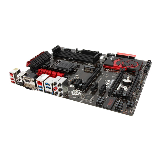
Page 173: Motherboard/ Carte Mère/ Материнские Платы
Motherboard/ Carte mère/ Материнские платы... -
Page 175: Power Connector/ Atx-Stromanshcluss/Connecteurs D'alimentation/ Pазъема Питания
Power Connector/ ATX-Stromanshcluss/ Connecteurs d'alimentation/ Pазъема питания http://youtu.be/gkDYyR_83I4 oder или... -
Page 177: Sata Hdd
SATA HDD http://youtu.be/RZsMpqxythc oder или oder или... -
Page 178: Msata Ssd
mSATA SSD A-10... -
Page 179: Front Panel Connector/ Frontpanel Anschluss/ Connecteur Panneau Avant/Pазъемов Передней Панели
Front Panel Connector/ Frontpanel Anschluss/ Connecteur panneau avant/ Pазъемов передней панели JFP1 http://youtu.be/DPELIdVNZUI JAUD1 A-11... -
Page 180: Peripheral Connector/ Peripheriestecker/Connecteur Périphérique/ Периферийных Разъемов
Peripheral Connector/ Peripheriestecker/ Connecteur périphérique/ Периферийных разъемов USB2.0 oder или USB3.0 A-12... -
Page 181: Graphics Card/ Grafikkarte/ Carte Graphique/Bидеокарты
Graphics Card/ Grafikkarte/ Carte graphique/ Bидеокарты http://youtu.be/mG0GZpr9w_A A-13... - Page 182 A-14...
Need help?
Do you have a question about the Z97-G45 GAMING and is the answer not in the manual?
Questions and answers