Table of Contents
Advertisement
Available languages
Available languages
Advertisement
Table of Contents

Related Manuals for MSI Z97 XPOWER AC


Summary of Contents for MSI Z97 XPOWER AC
- Page 1 Preface Z97 XPOWER AC Motherboard G52-79141X3...
- Page 2 Copyright Notice The material in this document is the intellectual property of MICRO-STAR INTERNATIONAL. We take every care in the preparation of this document, but no guarantee is given as to the correctness of its contents. Our products are under continual improvement and we reserve the right to make changes without notice.
- Page 3 If a problem arises with your system and no solution can be obtained from the user’s manual, please contact your place of purchase or local distributor. Alternatively, please try the following help resources for further guidance. Visit the MSI website for technical guide, BIOS updates, driver updates, and other information: http://www.msi.com/service/download/ Contact our technical staff at: http://register.msi.com/...
- Page 4 Safety Instructions ■ Always read the safety instructions carefully. ■ Keep this User’s Manual for future reference. ■ Keep this equipment away from humidity. ■ Lay this equipment on a reliable flat surface before setting it up. ■ The openings on the enclosure are for air convection hence protects the equipment from overheating.
- Page 5 FCC-B Radio Frequency Interference Statement This equipment has been tested and found to comply with the limits for a Class B digital device, pursuant to Part 15 of the FCC Rules. These limits are designed to provide reasonable protection against harmful interference in a residential installation. This equipment generates, uses and can radiate radio frequency energy and, if not installed and used in accordance with the instructions, may cause harmful interference to radio communications.
- Page 6 Radiation Exposure Statement This equipment complies with FCC radiation exposure limits set forth for an uncontrolled environment. This equipment and its antenna should be installed and operated with minimum distance 20 cm between the radiator and your body. This equipment and its antenna must not be co-located or operating in conjunction with any other antenna or transmitter.
- Page 7 Replace only with the same or equivalent type recommended by the manufacturer. Chemical Substances Information In compliance with chemical substances regulations, such as the EU REACH Regulation (Regulation EC No. 1907/2006 of the European Parliament and the Council), MSI provides the information of chemical substances in products at: http://www.msi.com/html/popup/csr/evmtprtt_pcm.html Preface...
- Page 8 MSI will comply with the product take back requirements at the end of life of MSI-branded products that are sold into the EU. You can return these products to local collection points.
- Page 9 MSI će poštovati zahtev o preuzimanju ovakvih proizvoda kojima je istekao vek trajanja, koji imaju MSI oznaku i koji su prodati u EU. Ove proizvode možete vratiti na lokalnim mestima za prikupljanje.
- Page 10 MSI si adeguerà a tale Direttiva ritirando tutti i prodotti marchiati MSI che sono stati venduti all’interno dell’Unione Europea alla fine del loro ciclo di vita.
-
Page 11: Table Of Contents
CONTENTS ▍ English ...................... En-1 Motherboard Specifications ................En-2 Connectors Quick Guide ..................En-5 Back Panel Quick Guide ..................En-7 CPU (Central Processing Unit) ................En-9 Memory ......................En-13 Mounting Screw Holes ..................En-14 Power Supply ....................En-15 Expansion Slots ....................En-16 Video/ Graphics Cards ..................En-17 Internal Connectors ..................En-18 Voltage Checkpoints ..................En-25 Buttons ......................En-26 Jumper ......................En-30... - Page 12 Guide rapide du panneau arrière ................Fr-7 Mémoire ......................Fr-13 Trous Taraudés de Montage ................Fr-14 Connecteurs d’alimentation ................Fr-15 Emplacements d’extension ................Fr-16 Cartes Vidéo/ Graphics ..................Fr-17 Connecteurs internes ..................Fr-18 Point de vérification tension ................Fr-25 Boutons ......................Fr-26 Cavaliers ......................Fr-30 Cavaliers ......................Fr-31 Indicateurs d'état LED ..................Fr-34 Pilotes et Utilitaires ....................Fr-36 Configuration BIOS ...................Fr-37 Русский...
- Page 13 Pазъемов передней панели ................A-11 Peripheral Connector/ Peripheriestecker/ Connecteur périphérique/ Периферийных разъемов ......................A-12 Graphics Card/ Grafikkarte/ Carte graphique/ Bидеокарты ......A-13 xiii Preface...
-
Page 15: English
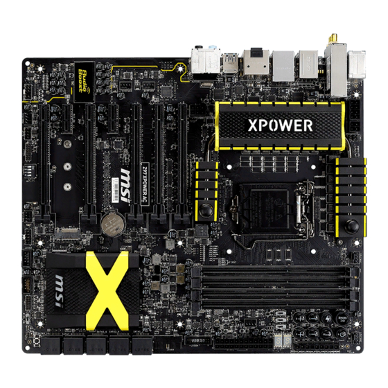
English Thank you for choosing the Z97 XPOWER AC Series (MS-7914 v1.X) E-ATX motherboard. The Z97 XPOWER AC Series motherboards are based on Intel Z97 chipset for optimal system efficiency. Designed to fit the advanced ® Intel LGA1150 processor, the Z97 XPOWER AC Series motherboards ®... -
Page 16: Motherboard Specifications
USB connectors*) ■ ASMedia ASM1074 Chipset - 6x USB 3.0 ports on the back panel ■ ASMedia ASM1042 Chipset - 2x USB 3.0 ports on the back panel * Internal JUSB1 connector supports MSI Super Charger. En-2... - Page 17 Audio ■ Realtek ALC1150 Codec ® - 7.1-Channel High Definition Audio - Supports S/PDIF output ■ 1x Intel I218-V Gigabit LAN controller Wireless ■ Wi-Fi/Bluetooth expansion module with Intel Dual Band Wireless- AC 7260 chip. - Supports Wi-Fi 802.11 a/b/g/n/ac, dual band (2.4GHz, 5GHz) up to 867 Mbps speed.
- Page 18 ■ Super Charger ■ Smart Utilities ■ Wi-Fi ■ Bluetooth ■ Command Center ■ ECO Center Software ■ Drivers ■ MSI - Command Center - Live Update 6 - Smart Utilities - Super Charger - Fast Boot - ECO Center ■ 7-ZIP ■...
-
Page 19: Connectors Quick Guide
SATA7_8 PCI_E6 SATA9_10 M2_1 PCI_E7 FASTB1 1 2 3 4 JAUD1 JCI1 SYSFAN3 BIOS_SW1 JUSB1 JFP2 JUSB2 JTPM1 JFP1 PEGSW1 OPTFAN1 For the latest information about CPU, please visit http://www.msi.com/cpu-support/ For more information on compatible components, please visit http://www.msi.com/test-report/ En-5... - Page 20 Connectors Reference Guide Port Name Port Type Page Back Panel En-7 BCLK+, BCLK- Base Clock Control Buttons En-28 BCLK_STEP1 Base Clock Step Swtich En-33 LGA1150 CPU Socket En-9 CPUFAN1~2,SYSFAN1~3,OPTFAN1~2: Fan Power Connectors En-19 DIMM1~4 Memory Slots En-13 DISCH1 Discharge Button En-27 FASTB1 GO2BIOS Button...
-
Page 21: Back Panel Quick Guide
Back Panel Quick Guide Optical PS/2 Keyboard/ S/PDIF-Out Mouse Combo LAN Port Port Line-In RS-Out Clear CMOS HDMI Button Line-Out CS-Out SS-Out USB 2.0 Port USB 3.0 Port DisplayPort USB 3.0 Port ▶ PS/2 Keyboard/Mouse Combo Port A combination of PS/2 mouse/keyboard DIN connector for a PS/2 mouse/keyboard. - Page 22 ® ▶ HDMI Port The High-Definition Multimedia Interface (HDMI) is an all-digital audio-video interface that is capable of transmitting uncompressed streams. HDMI supports all types of TV formats, including standard, enhanced, or high-definition video, plus multi-channel digital audio on a single cable. ▶...
-
Page 23: Cpu (Central Processing Unit
This motherboard is designed to support overclocking. Before attempting to overclock, please make sure that all other system components can tolerate overclocking. Any attempt to operate beyond product specifications is not recommend. MSI does not guarantee the damages or risks caused by inadequate operation beyond product specifications. - Page 24 CPU & Heatsink Installation When installing a CPU, always remember to install a CPU heatsink. A CPU heatsink is necessary to prevent overheating and maintain system stability. Follow the steps below to ensure correct CPU and heatsink installation. Wrong installation can damage both the CPU and the motherboard.
- Page 25 3. Align the notches with the socket alignment keys. Lower the CPU straight down, without tilting or sliding the CPU in the socket. Inspect the CPU to check if it is properly seated in the socket. 4. Close and slide the load plate under the retention knob. Close and engage the load lever.
- Page 26 7. Locate the CPU fan connector on the motherboard. 8. Place the heatsink on the motherboard with the fan’s cable facing towards the fan connector and the fasteners matching the holes on the motherboard. CPU fan connector 1 2 3 4 9.
-
Page 27: Memory
Memory These DIMM slots are used for installing memory modules. DIMM1 DIMM2 DIMM3 DIMM4 1 2 3 4 Video Demonstration Watch the video to learn how to install memories at the address below. http://youtu.be/76yLtJaKlCQ Dual-Channel mode Population Rule In Dual-Channel mode, the memory modules can transmit and receive data with two data bus channels simultaneously. -
Page 28: Mounting Screw Holes
Mounting Screw Holes When installing the motherboard, first install the necessary mounting stands required for an motherboard on the mounting plate in your computer case. If there is an I/O back plate that came with the computer case, please replace it with the I/O backplate that came with the motherboard package. -
Page 29: Power Supply
Power Supply Video Demonstration Watch the video to learn how to install power supply connectors. http://youtu.be/gkDYyR_83I4 JPWR1~4: ATX Power Connectors These connectors allow you to connect an ATX power supply. To connect the ATX power supply, align the power supply cable with the connector and firmly press the cable into the connector. -
Page 30: Expansion Slots
Expansion Slots This motherboard contains numerous slots for expansion cards, such as discrete graphics or audio cards. PCI_E1~7: PCIe Expansion Slots The PCIe slot supports the PCIe interface expansion card. PCIe 3.0 x16 Slot PCIe 2.0 x1 Slot PCIe x16 Slots Bandwidth Table The table below shows the correlation between the PCIe slots bandwidth and multiple graphics cards. -
Page 31: Video/ Graphics Cards
Adding on one or more discrete video cards will significantly boost the system’s graphics performance. For best compatibility, MSI graphics cards are recommended. Video Demonstration Watch the video to learn how to install a graphics card on PCIe x16 slot with butterfly lock. -
Page 32: Internal Connectors
Internal Connectors SATA1~10: SATA Connectors This connector is a high-speed SATA interface port. Each connector can connect to one SATA device. SATA devices include disk drives (HDD), solid state drives (SSD), and optical drives (CD/ DVD/ Blu-Ray). Video Demonstration Watch the video to learn how to Install SATA HDD. http://youtu.be/RZsMpqxythc SATA2 SATA1... - Page 33 CPUFAN1~2,SYSFAN1~3,OPTFAN1~2: Fan Power Connectors The fan power connectors support system cooling fans with +12V. If the motherboard has a System Hardware Monitor chipset on-board, you must use a specially designed fan with a speed sensor to take advantage of the CPU fan control. Remember to connect all system fans.
- Page 34 JFP1, JFP2: System Panel Connectors These connectors connect to the front panel switches and LEDs. The JFP1 connector is compliant with the Intel Front Panel I/O Connectivity Design Guide. When ® installing the front panel connectors, please use the optional M-Connector to simplify installation.
- Page 35 • Please only connect one device per USB port to ensure stable charging. • Super-Charger Technology is only available on select MSI motherboard models. Please refer to the MSI website to check if your motherboard has Super-Charger technology. • For iPad, JUSB1 (red mark) can still charge iPad in S3, S4, S5 state.
- Page 36 JUSB3: USB 3.0 Expansion Connector The USB 3.0 port is backwards compatible with USB 2.0 devices. It supports data transfer rates up to 5Gbits/s (SuperSpeed). 1 2 3 4 Important • Note that the VCC and GND pins must be connected correctly to avoid possible damage.
- Page 37 JAUD1: Front Panel Audio Connector This connector allows you to connect the front audio panel located on your computer case. This connector is compliant with the Intel Front Panel I/O Connectivity Design ® Guide. 1 2 3 4 M2_1: M.2 Port The M.2 port supports either M.2 SATA 6Gb/s module or M.2 PCIe module.
- Page 38 JTPM1: TPM Module Connector This connector connects to a TPM (Trusted Platform Module). Please refer to the TPM security platform manual for more details and usages. 1 2 3 4 En-24...
-
Page 39: Voltage Checkpoints
Voltage Checkpoints These voltage checkpoints are used to measure the current system voltages. A multimeter (not included) will be required to check voltages. FV1: V-Check Connectors To check the voltage, please use the optional voltage checkpoint cables included in the motherboard package. Attach the positive lead of the multimeter to the voltage checkpoint cable and the negative lead to the ground connector. -
Page 40: Buttons
BIOS section of the manual for instructions on how to turn off OC Genie from the BIOS. • The usage of OC Genie is at the user’s own risk. Overclocking is never guaranteed by MSI. • To ensure successfully OC Genie usage, MSI components are recommended. En-26... - Page 41 POWER1: Power Button This button is used to turn-on and turn-off the system. Press the button once to turn-on or turn-off the system. 1 2 3 4 RESET1: Reset Button This reset button is used to reset the system. Press the button to reset the system. 1 2 3 4 DISCH1: Discharge Button This button allows you to discharge the motherboard by using the button instead of...
- Page 42 BCLK+, BCLK-: Base Clock Control Buttons These buttons are used to increase or decrease the base clock frequency. Pressing the Plus/ Minus button once will increase/ decrease the base clock frequency 1 MHz when the system is in regular operation state. Plus button: Minus button: Base clock + 1 MHz...
- Page 43 FASTB1: GO2BIOS Button If you enable the "MSI Fast Boot" feature in BIOS, the keyboard will be unavaiable and entering BIOS Setup by pressing DEL will not function. Therefore, you can press this button to enter BIOS Setup after reboot.
-
Page 44: Jumper
Jumper JBAT1: Clear CMOS Jumper There is CMOS RAM onboard that is external powered from a battery located on the motherboard to save system configuration data. With the CMOS RAM, the system can automatically boot into the operating system (OS) every time it is turned on. If you want to clear the system configuration, set the jumpers to clear the CMOS RAM. -
Page 45: Switch
Preparation: 1. Prepare a bootable USB flash drive. 2. Download the latest BIOS file from the MSI official website at www.msi.com, and then decompress the file. 3. Copy the AFUDE238.exe and the BIOS file to the bootable USB flash drive BIOS recovery steps: 1. - Page 46 OC_SW1: OC Genie Mode Switch This swtich provides two overclocking modes (Gear 1 and Gear 2) for OC Genie operation. When you press the OC Genie button, the overclocking procedure will be performed according to the setting of this switch. The Gear 1 Mode is the default setting.
- Page 47 BCLK_STEP1: Base Clock Step Swtich This swtich provides two steps (1 MHz and 0.1 MHz) for the operation of Base Clock Control Buttons. Step B: 1MHz Step A: 0.1MHz (Default) 1 2 3 4 PEGSW1: PCIe CeaseFire Switch The PCIe CeaseFire switch can help you conveniently and directly control the installed graphics cards without removing the physical graphics cards.
-
Page 48: Led Status Indicators
LED Status Indicators OC Switch Gear 2 LED Debug LED OC Switch Gear 1 LED MSI LED 1 2 3 4 BIOS A LED HDD LED BIOS B LED LED Status Table The following table describes the status of LED indicators. - Page 49 Debug Code LED Table Please refer to the table below to get more information about the Debug Code LED message. Post Status 02,07 Power on CPU Initialization 03,08 Power on North Bridge Initialization 04,09 Power on South Bridge Initialization Power on Cache Initialization 11~14,32~36,56~5A Early CPU Initialization 15~18,37~3A...
-
Page 50: Drivers And Utilities
After you install the operating system you will need to install drivers to maximize the performance of the new computer you just built. MSI motherboard comes with a Driver Disc. Drivers allow the computer to utilize your motherboard more efficiently and take advantage of any special features we provide. -
Page 51: Bios Setup
"MSI Fast Boot" utility screen. Important • Please be sure to install the “MSI Fast Boot” utility before using it to enter the BIOS setup. • The items under each BIOS category described in this chapter are under continuous update for better system performance. Therefore, the description may be slightly different from the latest BIOS and should be held for reference only. - Page 52 Overview After entering BIOS, the following screen is displayed. Temperature monitor My Favorites Language System XMP Button information Boot device priority bar Virtual OC Genie Button BIOS menu BIOS menu selection selection Menu display ▶ BIOS menu selection The following options are available: ■...
- Page 53 Enables or disables the OC Genie function by clicking on this button. When enabled, this button will be light. Enabling OC Genie function can automatically overclock with MSI optimized overclocking profile. Important We recommend that you do not to make any modification in OC menu mode and do not to load defaults after enabling the OC Genie function.
- Page 54 Operation You can control BIOS settings with the mouse and the keyboard. The following table lists and describes the hot keys and the mouse operations. Hot key Mouse Description <↑↓→← > Select Item Move the cursor <Enter> Select Icon/ Field Click/ Double-click the left button <Esc>...
- Page 55 OC Menu This menu is for advanced users who want to overclock the mainboard. Important • Overclocking your PC manually is only recommended for advanced users. • Overclocking is not guaranteed, and if done improperly, can void your warranty or severely damage your hardware.
- Page 56 Enables the OC Genie function by virtual button in BIOS or physical button on motherboard. Enabling OC Genie function can automatically overclock the system with MSI optimized overclocking profile. [By BIOS Options] OC Genie function is enabled by clicking the virtual OC Genie button at the top left corner of BIOS setup screen.
- Page 57 ▶ Adjust Ring Ratio [Auto] Sets the ring ratio. The valid value range depends on the installed CPU. ▶ Adjusted Ring Frequency Shows the adjusted Ring frequency. Read-only. ▶ Adjust GT Ratio [Auto] Sets the integrated graphics ratio. The valid value range depends on the installed CPU.
- Page 58 ▶ Filter PLL [Auto]* Enables or disables the filter PLL for CPU. This item appears when the installed CPU supports this setting. [Auto] This setting will be configured automatically by BIOS. [Enabled] Provides wide range of base clock for overclocking when base clock strap be set to higher value.
- Page 59 ▶ Advanced DRAM Configuration Press <Enter> to enter the sub-menu. This sub-menu will be activated after setting [Link] or [Unlink] in “DRAM Timing Mode”. User can set the memory timing for each memory channel. The system may become unstable or unbootable after changing memory timing.
- Page 60 ▶ CPU Under Voltage Protection [Auto] Sets the voltage limit for CPU under-voltage protection. If set to "Auto", BIOS will configure this setting automatically. Higher voltage provides less protection and may damage the system. ▶ CPU Over Current Protection [Auto] Sets the current limit for CPU over-current protection.
- Page 61 ▶ DRAM Switching Frequency [Auto] Sets the PWM working speed to stabilize DRAM voltage and minimize ripple range. If set to "Auto", BIOS will configure this setting automatically. ▶ DRAM VRM Over Temperature Protection [Auto] Sets the temperature limit on DRAM VRM for over-temperature protection. The DRAM frequency may be throttled when DRAM VRM over the specified temperature.If set to "Auto", BIOS will configure this settings.
- Page 62 ▶ CPU Core/Ring/GT Voltage Mode [Auto]* Selects the control mode for CPU Core/ Ring/ GT voltages. [Auto] This setting will be configured automatically by BIOS. [Adaptive Mode] Sets the adaptive voltage automatically for optimizing the system performance. [Override Mode] Allows you to set the voltage manually. [Offset Mode] Allows you to set the offset voltage and select the voltage offset mode.
- Page 63 ▶ DRAM/ DDR XXX/ PCH XXX/ XXX Voltage [Auto] Sets the voltages related to memory/ PCH. If set to "Auto", BIOS will set the voltage automatically or you can set it manually. < Other Setting > ▶ CPU Memory Changed Detect [Enabled]* Enables or disables the system to issue a warning message during boot when the CPU or memory has been replaced.
- Page 64 ▶ Execute Disable Bit [Enabled] Intel’s Execute Disable Bit functionality can prevent certain classes of malicious “buffer overflow” attacks where worms attempt to execute code to damage the system. It is recommended that keeps this item enabled always. [Enabled] Enables NO-Execution protection to prevent the malicious attacks and worms.
- Page 65 ▶ C1E Support [Disabled] Enables or disables the C1E function for power-saving in halt state. This item appears when "Intel C-State" is enabled. [Enabled] Enables C1E function to reduce the CPU frequency and voltage for power-saving in halt state. [Disabled] Disables this function.
- Page 66 ▶ Internal VR OVP OCP Protection [Auto] Enables or disables the over-voltage protection and over-current protection for CPU internal VR (Voltage Regulator). [Auto] This setting will be configured automatically by BIOS. [Enabled] Sets the voltage limit on the CPU internal VR for over-voltage protection and over-current protection.
-
Page 67: Deutsch
Deutsch Danke, dass Sie das Z97 XPOWER AC (MS-7914 v1.X) E-ATX Motherboard gewählt haben. Diese Z97 XPOWER AC Motherboard basiert auf dem Intel Z97 Chipsatz und ermöglicht so ein optimales und effizientes System. ® Entworfen, um den hochentwickelten Intel LGA1150 Prozessor zu ®... -
Page 68: Spezifikationen
Spezifikationen Prozessor ■ Die Intel Core™ Prozessoren der 4. und 5. Generation und ® Intel Pentium und Celeron Prozessoren für LGA 1150 Sockel ® ® ® Chipsatz ■ Intel Z97 Express Chipsatz ® Speicher ■ 4x DDR3 Speicherplätze unterstützen bis zu 32GB ■... - Page 69 ■ ASMedia ASM1074 Chipsatz - 6x USB 3.0 Anschlüsse an der rückseitigen Anschlussleiste ■ ASMedia ASM1042 Chipsatz - 2x USB 3.0 Anschlüsse an der rückseitigen Anschlussleiste * Interner JUSB1 Anschluss unterstützt MSI Super Charger. Audio ■ Realtek ALC1150 Codec ®...
- Page 70 ■ Super Charger ■ SMART-Funktion ■ Wi-Fi ■ Bluetooth ■ Kommandozentrale ■ ECO Center Software ■ Treiber ■ MSI - Kommandozentrale - Live Update 6 - SMART-Funktion - Super Charger - Fast Boot - ECO Center ■ 7-ZIP ■ Intel Extreme Tuning Utility ■...
-
Page 71: Anschlussübersicht
PCI_E5 SATA7_8 PCI_E6 SATA9_10 M2_1 PCI_E7 FASTB1 1 2 3 4 JAUD1 JCI1 SYSFAN3 BIOS_SW1 JUSB1 JFP2 JUSB2 JTPM1 JFP1 PEGSW1 OPTFAN1 Weitere CPU Informationen finden Sie unter http://www.msi.com/cpu-support/ Die neusten Informationen über kompatible Bauteile finden Sie unter http://www.msi.com/test-report/ De-5... - Page 72 Übersicht der Motherboard-Anschlüsse Port-Name Port-Typ Seite Rücktafel De-7 BCLK+, BCLK- Grundtaktsteuerung Taste De-28 BCLK_STEP1 Grundtakt Stufenschalter De-33 LGA1150 CPU Sockel De-9 CPUFAN1~2,SYSFAN1~3,OPTFAN1~2: Stromanschlüsse für Lüfter De-19 DIMM1~4 Speichersteckplätze De-13 DISCH1 Entladetaste De-27 FASTB1 GO2BIOS Taste De-29 Spannungsmesspunkte De-25 JAUD1 Audioanschluss des Frontpanels De-23 JBAT1 Steckbrücke zur CMOS-Löschung...
-
Page 73: Rücktafel-Übersicht
Rücktafel-Übersicht Optischer S/PDIF- PS/2 Tastatur/ Ausgang Maus Combo Anschluss Anschluss Line-In RS-Out Clear CMOS HDMI Button Line-Out CS-Out SS-Out USB 2.0 USB 3.0 Anschluss DisplayPort USB 3.0 Anschluss Anschluss ▶ PS/2 Tastatur/Maus Combo Anschluss Die Standard PS/2 Maus/Tastatur Stecker DIN ist für eine PS/2 Maus/Tastatur. - Page 74 ® ▶ HDMI Anschluss Das High-Definition Multimedia Interface (kurz HDMI) ist eine Schnittstelle für die volldigitale Übertragung von dekomprimierten Audio- und Video-Daten. Dieser HDMI unterstützt alle Formate für Fernsehen, einschließlich Standard- und Enhanced- oder HD-Video sowie das Audioformate der Unterhaltungselektronik. ▶...
-
Page 75: Cpu (Prozessor
CPU (Prozessor) Erklärung zur LGA 1150 CPU Die Obserseite der LGA 1150 CPU hat zwei Justierungen und ein gelbes Dreieck um die korrekte Ausrichtung der CPU auf dem Motherboard zu gewährleisten. Das gelbe Dreieck des Prozessors definiert die Position des ersten Pins. Kerbe Kerbe Das goldene Dreieck des Prozessors... - Page 76 CPU & Kühlkörper Einbau Wenn Sie die CPU einbauen, denken sie bitte daran einen CPU-Kühler zu installieren. Ein CPU-Kühlkörper ist notwendig, um eine Überhitzung zu vermeiden und die Systemstabilität beizubehalten. Befolgen Sie die nachstehenden Schritte, um die richtige CPU und CPU-Kühlkörper Installation zu gewährleisten. Ein fehlerhafter Einbau führt zu Schäden an der CPU und dem Motherboard.
- Page 77 3. Positionieren Sie die Kerben mit die Justiermarkierungen des Sockels. Setzen Sie die CPU nach unten, ohne Kippen oder Schieben der CPU im Sockel. Begutachten Sie, ob die CPU richtig im Sockel sitzt. 4. Schließen Sie und schieben Sie die Abdeckplatte unter dem Rückhalteknopf. Verschließen Sie den Verschlusshebel.
- Page 78 7. Machen Sie den CPU-Lüfteranschluss auf dem Motherboard ausfinding. 8. Setzen Sie den Kühlkörper auf die CPU und beachten Sie die Übereinstimmung der Lüfterverankerungen mit den dafür vorgsehenen Löchern auf der Motherboard -Platine. CPU-Lüfteranschluss 1 2 3 4 9. Drücken Sie nach der korrekten Positionierung des Kühlkörpers die Arretierungsstifte mit leichtem Druck nach unten bis sie einrasten.
-
Page 79: Speicher
Speicher Die DIMM-Steckplätze nehmen Arbeitsspeichermodule auf. DIMM1 DIMM2 DIMM3 DIMM4 1 2 3 4 Video-Demonstration Anhand dieses Video an untenstehender Adresse erfahren Sie, wie Sie die Speichermodule installieren. http://youtu.be/76yLtJaKlCQ Populationsregeln für Dual-Kanal-Speicher Im Dual-Kanal-Modus können Arbeitsspeichermodule Daten über zwei Datenbusleitungen gleichzeitig senden und empfangen. Durch Aktivierung des Dual- Kanal-Modus wird die Leistung Ihres Systems verbessert. -
Page 80: Schraubenlöcher Für Die Montage
Schraubenlöcher für die Montage Verwenden Sie die dem Motherboard beiliegende I/O-Platte und setzen Sie sie mit leichtem Druck von innen in die Aussparung des Computergehäuses ein. Zur Installation des Motherboards in Ihrem PC-Gehäuse befestigen Sie zunächst die dem Gehäuse beiliegenden Abstandhalter im Gehäuse. Legen Sie das Motherboard mit den Schraubenöffnungen über den Abstandhaltern und schrauben Sie das Motherboard mit den dem Gehäuse beiliegenden Schrauben fest. -
Page 81: Stromversorgung
Stromversorgung Video-Demonstration Anhand dieses Video an untenstehender Adresse erfahren Sie, wie Sie die Stromversorgungsstecker installieren. http://youtu.be/gkDYyR_83I4 JPWR1~4: ATX Stromanschlüsse Mit diesem Anschluss verbinden Sie den ATX Stromanschlusse. Achten Sie bei dem Verbinden des ATX Stromanschlusses darauf, dass der Anschluss des Netzteils richtig auf den Anschluss an der Hauptplatine ausgerichtet ist. -
Page 82: Erweiterungssteckplätze
Erweiterungssteckplätze Dieses Motherboard enthält zahlreiche Schnittstellen für Erweiterungskarten, wie diskrete Grafik-oder Soundkarten. PCI_E1~7: PCIe Erweiterungssteckplätze Der PCIe Steckplatz unterstützt PCIe-Erweiterungskarten. PCIe 3.0 x16-Steckplatz PCIe 2.0 x1-Steckplatz PCIe x16 Steckplätze-Bandbreite Tabelle Die nachfolgende Tabelle zeigt den Zusammenhang zwischen der PCIe-Steckplätze Bandbreite und mehreren Grafikkarten. Bandbreite Steckplatz Single... -
Page 83: Video/ Grafikkarten
Video/ Grafikkarten Fall im Prozessor integriert, nutzt dieses Motherboard den im Prozessor befindlichen Grafikprozessor. Zusätzliche Grafikkarten können aber über die auf dem Motherboard verfügbaren Erweiterungssteckplätze eingesetzt werden um die Systemleistung zu erhöhen. Video-Demonstration Anhand dieses Video an untenstehender Adresse erfahren Sie, wie Sie eine Grafikkarte im PCIe x16 Steckplatz mit Butterfly-Verschlüssen installieren. -
Page 84: Interne Anschlüsse
Interne Anschlüsse SATA1~10: SATA Anschlüsse Dieser Anschluss basiert auf der Hochgeschwindigkeitsschnittstelle Serial ATA (SATA). Pro Anschluss kann ein Serial ATA Gerät angeschlossen werden. Zu Serial ATA Geräten gehören Festplatten (HDD), SSD Festplatten (SSD) und optische Laufwerke (CD-/DVD-/Blu-Ray-Laufwerke). Video-Demonstration Anhand dieses Video an untenstehender Adresse erfahren Sie, wie Sie eine SATA-Featplatte installieren. - Page 85 CPUFAN1~2,SYSFAN1~3,OPTFAN1~2: Stromanschlüsse für Lüfter Die Anschlüsse unterstützen aktive Systemlüfter mit +12V. Ist Ihr Motherboard mit einem Chipsatz zur Überwachung der Systemhardware versehen, dann brauchen Sie einen speziellen Lüfter mit Geschwindigkeitsregelung, um die Vorteile der Steuerung des CPU Lüfters zu nutzen. Vergessen Sie nicht, alle Systemlüftern anzuschließen. Einige Systemlüfter können nicht direkt an dem Motherboard angeschlossen werden und müssen stattdessen mit dem Netzteil direkt verbunden werden.
- Page 86 JFP1, JFP2: Systemtafelanschlüsse Diese Anschlüsse sind für das Frontpanel angelegt. Sie dienen zum Anschluss der Schalter und LEDs des Frontpanels. JFP1 erfüllt die Anforderungen des “Intel Front ® Panel I/O Connectivity Design Guide”. Bei der Installation des Frontpanel-Anschlüsse, nutzen Sie bitte die optionalen M-Connectors um die Installation zu vereinfachen. Schließen Sie alle Kabel aus dem PC-Gehäuse zunächst an die M-Connectors an und stecken Sie die M-Connectors auf das Motherboard.
- Page 87 Ladevorgang. • Die Super-Charger Technologie ist nur für ausgewählte MSI Motherboard-Modelle verfügbar. Prüfen Sie bitte anhand der MSI Webseite ob Ihr Motherboard die SuperCharger Technologie unterstützt. • Das iPad kann auch im S3-, S4- und S5-Status über den JUSB1 (rote Markierung) geladen werden.
- Page 88 JUSB3~4: USB 3.0 Erweiterungsanschlüsse Der USB 3.0 Anschluss ist abwärtskompatibel mit USB 2.0-Geräten. Unterstützt Datentransferraten bis zu 5 Gbit/s (SuperSpeed). 1 2 3 4 Wichtig • Bitte beachten Sie, dass Sie die mit VCC (Stromführende Leitung) und GND (Erdleitung) bezeichneten Pins korrekt verbinden müssen, ansonsten kann es zu Schäden kommen.
- Page 89 JAUD1: Audioanschluss des Frontpanels Dieser Anschluss ermöglicht den Anschluss von Audio Ein- und Ausgängen eines Frontpanels. Der Anschluss entspricht den Richtlinien des “ Intel Front Panel I/O ® Connectivity Design Guide”. 1 2 3 4 M2_1: M.2-Port Der M.2-Port unterstützt entweder ein M.2 SATA 6Gb/s-Modul oder ein M.2 PCIe- Modul.
- Page 90 JTPM1: TPM Anschluss Dieser Anschluss wird für das TPM Modul (Trusted Platform Module) verwendet. Weitere Informationen über den Einsatz des optionalen TPM Modules entnehmen Sie bitte dem TPM Plattform Handbuch. 1 2 3 4 De-24...
-
Page 91: Spannungsmesspunkte
Spannungsmesspunkte Die Spannungsmesspunkte werden verwendet, um die aktuelle Systemspannung zu messen. Ein Multimeter (nicht enthalten) wird für die Spannungsmessung benötigt. FV1: Spannungsmess-Anschluss Um die Spannung zu prüfen, verwenden Sie die Spannungsmesspunkte des Motherboards. Halten Sie die positive Leitung des Multimeters an den Spannungsanschluss und die negative Leitung an den Erdungspol. -
Page 92: Tasten
• Bitte installieren Sie DDR3 1333 oder schnelleren Hauptspeicher sowie hochwertige Kühler wenn Sie OC Genie einsetzen. • MSI gibt keine Garantie auf den Übertaktungsbereich und auf eventuelle Schäden, die durch eine Übertaktung entstehen können. • OC Genie kann im BIOS deaktiviert werden. Der BIOS-Bereich dieses Handbuchs gibt darüber Auskunft. - Page 93 POWER1: Ein-/Ausschalter Dieser Ein-/ Ausschalter wird verwendet, um das System ein- und auszuschalten. Drücken Sie diese Taste, um das System ein- bzw. auszuschalten. 1 2 3 4 RESET1: Reset-Taste Diese Reset-Taste wird verwendet, um das System zurückzusetzen. Drücken Sie die Taste, um das System zurückzusetzen.
- Page 94 BCLK+, BCLK-: Grundtaktsteuerung Taste Diese Tasten werden benutzt, um die Grundtaktfrenquenz zu erhöhen oder zu verringern. Drücken Sie die Plus-/ Minus-Tasten einmal, um die Grundtaktfrenquenz 1 MHz oder 0,1 MHz zu erhöhen/ verringern, wenn das System im regelmäßigen Betriebszustand ist. Plus Taste: Minus Taste: Grundtakt + 1 MHz...
- Page 95 FASTB1: GO2BIOS Taste Wenn Sie die “MSI Fast Boot”-Funktion im BIOS aktivieren, wird es in den meisten Fällen nicht gelingen, mittels rechtzeitigem Drücken der Del-Taste ins BIOS Setup- Menü zu gelangen. Daher können Sie vor dem Start die G2BIOS Taste drücken, um nach dem Neustart automatisch das BIOS-Setup zu öffnen.
-
Page 96: Steckbrücken
Steckbrücken JBAT1: Steckbrücke zur CMOS-Löschung Der Onboard CMOS Speicher (RAM) wird durch eine externe Spannungsversorgung durch eine Batterie auf dem Motherboard versorgt, um die Daten der Systemkonfiguration zu speichern. Er ermöglicht es dem Betriebssystem, mit jedem Einschalten automatisch hochzufahren. Wenn Sie die Systemkonfiguration löschen wollen, müssen Sie die Steckbrücke für kurze Zeit umsetzen. -
Page 97: Schalter
Schritten wieder hergestellt werden Vorbereitung: 1. Bereiten Sie einen boot-fähigen USB-Stick vor 2. Laden Sie das neueste BIOS von der offiziellen MSI website bei www.msi.com herunter und entpacken Sie die Datei. 3. Kopieren Sie AFUDE238.exe und die BIOS-Datei auf den USB-Stick. - Page 98 OC_SW1: OC Genie Modeschalter Dieser Schalter bietet zwei Übertaktung-Modi (Gear 1 und Gear 2) für den OC Genie Betrieb. Wenn Sie die OC Genie-Taste drücken, wird die Übertaktung nach der Einstellung dieses Schalters ausgeführt. Der Gear 1 Modus ist die Standardeinstellung.
- Page 99 BCLK_STEP1: Grundtakt Stufenschalter Dieser Schalter bietet zwei Schritten (1 MHz und 0,1 MHz) für den Betrieb von der Grundtaktsteuerung Taste. Schritt B: 1MHz Schritt A: 0.1MHz (Standardwert) 1 2 3 4 PEGSW1: PCIe CeaseFire Schalter Mit dem PCIe CeaseFire Schalter können Sie die installierten Grafikkarten bequem und direkt steuern, ohne die physikalischen Grafikkarten zu entfernen.
-
Page 100: Led Statusanzeige
LED Statusanzeige OC Schalter Gear 2 LED Debug LED OC Schalter Gear 1 LED MSI LED 1 2 3 4 BIOS A LED HDD LED BIOS B LED Die Tabelle der LED Statusanzeigen Die folgende Tabelle beschreibt die Bedeutung der LED-Anzeigen. - Page 101 Debug-Code-LED-Panel Weitere Informationen zu den Debug-LED-Meldungen entnehmen Sie bitte der nachstehenden Tabelle. Post Status 02,07 Start-CPU-Initialisierung 03,08 Start-Northbridge-Initialisierung 04,09 Start-Southbridge-Initialisierung Start-Cache-Initialisierung 11~14,32~36,56~5A Frühe CPU-Initialisierung 15~18,37~3A Frühe Northbridge-Initialisierung 19~1C,3B~3E Frühe Southbridge-Initialisierung 1D~2F,31,3F~4E,50~55 Frühe Speicherinitialisierung 63~67,D0 Späte CPU-Initialisierung 69~6F,D1 Späte Northbridge-Initialisierung 70~77,D2 Späte Southbridge-Initialisierung 92~96,B5,D4 PCI-Bus-Initialisierung...
-
Page 102: Treiber Und Dienstprogramme
Treiber und Dienstprogramme Nach der Installation des Betriebssystems müssen Sie Treiber installieren, um die Leistung des neuen Computers zu maximieren. Dem MSI Mainbaord liegt eine Treiber-CD bei. Die enthaltenen Treiber ermöglichen es Ihnen, das Motherboard effizienter zu nutzen und von den besonderen Eigenschaften des MSI Motherboards zu profitieren. -
Page 103: Bios Setup
BIOS Setup CLICK BIOS wurde von MSI entwickelt, es bietet eine intuitiv bedienbare grafische Benutzeroberfläche in der BIOS-Parameter einfach per Maus und Tastatur konfiguriert werden können. Mit CLICK BIOS können Benutzer alle wichtigen BIOS-Einstellungen ändern, die CPU-Temperatur überwachen, die Boot-Reihenfolge festlegen und die Systeminformationen anzeigen, wie CPU-Name, DRAM Kapazität, OS-Version und... - Page 104 Überbilck Nach dem Aufrufen des BIOS, sehen Sie die folgende Anzeige. Temperaturüberwachung Favoriten Sprache System- XMP Taste Information Bootgeräte- Prioritäts- Virtual OC leiste Genie Taste BIOS-Menü- BIOS-Menü- Auswahl Auswahl Menüanzeige ▶ BIOS-Menü-Auswahl Die folgenden Optionen stehen zur Verfügung: ■ SETTINGS - Mit diesem Menü können Sie die Parameter für Chipsatz, Boot- Geräte angeben.
- Page 105 Aktivieren oder deaktivieren Sie die OC Genie Funktion durch einen Klick auf diese Taste. Wenn aktiviert, leuchtet diese Taste auf. Aktivieren Sie die OC Genie-Funktion mit einem von MSI optimierten Übertaktungsprofil automatisch zu übertakten. Wichtig Es wird empfohlen, keine Änderung im OC-Menü zu machen und die Werkseinstellungen nach dem Aktivieren der OC Genie-Funktion nicht zu laden.
- Page 106 Betrieb Sie können die BIOS-Einstellungen mit der Maus oder der Tastatur steuern. Die folgende Tabelle zeigt und beschreibt die Hotkeys und Mausaktionen. Hotkey Maus Beschreibung <↑↓→← > Auswahl eines Eintrages Bewegen Sie den Cursor <Enter> Auswahl eines Symbols/ Feldes Klicken/ doppelt- klicken Sie mit der linken Maustaste <Esc>...
- Page 107 OC-Menü In diesem Menü können Benutzer das BIOS anpassen und übertakten. Bitte führen Sie nur Änderungen durch, wenn Sie sich über das Ergebniss im Klaren sind. Sie sollten Erfahrung beim Übertakten haben, da Sie sonst das Motherboard oder Komponenten des Systems beschädigen können. Wichtig •...
- Page 108 Aktivieren Sie die OC Genie Funktion durch die virtuelle Taste im BIOS oder die physische Taste auf dem Motherboard. Das Aktivieren der OC Genie-Funktion kann das System mit dem von MSI optimierten Übertaktungsprofil automatisch übertakten. [By BIOS Options] Aktivieren Sie die OC Genie Funktion durch einen Klick auf die virtuelle Taste in der linken oberen Ecke des BIOS-Setup- Bildschirm.
- Page 109 Wichtig • Es wird empfohlen, keine Änderung im OC-Menü zu machen und die Werkseinstellungen nach dem Aktivieren der OC Genie-Funktion nicht zu laden. • Im OC Genie Modus sind das BIOS-Update oder ein Clearing-CMOS unzulässig. Diese können zum Versagen der OC Genie Funktion oder zu anderen Effekten führen.
- Page 110 ▶ BCLK Amplitude [Auto]* Die BCLK Amplitude dient der Verstärkung des Signals des CPU BCLK und hat Auswirkungen auf die Extremübertaktung der CPU. Wenn die Einstellung auf [Auto] gesetzt ist, wird das BIOS diese Einstellungen automatisch konfigurieren. ▶ CPU PCIE PLL [Auto]* Wählen Sie einen PLL-Modus (Phase Lock Loop) für die CPU PCIe aus.
- Page 111 ▶ Memory Try It ! [Disabled] Die Option “Memory Try It!” dient der Verbesserung der Speicherkompatibilität oder auch der Speicherleistung durch die Auswahl der optimierten Speicher- Voreinstellungen. ▶ DRAM Timing Mode [Auto] Wählt den Speicher-Timing-Modus aus. [Auto] Das DRAM-Timing wird basierend auf SPD (Serial Presence Detect) der installierten Speichermodule bestimmt.
- Page 112 ▶ VR 12VIN OCP Expander [Auto] Erweitert die Begrenzung des VR-Überstromschutz mit 12V Eingangsspannung. Höherer ausweitenden Wert kann auf wenigen Schutz hindeuten. Bitte passen Sie deshalb den Strom sorgfältig an, um Beschädigungen des CPU/ VR MOS zu vermeiden. Wenn die Einstellung auf [Auto] gesetzt ist, wird das BIOS diese Einstellungen automatisch konfigurieren.
- Page 113 ▶ CPU Power Duty Control [Thermal Balance] Wählen Sie die Methode der VRM-Steuerung für CPU Phase aus. [Thermal Balance] Steueren Sie die VRM mit dem thermischen Balance-Modus. [Current Balance] Steueren Sie die VRM mit dem aktuellen Balance-Modus. ▶ DRAM Phase Control [Auto] Steueren Sie PWM Phase proportional zur DRAM-Belastung.
- Page 114 ▶ PCH Vdroop Offset Control [Auto] Legen Sie einen Prozentsatz der Offset-Spannung für die PCH VDroop fest. Wenn die Einstellung auf [Auto] gesetzt ist, wird das BIOS diese Einstellungen automatisch konfigurieren.. ▶ PCH Over Voltage Protection [Auto] Legen Sie die Spannungsgrenze für den PCH-Überspannungsschutz fest. Wenn die Einstellung auf [Auto] gesetzt ist, wird das BIOS diese Einstellungen automatisch konfigurieren.
- Page 115 [Override + Offset ] Hier können Sie die Spannung und die Offset-Spannung manuell einstellen. ▶ CPU Core Voltage/ CPU Ring Voltage/ CPU GT Voltage [Auto] Einstellung dieser CPU Core/ Ring/ GT-Spannungen. Wenn die Einstellung auf [Auto] gesetzt ist, wird das BIOS die Spannungen automatisch eingestellt oder Sie können es manuell einstellen.
- Page 116 < Andere Einstellung > ▶ CPU Memory Changed Detect [Enabled]* Aktivierung oder Deaktivierung der Systemwarnmeldung beim Booten, wenn die CPU oder Hauptspeicher ersetzt wurde. [Enabled] Das System zeigt eine Warnmeldung beim Systemstart und lädt die Default-Einstellungen für neue Geräte. [Disabled] Deaktivierung der Funktion und Beibehaltung der aktuellen BIOS- Einstellungen.
- Page 117 ▶ Execute Disable Bit [Enabled] Intel’s Execute Disable Bit kann an den Rechner gerichtete “Buffer Overflow” Angriffe verhindern, bei denen Computer-Würmer versuchen, das System durch Ausführung von Codes zu schädigen. Es wird empfohlen, diese Funktion zu aktivieren. [Enabled] Aktiviert den NO-Execution Schutz, um bösartigen Angriffe und Würmern abzuwehren.
- Page 118 ▶ C1E Support [Disabled] Aktiviert oder deaktiviert die C1E-Funktion für Stromersparnis im Leerlauf. Diese Option wird angezeigt, wenn “Intel C-State” aktiviert ist. [Enabled] Ermöglicht die C1E Funktion, um die CPU-Frequenz und Spannung zur Stromersparnis im Leerlauf zu reduzieren. [Disabled] Deaktiviert diese Funktion. ▶...
- Page 119 ▶ Internal VR OVP OCP Protection [Auto] Aktiviert oder deaktiviert Sie den Überspannungsschutz und Überstromschutz für den CPU internen Spannungsregulator (VR/ Voltage Regulator). [Auto] Diese Einstellungen werden vom BIOS automatisch konfiguriert. [Enabled] Legt die Spannungsbegrenzung der CPU internen VR für Überspannungsschutz und Überstromschutz.
-
Page 121: Français
Français Merci d’avoir choisi une carte mère E-ATX de la série Z97 XPOWER AC (MS- 7914 v1.X). La série Z97 XPOWER AC est basée sur le chipset Intel ® pour une efficacité optimale. Conçue pour fonctionner avec les processeurs Intel LGA1150, les cartes mère de la série Z97 XPOWER AC délivrent de... -
Page 122: Spécifications
USB internes*) ■ Chipset ASMedia ASM1074 - 6x ports USB 3.0 sur le panneau arrière ■ Chipset ASMedia ASM1042 - 2x ports USB 3.0 sur le panneau arrière * Le connecteur JUSB1 interne supporte MSI Super Charger. Fr-2... - Page 123 Audio ■ Realtek ALC1150 Codec ® - 7.1-canal audio haute-définition - Support S/PDIF output ■ 1x Intel I218-V Gigabit LAN Contrôleur Wireless LAN ■ Module d’extension Wi-Fi/Bluetooth avec puces Intel Dual Band Wireless-AC 7260. - Support Wi-Fi 802.11 a/b/g/n/ac, double bandes (2.4GHz, 5GHz) jusqu’à...
- Page 124 ■ Super Charger ■ Smart Utilities ■ Wi-Fi ■ Bluetooth ■ Command Center ■ ECO Center Logiciel ■ Pilotes ■ MSI - Command Center - Live Update 6 - Smart Utilities - Super Charger - Fast Boot - ECO Center ■ 7-ZIP ■...
-
Page 125: Guide Rapide Des Connecteurs
PCI_E6 SATA9_10 M2_1 PCI_E7 FASTB1 1 2 3 4 JAUD1 JCI1 SYSFAN3 BIOS_SW1 JUSB1 JFP2 JUSB2 JTPM1 JFP1 PEGSW1 OPTFAN1 Pour plus d’information sur le CPU, veuillez visiter http://www.msi.com/cpu-support/ Pour plus d’information sur les composants compatibles, veuillez visiter http://www.msi.com/test-report/ Fr-5... - Page 126 Guide référence des connecteurs Noms de ports Types des ports Page Panneau arrière Fr-7 BCLK+, BCLK- Boutons de contrôle de base clock Fr-28 BCLK_STEP1 Interrupteur d'étape de base clock Fr-33 LGA1150 CPU Socket Fr-9 CPUFAN1~2,SYSFAN1~3,OPTFAN1~2: Connecteurs d'alimentation de ventilateurs Fr-19 DIMM1~4 Emplacements de mémoire Fr-13...
-
Page 127: Guide Rapide Du Panneau Arrière
Guide rapide du panneau arrière S/PDIF-Out Port PS/2 optique Combo clavier/ souris Port LAN Ligne-In RS-Out Bouton d’effacement HDMI Ligne-Out CS-Out CMOS SS-Out Port USB 2.0 Port USB 3.0 DisplayPort Port USB 3.0 ▶ Port PS/2 combo clavier/ souris Combinaison d'un connecteur souris / clavier DIN PS/2 pour une souris ou un clavier PS/2 ®... - Page 128 ® ▶ Port HDMI Le High-Definition Multimedia Interface est une interface audio/vidéo tout-numérique, qui est capable de transmettre des flux décompressés. HDMI supporte toutes les formes de TV, y compris le standard, l’amélioré, ou les vidéos hautes définitions, plus l’audio numérique multicanal sur un simple câble. ▶...
- Page 129 Processeur : CPU Introduction du CPU LGA 1150 A la surface du CPU LGA 1150 vous noterez deux encoches et un triangle jaune servant à aligner le CPU dans la bonne position sur la carte mère. Le triangle jaune corresponde à la Pin 1. Encoche Encoche Le triangle jaune corresponde à...
- Page 130 Installation du CPU et son ventilateur Quand vous installez un CPU, assurez-vous toujours que le CPU soit équipé d’un ventilateur, qui est nécessaire pour éviter la surchauffe et maintenir la stabilité. Suivez les instruction suivantes pour installer le CPU et son ventilateur correctement. Une installation incorrecte peut endommager votre CPU et la carte mère.
- Page 131 3. Alignez les encoches et les clés d’alignement du socket. Abaissez le CPU en ligne droite, évitez de faire basculer ou glisser le CPU dans l’emplacement. Vérifiez qu'il est bien installé dans la bonne direction. 4. Fermez et glissez le plaque de charge sous le bouton de rétention. Fermez et engagez le levier de charge.
- Page 132 7. Localisez le connecteur du ventilateur CPU sur la carte mère. 8. Placez le ventilateur sur la carte mère avec son câble face au connecteur du ventilateur. Les éléments de fixation doivent correspondre aux trous sur la carte. Connecteur de ventilateur CPU 1 2 3 4 9.
-
Page 133: Mémoire
Mémoire Ces emplacements DIMM sont destinés à installer les modules de mémoire. DIMM1 DIMM2 DIMM3 DIMM4 1 2 3 4 Démonstration de vidéo Voir le vidéo sur l'installation des mémoires sur le site ci-dessous. http://youtu.be/76yLtJaKlCQ Règle de population en mode double canal En mode de double canal, les modules de mémoire peuvent transmettre et recevoir simultanément deux lignes de données. -
Page 134: Trous Taraudés De Montage
Trous Taraudés de Montage Avant d’installer votre carte mère, il faut d’abord installer les socles de montage néce saires sur le plateau de montage du boîtier de l’ordinateur. Si le boîtier de l’ordinateur est accompagné par un panneau Entrée/ Sortie arrière, veuillez le remplacer et utiliser celui qui est fournit dans la boîte de la carte. -
Page 135: Connecteurs D'alimentation
Connecteurs d’alimentation Démonstration de vidéo Voir le vidéo sur l’installation des connecteurs d’alimentation sur le site ci-dessous. http://youtu.be/gkDYyR_83I4 JPWR1~4 : Connecteur d'alimentation ATX Ce connecteur vous permet de relier une alimentation ATX. Pour cela, alignez le câble d’alimentation avec le connecteur et appuyez fermement le câble dans le connecteur. Si ceci est bien fait, la pince sur le câble d’alimentation doit être accrochée sur le connecteur d’alimentation de la carte mère. -
Page 136: Emplacements D'extension
Emplacements d’extension Cette carte mère contient de nombreux ports pour les cartes d’extension, tels que les cartes graphiques ou les cartes audio. PCI_E1~7 : Emplacement d’extension PCIe L'emplacement PCIe supporte l'interface de carte d'extension PCIe. Emplacement PCIe 3.0 x16 Emplacement PCIe 2.0 x1 Tableau de débit d’emplacements PCIe x16 Ce tableau montre la corrélation entre le débit des emplacements PCIe et les multiples cartes graphiques. -
Page 137: Cartes Vidéo/ Graphics
Une ou plusieurs cartes vidéo ajoutées peuvent améliorer fortement la performance graphique du système. Pour une compatibilité parfaite, nous vous recommandons d’utiliser des cartes graphiques MSI. Démonstration de vidéo Voir le vidéo sur l’installation d’une carte graphique dans l’emplacement PCIe x16 avec verrou papillon sur le site ci-dessous. -
Page 138: Connecteurs Internes
Connecteurs internes SATA1~10 : Connecteurs SATA Ce connecteur est un port d’interface SATA haut débit. Chaque connecteur peut être relié à un appareil SATA. Les appareils SATA sont des disques durs (HDD), disque état solide (SSD), et lecteurs optiques (CD/ DVD/ Blu-Ray). Démonstration de vidéo Voir le vidéo sur l’installation d’un SATA HDD. - Page 139 CPUFAN1~2,SYSFAN1~3,OPTFAN1~2 : Connecteur d’alimentation du ventilateur Les connecteurs d’alimentation du ventilateur supportent les ventilateurs de type +12V. Si la carte mère est équipée d’un moniteur du matériel système intégré, vous devrez utiliser un ventilateur spécial pourvu d’un capteur de vitesse afin de contrôler le ventilateur de l’unité...
- Page 140 JFP1, JFP2 : Connecteur panneau système Ces connecteurs se connectent aux interrupteurs et LEDs du panneau avant. Le JFP1 est conforme au guide de conception de la connectivité Entrée/sortie du panneau avant Intel . Lors de l’installation des connecteurs du panneau avant, veuillez utiliser ®...
- Page 141 • La SuperCharger Technology n’est pas disponible sur tous les modèles de carte mère. Veuillez vous référer au site MSI pour vérifier si votre carte mère est équipé de la SuperCharger Technology. • Pour l’iPad, JUSB1 (marqué rouge) peut aussi charger l’iPad en état S3, S4, S5.
- Page 142 JUSB3~4 : Connecteurs d’extension USB 3.0 Le port USB 3.0 est rétro-compatible avec les périphériques USB 2.0. Il supporte un taux de transfert jusqu’à 5 Gbit/s (Super-Vitesse). 1 2 3 4 Important • Notez que les pins de VCC et GND doivent être branchées correctement afin d’éviter tout dommage possible.
- Page 143 JAUD1 : Connecteur audio panneau avant Ce connecteur vous permet de connecter un audio sur le panneau avant.Il est conforme au guide de conception de la connectivité Entrée/sortie du panneau avant Intel ® 1 2 3 4 M2_1 : Port M.2 Le port M.2 supporte soit le module M.2 SATA 6Gb/s ou celui M.2 PCIe.
- Page 144 JTPM1 : Connecteur de Module TPM Ce connecteur est relié à un module TPM (Trusted Platform Module) en option. Veuillez vous référer au manuel du module TPM pour plus d’information détaillée. 1 2 3 4 Fr-24...
-
Page 145: Point De Vérification Tension
Point de vérification tension Ces points de vérification de tension servent à mesurer les tensions actuelles du système. Un multimètre est nécessaire (non fourni) pour vérifier les tensions. FV1 : Points de contrôle tension Ces points de vérification tension servent à mesurer les tensions du CPU et du PCH. Pour vérifier les tensions, il faut attacher le fil positif du multimètre à... -
Page 146: Boutons
à la section BIOS de ce manuel pour les instructions comment désactiver OC Genie dans le BIOS. • L’utilisation d’OC Genie est à la risque de l’utilisateur. Overclocking n’est jamais garanti par MSI. • Pour assurer un usage réussi d’OC Genie, les composants MSI sont recommandés. Fr-26... - Page 147 POWER1 : Bouton d’alimentation Ce bouton sert à allumer ou éteindre le système. Appuyez sur ce bouton pour allumer ou éteindre le système. 1 2 3 4 RESET1 : Bouton de réinitialisation Ce bouton sert à réinitialiser le système. Appuyez sur ce bouton pour le réinitialiser. 1 2 3 4 DISCH1 : Bouton de décharge Ce bouton vous permet de décharger la carte mère en utilisant ce bouton au lieu...
- Page 148 BCLK+, BCLK- : Bouton de contrôle de base clock Ces boutons servent à augmenter ou baisser la fréquence de base clock. Appuyer sur le bouton Plus/ Minus (Moins) une fois peut augmenter/ baisser la fréquence de base clock de 1 MHz lorsque le système est en état d'opération régulier. Bouton Plus : Bouton Minus (Moins) : Base clock + 1 MHz...
- Page 149 FASTB1 : Bouton GO2BIOS Si vous activez la fonction "MSI Fast Boot" dans le BIOS, le clavier est indisponible et il est impossible d'entrer dans le BIOS en appuyant sur DEL. Une fois que vous appuyez sur ce bouton, le système entrera dans la configuration BIOS directement au prochain démarrage.
-
Page 150: Cavaliers
Cavaliers JBAT1 : Cavalier d’effacement CMOS Il y a un CMOS RAM intégré, qui est alimenté par une batterie externe située sur la carte mère, destiné à conserver les données de configuration du système. Avec le CMOS RAM, le système peut lancer automatiquement le système d’exploitation chaque fois qu’il est allumé. -
Page 151: Cavaliers
BIOS endommagé avec les étapes ci-dessous. Préparation: 1. Préparez une clé USB bootable 2. Téléchargez la dernière version de BIOS depuis le site MSI official www.msi.com, et puis décompressez le fichier. 3. Copier AFUDE238.exe et le fichier BIOS sur la clé USB bootable. - Page 152 OC_SW1 : Interrupteur de mode OC Genie Cet interrupteur fournit deux modes d'overclocking (Gear 1 et Gear 2) pour le fonctionnement d'OC Genie. Lorsque vous appuyez sur le bouton OC Genie, la procédure d'overclocking s'engage selon le paramétrage de cet interrupteur. Le mode Gear 1 est le mode par défaut.
- Page 153 BCLK_STEP1 : Interrupteur d’étape de Base Clock Cet interrupteur fournit deux étapes (1 MHz et 0.1 MHz) pour l'opération des boutons de contrôle de Base Clock. Etape B : 1MHz Etape A : 0.1MHz (Défaut) 1 2 3 4 PEGSW1 : Interrupteur PCIe CeaseFire Cet interrupteur PCIe CeaseFire vous aide à...
-
Page 154: Indicateurs D'état Led
Indicateurs d'état LED OC Switch Gear 2 LED Debug LED OC Switch Gear 1 LED MSI LED 1 2 3 4 BIOS A LED HDD LED BIOS B LED Tableau d'état LED Le tableau suivant décrit l'état d'indicateurs LED. Etat LED... - Page 155 Tableau LED Debug Code Veuillez vous référer au tableau suivant pour plus d'information sur le message LED du code Debug. Poste Etat 02,07 Allumage initialisation CPU 03,08 Allumage initialisation North Bridge 04,09 Allumage initialisation South Bridge Allumage initialisation Cache 11~14,32~36,56~5A Antérieur initialisation CPU 15~18,37~3A Antérieur initialisation North Bridge...
-
Page 156: Pilotes Et Utilitaires
Veuillez suivre les étapes suivantes pour installer les pilotes et les utilitaires pour votre ordinateur neuf. 1. Insérez le disque de pilote MSI dans le lecteur optique. L'écran de réglages apparaît automatiquement si l'autorun est activé dans le système d'exploitation. -
Page 157: Configuration Bios
Configuration BIOS CLICK BIOS est développé par MSI qui fournit une interface graphique utilisateur pour régler les paramètres du BIOS a l'aide de la souris et du clavier. Avec CLICK BIOS, vous pouvez modifier les réglages BIOS, surveiller la température du CPU, choisir la priorité... - Page 158 Vue d'ensemble Entrer dans le BIOS, l'écran suivant apparaît. Indicateur température Langue Favori Information Bouton XMP du système Barre priorité de périphérique Bouton virtuel démarrage OC Genie Sélection du Sélection du menu BIOS menu BIOS Ecran de menu ▶ Sélection du menu BIOS Les options suivantes sont disponibles : ■...
- Page 159 Activer ou désactiver la fonction OC Genie en cliquant sur ce bouton. Lorsqu’il est activé, le bouton s’allume. Activer la fonction OC Genie peut automatiquement overclocker avec le profil d’overclocking optimisé MSI. Important Il est conseillé de ne faire aucune modification au menu OC ni de charger les valeurs par défaut après l'activation de la fonction OC Genie.
- Page 160 Opération Vous pouvez contrôler le réglage BIOS avec la souris et le clavier. La liste ci-dessous décrit les opérations des touches raccourcis et de la souris. Touches Souris Description <↑↓→← > Choisir un article Choisir un champ <Enter> Choisir une icône/ un domaine Cliquer/ Double-cliquer le bouton gauche <Esc>...
- Page 161 OC Menu Ce menu est destiné aux utilisateur avancés souhaitant overclocker la carte mère. Important • L’Overclocking manuel du PC n’est recommandé que pour les utilisateurs avancés. • L’Overclocking n’est pas garanti, et une mauvaise manipulation peut invalider votre garantie et endommager sévèrement votre matériel. •...
- Page 162 Active la fonction OC Genie via le bouton virtuel dans le BIOS ou le bouton physique sur la carte mère. L’activation de la fonction OC Genie peut overclocker automatiquement le système avec le profil d’overclocking MSI optimisé. [By BIOS Options] La fonction OC Genie est activée en cliquant le bouton virtuel OC Genie en haut à...
- Page 163 ▶ Adjust Ring Ratio [Auto] Définit le ratio ring. La gamme de valeurs validée dépend du CPU installé. ▶ Adjusted Ring Frequency Montre la fréquence ajustée Ring. En lecture seule. ▶ Adjust GT Ratio [Auto] Définit le ratio graphique intégré. La gamme de valeurs validée dépend du CPU installé.
- Page 164 ▶ Filter PLL [Auto]* Activer ou désactive le filter PLL pour le CPU. Ce menu apparaît lorsque le CPU installé supporte ce réglage. [Auto] Ce réglage est configuré automatiquement par le BIOS. [Enabled] Fournit une gamme de base clock large pour l’overclocking lorsque base clock strap est mis en une valeur élevée.
- Page 165 ▶ Advanced DRAM Configuration Appuyez sur <Enter> pour entrer dans le sous-menu. Ce sous-menu est activé par le réglage en [Link] ou [Unlink] dans “DRAM Timing Mode”. L'utilisateur peut régler la synchronisation de mémoire pour chaque canal de mémoire. Le système peut être instable ou ne peut plus redémarrer après le changement de la synchronisation de la mémoire.
- Page 166 ▶ CPU Over Voltage Protection [Auto] Définit une limite de tension pour la protection contre la surtension du CPU. En "Auto", le BIOS configure automatiquement ce réglage. Une tension plus élevé protège moins et peut endommager le système. ▶ CPU Under Voltage Protection [Auto] Définit une limite de tension pour la protection contre la sous-tension du CPU.
- Page 167 ▶ DRAM Over Current Protection [Auto] Définit une limite actuelle pour la protection contre la surtension de DRAM. [Auto] Ce réglage sera configuré automatiquement par le BIOS. [Enhanced] Etend la limitation de la protection sur-courant de la mémoire. ▶ DRAM Switching Frequency [Auto] Définit la vitesse de fonction du PWM pour stabiliser la tension de DRAM et minimiser minimize la gamme d'ondulation.
- Page 168 ▶ VCCIN Voltage [Auto] Définit la tension d'entrée du CPU. La tension d'entrée du CPU est la source d'alimentation du CPU partagée avec ses composants. ▶ CPU Core/Ring/GT Voltage Mode [Auto]* Choisit le mode de contrôle pour les tensions du cœur CPU/ Ring/ GT. [Auto] Ce réglage est configuré...
- Page 169 ▶ CPU SA/ IOA/ IOD Voltage Offset [Auto]* Définit la valeur de compensation pour la tension CPU SA/ IOA/ IOD. En “Auto”, le BIOS définit ces tensions automatiquement ou vous pouvez les régler manuellement. Ce menu apparaît lorsque “CPU SA/IOA/IOD Voltage Mode” est mis en [Offset Mode]. ▶...
- Page 170 ▶ Active Processor Cores [All] Ce menu vous permet de choisir le nombre de cœurs actifs du processeur. ▶ Limit CPUID Maximum [Disabled] Active ou désactive la valeur étendue CPUID. [Enabled] Le BIOS limite la valeur d'entrée maximum CPUID pour contourner le problème démarrage de l'ancien système d'exploitation ne prenant pas en charge le processeur avec la valeur étendue CPUID.
- Page 171 ▶ Intel C-State [Auto] C-state est une technologie de gestion d'alimentation processeur, définie par ACPI. [Auto] Ce réglage est configuré automatiquement par le BIOS. [Enabled] Détecte l’état de repos du système et réduit en conséquence la consommation d’énergie du CPU. [Disabled] Désactive cette fonction.
- Page 172 ▶ Short Duration Power Limit (W) [Auto] Définit la limite d'alimentation de courte durée TDP pour le CPU en mode Turbo Boost. ▶ CPU Current limit (A) [Auto] Définit la limite actuelle maximum du paquet CPU en mode Turbo Boost. Lorsque la valeur actuelle est supérieure à...
-
Page 173: Русский
Русский Благодарим вас за авбор системной платы серии Z97 XPOWER AC (MS- 7914 v1.X) E-ATX. Материнские платы серии Z97 XPOWER AC на бвзе чипсета Intel Z97 и обеспечивают оптимальную производительность ® системы. Платы серии Z97 XPOWER AC, обеспечивают высокую производительность и являются профессиональными платформами для... -
Page 174: Характеристики Материнской Платы
Характеристики материнской платы Поддержка ■ Поддержка процессоров Intel Core™, и Intel Pentium и ® ® ® Celeron 5-го и 4-го поколения для сокета LGA1150 процессоров ® Чипсет ■ Intel Z97 Express ® Память ■ 4x DDR3 слота памяти с поддержкой до 32ГБ ■... - Page 175 доступны через внутренние USB разъемы*) ■ Чипсет ASMedia ASM1074 - 6x портов USB 3.0 на задней панели ■ Чипсет ASMedia ASM1042 - 2x порта USB 3.0 на задней панели * Внутренний JUSB1 разъем поддерживает MSI Super Charger. Аудио ■ Realtek ALC1150 Codec ®...
- Page 176 Разъемы на ■ 1x 24-контактный ATX основной разъем питания плате ■ 1x 8-контактный ATX 12В разъем питания ■ 1x 4-контактный ATX 12В разъем питания ■ 1x 6-контактный ATX 12В разъем питания* ■ 10x разъемов SATA 6Гб/с ■ 2x разъема USB 2.0 (Поддержка 4 дополнительных портов USB 2.0) ■...
- Page 177 ■ Norton Internet Security Solution Форм-фактор ■ E-ATX ■ 12 дюймов x 10.4 дюймов (30.5 см x 26.4 см) Последние сведения о поддержке процессора можно получить по адресу http://www.msi.com/cpu-support/ Дополнительные сведения о совместимых компонентах можно получить по адресу http://www.msi.com/test-report/ Ru-5...
-
Page 178: Краткое Руководство По Разъемам
Краткое руководство по разъемам DIMM3 DIMM2 DIMM4 Wi-Fi/Bluetooth разъемы модули расширения JPWR4 DISCH1 DIMM1 CPUFAN1 JPWR3 POWER1 JPWR2 CPU Socket CPUFAN2 RESET1 BCLK+,- RATIO+,- Задняя BLCK_STEP1 панель OC_SW1 SLOW_1 OPTFAN2 JPWR1 JUSB4 PCI_E1 JUSB3 PCI_E2 SYSFAN1 SATA1_2 PCI_E3 SATA3_4 SYSFAN2 PCI_E4 SATA5_6 PCI_E5... - Page 179 Справочное руководство по разъемам Наименование порта Тип порта Страница Разъемы на задней панели Ru-7 BCLK+, BCLK- Базовые кнопки управления частотой Ru-28 BCLK_STEP1 Переключатель шага базовой частоты Ru-33 Разъем LGA1150 CPU Ru-9 CPUFAN1~2,SYSFAN1~3,OPTFAN1~2: Разъемы питания вентиляторов Ru-19 DIMM1~4 Слоты для модулей памяти Ru-13 DISCH1 Кнопка...
-
Page 180: Краткое Руководство По Работе С Задней Панелью
Краткое руководство по работе с задней панелью Оптический комбинированный Выход S/PDIF порт PS/2 Порт LAN клавиатуры/мыши Линейный RS-Выход вход Кнопка очистки Линейный HDMI CMOS CS-Выход выход Микрофон SS-Выход Порт USB 2.0 Порт USB 3.0 DisplayPort Порт USB 3.0 ▶ Комбинированные порты PS/2 клавиатуры/мыши Комбинированный... - Page 181 ▶ Оптический выход S/PDIF Разъем S/PDIF (цифровой интерфейс Sony/Philips) предназначен для передачи цифрового аудио на внешние громкоговорители через оптоволоконный кабель. ® ▶ Порт HDMI Мультимедийный интерфейс высокой четкости (HDMI) представляет собой полностью цифровой аудио- видеоинтерфейс, позволяющий передавать несжатые потоки данных. Интерфейс HDMI обеспечивает передачу ТВ-сигнала по...
-
Page 182: Цп (Центральный Процессор
выполнением разгона системы убедитесь в том, что все компоненты системы смогут выдержать разгон. Производитель не рекомендует использовать параметры, выходящие за пределы технических характеристик устройств. Гарантия MSI не распространяется на повреждения и другие возможные последствия ненадлежащей эксплуатации и несоблюдения технических характеристик изделия. - Page 183 Установка ЦП и радиатора При установке процессоора обязательно установите радиатор ЦП.Радиатор ЦП предупреждает перегревание и обеспечивает стабильность работы системы. Ниже представлены инструкции по правильной установке процессора и радиатора ЦП. Неправильная установка приводит к выходу из строя процессора и материнской платы. Видео...
- Page 184 3. Совместите выемки на процессоре с ключами совмещения на сокете. Опустите процессор вниз без наклона. Движение процессора в сокете недопустимо. Проверьте надежность установки процессора в сокете. 4. Закройте и сдвиньте прижимную пластину под ручку удержания. Закройте и зацепите рычаг фиксации. Выемки...
- Page 185 7. Найдите разъем для подключения вентилятора ЦП на материнской плате. 8. Установите кулер на материнскую плату, направив его кабель в сторону разъема для подключения вентилятора. Разъем подключения вентилятора 1 2 3 4 9. Нажмите на радиатор сверху так, чтобы закрепить четыре защелки в отверстиях...
-
Page 186: Память
Память Разъемы DIMM предназначены для установки модулей памяти. DIMM1 DIMM2 DIMM3 DIMM4 1 2 3 4 Видео Демонстрация Смотрите видео,чтобы узнать как установить память по указанному адресу. http://youtu.be/76yLtJaKlCQ Правила заполнения гнезд при использовании двухканального режима Dual-Channel В двухканальном режиме модули памяти могут одновременно передавать и получать... -
Page 187: Отверстия Под Установочные Винты
Отверстия под установочные винты Для установки материнской платы на монтажной плате системного блока сначала установите необходимые установочные стойки. Если в комплект поставки системного блока входит задняя панель ввода-вывода, замените ее задней панелью ввода-вывода, которая поставляется с материнской платой. Задняя панель ввода-вывода без труда устанавливается в системном блоке... -
Page 188: Электропитание
Электропитание Видео Демонстрация Смотрите видео,чтобы узнать как установить разъем питания. http://youtu.be/gkDYyR_83I4 JPWR1~4: Разъемы питания ATX Эти разъемы предназначены для подключения разъема питания ATX. Для подключения ATX разъема питания совместите кабель питания с разъемом и прочно закрепите его. При правильном выполнении подключения защелка на кабеле... -
Page 189: Слоты Расширения
Слоты расширения Данная материнская плата содержит множество разъемов для установки плат расширения, в частности, дискретных видеокарт или звуковых карт. PCI_E1~7: Слоты Расширения PCIe Слот PCIe поддерживает платы расширения с интерфейсом PCIe. PCIe 3.0 x16 слот PCIe 2.0 x1 слот Таблица пропускной способности слотов PCIe x16 Приведенная... -
Page 190: Видео/ Установка Дискретной Видеокарты
в CPU, но Вы так же можете значительно повысит графическую производительность системы, путем добавление одной или нескольких дискретных видеокарт в слоты расширения. Для лучшей совместимости рекомендуется использовать графические карты MSI. Видео Демонстрация Смотрите видео,чтобы узнать как установить видеокарту на слоте... -
Page 191: Внутренние Разъемы
Внутренние разъемы SATA1~10: Разъемы SATA Данный разъем является высокоскоростным интерфейсом SATA. К любому разъему SATA можно подключить одно устройство SATA. К устройствам SATA относятся жесткие диски, твердотельные накопители и накопители на оптических дисках (компакт-диски/ DVD-диски/ Blu-Ray-диски). Видео Демонстрация Смотрите видео,чтобы узнать как установить SATA жесткие... - Page 192 CPUFAN1~2,SYSFAN1~3,OPTFAN1~2: Разъемы питания венти- ляторов Разъемы питания вентиляторов поддерживают вентиляторы с питанием +12 В. Если на системной плате установлена микросхема аппаратного мониторинга, необходимо использовать специальные вентиляторы с датчиками скорости для использования функции управления вентиляторами. Обязательно подключите все системные вентиляторы. Некоторые системные вентиляторы невозможно подключить...
- Page 193 JFP1, JFP2: Разъемы панели системы Эти разъемы служат для подключения кнопок и светодиодных индикаторов, расположенных на передней панели. Разъем JFP1 соответствует стандартам Intel Front Panel I/O Connectivity Design. При установке разъемов передней ® панели для удобства используются переходники и кабели, входящие в комплект поставки.
- Page 194 1 2 3 4 Разъем JUSB1 (красный значок) поддерживает новую технологию SuperCharger от компании MSI, которая обеспечивает ускоренную зарядку сотового телефона или другого устройства, подключаемого к разъему USB. Для активации этой функции установите приложение MSI SuperCharger в свой компьютер. При...
- Page 195 JUSB3~4: Разъемы расширения USB 3.0 Порт USB 3.0 обратно совместим с устройствами USB 2.0. Он поддерживает скорость передачи данных до 5 Гбит/с(SuperSpeed). 1 2 3 4 Внимание • Помните, что во избежание повреждений необходимо правильно подключать контакты VCC и GND. •...
- Page 196 JAUD1: Аудиоразъем на передней панели Этот разъем служит для подключения аудиоразъема на передней панели системного блока. Этот разъем соответствует стандарту Intel Front Panel I/O ® Connectivity Design. 1 2 3 4 M2_1: Порт M.2 Порт M.2 поддерживает как модули M.2 SATA 6Гб/с, так и модули M.2 PCIe. Вы можете...
- Page 197 JTPM1: Разъем модуля ТРМ Данный разъем подключается к модулю ТРМ (Trusted Platform Module). Дополнительные сведения см. в описании модуля безопасности ТРМ. 1 2 3 4 Ru-25...
-
Page 198: Замер Напряжения
Замер напряжения Данные разъемы для замера напряжения используется для измерения текущих значений напряжения в системе. Для замера напряжения потребуется мультиметр (приобретаемый отдельно). FV1: Разъем для замера напряжения Для замера напряжения используются дополнительные кабели для замера напряжения, входящие в комплект поставки материнской платы. Прикрепите положительный... -
Page 199: Кнопки
отключению функции OC Genie из BIOS представлены в разделе BIOS руководства пользователя. • Ответственность за применение функции OC Genie и его последствия несет пользователь. Компания MSI никогда не гарантирует успешность и результаты «разгона» системы. • Для успешной работы функции OC Genie рекомендуется использовать... - Page 200 POWER1: Кнопка питания Эта кнопка предназначена для включения и выключения системы. Нажмите на кнопку один раз для включения или выключения системы. 1 2 3 4 RESET1: Кнопка перезагрузки Эта кнопка предназначена для перезагрузки системы. Нажмите на нее для сброса системы. 1 2 3 4 DISCH1: Кнопка...
- Page 201 BCLK+, BCLK-: Кнопки управления базовой частоты Эти пункты используются для увеличения или уменьшения базовой тактовой частоты. Нажмите кнопку Плюс/Минус один раз. Произойдет увеличение/ уменьшение базовой тактовой частоты на 1 MГц в обычном рабочем состоянии системы . Кнопка увеличения Кнопка уменьшения частоты: частоты: базовая...
- Page 202 FASTB1: Кнопка GO2BIOS При включении функции “MSI Fast Boot” в BIOS, клавиатура будет недоступна и функция входа в настройки БИОС по нажатию DEL не будет работать. Таким образом, вы можете нажать эту кнопку для входа в настройки BIOS после перезагрузки.
-
Page 203: Джампер
Джампер JBAT1: Джампер очистки данных CMOS На плате установлена CMOS память с питанием от батарейки для хранения данных о конфигурации системы. С помощью памяти CMOS операционная система (ОС) автоматически загружается каждый раз при включении. Для сброса конфигурации системы (очистки данных CMOS памяти), воспользуйтесь этой перемычкой. -
Page 204: Переключатели
неполная прошивка) и система не загружается, Вы можете восстановить BIOS следуя инструкции ниже. Подготовительные действия: 1. Подготовьте загрузочную USB флэшку. 2. Скачайте архив с последним BIOS с официального сайта MSI www.msi.com, и разархивируйте его. 3. Скопируйте AFUDE238.exe и файл BIOS на загрузочную USB флэшку Инструкция по восстановлению BIOS: 1. - Page 205 OC_SW1: Переключатель режима OC Genie Этот переключатель обеспечивает два режима разгона (Режим 1 и Режим 2) для функции OC Genie. Нажав кнопку OC Genie, процесс разгона будет осуществляться в соответствии с настройками этого переключателя. Режим1, это значение по умолчанию. Режим 2 позволяет функции OC Genie разгонять частоты...
- Page 206 BCLK_STEP1: Переключатель шага базовой частоты Этот переключатель обеспечивает два шага (1 МГц и 0.1 МГц) для работы кнопки управления базовой частоты. Шаг B: 1МГц Шаг A: 0.1МГц (по умолчанию) 1 2 3 4 PEGSW1: Переключатель PCIe CeaseFire Переключатель PCIe CeaseFire может помочь вам удобно и непосредственно управлять...
-
Page 207: Световые Индикаторы
Световые индикаторы Индикатор режима 2 переключателя OC Debug LED Индикатор режима 1 переключателя OC MSI LED 1 2 3 4 BIOS A LED HDD LED BIOS B LED Таблица состояния индикатора В следующей таблице описаны состояния светодиодных индикаторов. Состояние Индикатор... - Page 208 Таблица кодов индикатора загрузки Коды индикатора загрузки (Debug LED) перечислены в таблице ниже. Код Состояние 02,07 Включение питания Инициализация процессора 03,08 Включение питания Инициализация Северного моста 04,09 Включение питания Инициализация Южного моста Включение питания Инициализация кэша 11~14,32~36,56~5A Предварительная инициализация процессора 15~18,37~3A Предварительная...
-
Page 209: Драйверы И Утилиты
Установка драйверы и утилит Для установки драйверов и утилит на своем компьютере следуйте приведенным ниже указаниям. 1. Вставьте диск с драйверами MSI Driver Disc в привод для оптических дисков. Если в операционной системе включена функция автозапуска, автоматически отобразится утилита installer. -
Page 210: Настройка Bios
на экране утилиты "MSI Fast Boot". Внимание • Не забудьте установить “MSI Fast Boot” до того как войти в настройки BIOS. • Для улучшения работы системы содержимое каждого из разделов BIOS, рассматриваемое в данной главе, постоянно совершенствуется. Поэтому для новых версий BIOS оно может несколько отличаться от данного описания, которое... - Page 211 Общие Сведения После входа в BIOS отображается следующий экран. Мониторинг температур Избранное Язык Системная Кнопка XMP Информация Приоритет загрузочных Кнопка устройств Virtual OC Genien Выбор Выбор меню BIOS меню BIOS Экран просмотра раздела ▶ Выбор меню BIOS Доступны следующие опции: ■...
- Page 212 ▶ Кнопка Virtual OC Genie Включает или выключает функции OC Genie, при нажатии кнопки. Данная кнопка мигает при включении. Включение функции OC Genie приводит к автоматическому разгону с оптимизированным профилем MSI. Внимание Мы рекомендуем не делать никаких изменений в меню OC и не загружать...
- Page 213 Работа Вы можете управлять параметрами настройки BIOS с помощью мыши и клавиатуры. В нижеследующей таблице представлен перечень и описание «клавиш быстрого вызова» и функций мыши. Клавиша Mыши Описание быстрого вызова <↑↓→← > Выбор элемента Перемещение указателя <Enter> Выбор значка/ поля Щелчок/ Двойной...
- Page 214 Меню OC Данное меню предназначено для опытных пользователей и предоставляет возможности для "разгона" системы. Внимание • Разгонять ПК вручную рекомендуется только опытным пользователям. • Производитель не гарантирует успешность разгона. Неправильное выполнение разгона может привести к аннулированию гарантии и серьезному повреждению оборудования. •...
- Page 215 Для включения функции OC Genie нажмите виртуальную кнопку в BIOS или физическую кнопку на материнской плате. Включение функции OC Genie позволяет автоматически разгонять систему с оптимизированным профилем разгона MSI. [By BIOS Options] Для включения функции OC Genie нажмите на виртуальную...
- Page 216 Внимание • Мы рекомендуем не делать никаких изменений в меню OC и не загружать значения по умолчанию после включения функции OC Genie. • Обновление BIOS или очистка CMOS не допустима в режиме OC Genie, т.к. может вызвать сбой в работе. ▶...
- Page 217 ▶ BCLK Amplitude [Auto]* Настройка BCLK Амплитуда позволяет усилить сигнал базовой частоты процессора CPU BCLK. Это назначительно повлияет на возможности экстремального разгона процессора. Если значение установлено в "Auto", BIOS автоматически настроит этот параметр. ▶ CPU PCIE PLL [Auto]* Выбор режима PLL (Phase Lock Loop) для CPU PCIe. Этот пункт появляется, когда...
- Page 218 Внимание Настройка вручную или тонкой настройка параметров памяти является предпочтительным из-за различных типов и качеств модулей памяти. ▶ Memory Try It ! [Disabled] Память Попробуйте так! Позволяет улучшить совместимость памяти или улучшить производительности, путем выбора наиболее оптимального пресета. ▶ DRAM Timing Mode [Auto] Режимы...
- Page 219 ▶ VR 12VIN OCP Expander [Auto] Расширяет ограничение тока VR для защиты процессора с входным напряжением 12В. Чем выше значение расширения тем ниже степень защиты. Поэтому, настроите текущее напряжение тщательно при необходимости, или может выходить CPU/ VR MOS из строя. При установке в "Auto", BIOS автоматически...
- Page 220 ▶ CPU Power Duty Control [Thermal Balance] Выбор метода управления VRM для фазы процессора. [Thermal Balance] Управление VRM в режиме теплового баланса. [Current Balance] Управление VRM в режиме баланса тока. ▶ DRAM Phase Control [Auto] Управление фазами PWM в зависимости от нагрузки процессора. При установке...
- Page 221 ▶ PCH Over Voltage Protection [Auto] Устанавливает верхнюю границу максимального напряжения для защиты PCH от слишком высокого напряжения. Если установлено "Auto", BIOS автоматически настроит этот параметр. Чем выше значение тем ниже степень защиты и выше вероятность выхода системы из строя. ▶...
- Page 222 ▶ CPU Core Voltage/ CPU Ring Voltage/ CPU GT Voltage [Auto] Установка напряжений ядра процессора/ шины Ring/ GT. При установке в “Auto”, BIOS установит напряжения автоматически. Вы также можете настроить напряжения вручную. Этот пункт появляется, когда "CPU Core/Ring/GT Voltage Mode" установлено в [Auto]/ [Adaptive Mode]/ [Override Mode]. ▶...
- Page 223 ▶ DRAM/ DDR XXX/ PCH XXX/ XXX Voltage [Auto] Задает напряжения, связанные с памятью / PCH. При установке в “Auto”, BIOS установит напряжения автоматически. Вы также можете настроить напряжения вручную. < Другие настройки > ▶ CPU Memory Changed Detect [Enabled]* Включение...
- Page 224 ▶ Limit CPUID Maximum [Disabled] Включение или выключение расширенных значений CPUID. [Enabled] BIOS будет ограничивать максимальное входное значение CPUID для обхода проблемы загрузки с старой операционной системы, не поддерживающие процессор с расширенными значениями CPUID. [Disabled] Используйте фактическое максимальное входное значение CPUID.
- Page 225 ▶ Intel Adaptive Thermal Monitor [Enabled] Включение или выключение этой функции для защиты процессора от перегрева. [Enabled] Уменьшает частоту ядра процессра, когда процессор превышает адаптивную температуру. [Disabled] Выключение функции. ▶ Intel C-State [Auto] C-state- это технология управления питанием процессора, определяется ACPI.
- Page 226 ▶ Long Duration Power Limit (W) [Auto] Настроить предельную мощность TDP на длительный срок для CPU в режиме Turbo Boost. ▶ Long Duration Maintained (s) [Auto] Настроить максимальное время работы процессора с ограничением мощности при Long Duration Power Limit. ▶ Short Duration Power Limit (W) [Auto] Настроить...
-
Page 227: Installation/Установка
Installation/ Установка This chapter provides demonstration diagrams about how to install your computer. Some of the installations also provide video demonstrations. Please link to the URL to watch it with the web browser on your phone or tablet. You may have even link to the URL by scanning the QR code. Das vorliegende Kapitel bietet die Demo-Diagrammen, wie Sie Ihren Computer zu installieren. -
Page 228: Cpu
http://youtu.be/bf5La099urI... -
Page 230: Memory/ Speicher/ Mémoire/ Памяти
Memory/ Speicher/ Mémoire/ Памяти http://youtu.be/76yLtJaKlCQ... -
Page 231: Motherboard/ Carte Mère/ Материнские Платы
Motherboard/ Carte mère/ Материнские платы... -
Page 233: Power Connector/ Atx-Stromanshcluss/Connecteurs D'alimentation/ Pазъема Питания
Power Connector/ ATX-Stromanshcluss/ Connecteurs d'alimentation/ Pазъема питания http://youtu.be/gkDYyR_83I4 oder или... -
Page 235: Sata Hdd
SATA HDD http://youtu.be/RZsMpqxythc oder или oder или... - Page 236 4.2 cm 6 cm 8 cm A-10...
-
Page 237: Front Panel Connector/ Frontpanel Anschluss/ Connecteur Panneau Avant
Front Panel Connector/ Frontpanel Anschluss/ Connecteur panneau avant/ Pазъемов передней панели JFP1 http://youtu.be/DPELIdVNZUI JAUD1 A-11... -
Page 238: Peripheral Connector/ Peripheriestecker/ Connecteur Périphérique/ Периферийных Разъемов
Peripheral Connector/ Peripheriestecker/ Connecteur périphérique/ Периферийных разъемов USB2.0 oder или USB3.0 A-12... -
Page 239: Graphics Card/ Grafikkarte/ Carte Graphique/ Bидеокарты
Graphics Card/ Grafikkarte/ Carte graphique/ Bидеокарты http://youtu.be/mG0GZpr9w_A A-13... - Page 240 A-14...
Need help?
Do you have a question about the Z97 XPOWER AC and is the answer not in the manual?
Questions and answers