Micom 3f Owner's Manual

Micom 3f Owner's Manual

Hf-ssb transceivers
Table of Contents

Advertisement

MICOM-3F/3T/3R
HF-SSB Transceivers
Owner's Guide
Part I - Operation & Installation
6886867J01A

Advertisement

Table of Contents
loading
Need help?

Need help?

Do you have a question about the 3f and is the answer not in the manual?

Questions and answers

Summary of Contents for Micom 3f

  • Page 1 MICOM-3F/3T/3R HF-SSB Transceivers Owner’s Guide Part I - Operation & Installation 6886867J01A...
  • Page 3 MICOM-3F/3T/3R HF-SSB Transceivers Owner’s Guide MOBAT USA 1720 West Paul Dirac Drive Part I – Operation & Installation Tallahassee, 32310 FL United States of America Cat. No. 6886867J01A...
  • Page 5: Table Of Contents

    MICOM-3R Front Panel ..................6 Rear Panel (All Models) ..................7 LCD Display Functions ..................8 General Procedures....................10 Using the External (USB) Keyboard Option (MICOM-3F/3R only) .......13 The Menu ......................14 Basic Operating Instructions .....................16 Turning the Radio On and Off................16 Transmitting and Receiving.................17 Using the Channel Mode..................18...
  • Page 6 Using the VP-116 Mini Voice Privacy Unit................95 Introduction .......................95 Specific Parameters for Privacy Operation ............95 Connecting/Disconnecting the VP-116 Unit............95 Using the VP-116 Unit ..................96 Programming the VP-116 Unit from the MICOM-3 ..........97 Using the Vocoder......................100 Introduction .......................100 Using the Vocoder....................100 Programming the Vocoder..................102 Using the MICOM-3 GPS Receiver ...................104...
  • Page 7 High Frequency High Speed Modem Light Emitting Diode Link Quality Analysis Lower Side Band Low Speed Modem Modulated Continuous Wave MICOM Radio Control Application OCXO Oven Controlled Crystal Oscillator Peak Envelope Power Phase Lock Loop Push To Talk Receiver Gain Control...
  • Page 8: Performance Specifications

    MICOM-3F/3T/3R HF-SSB Owner’s Guide Performance Specifications MICOM-3F – Model M90AMNOKV5-K MICOM-3T – Model M91AMNOKV5-K MICOM-3R – Model M95AMNOKV5-K General Transmit Frequency Range 1.6 to 30 MHz Receive Frequency Range 0.1 to 30 MHz (0.1 to 1.6 MHz reduced performance) RF Input Impedance 50 Ω...
  • Page 9 US MIL-STD 810D 509.2 US MIL-STD 810E 509.3 The MICOM-3 also meets the EIA-RS152B for shock, vibration and applicable test procedures, US FCC for channel occupancy, spurious, interference and frequency tolerance. It is manufactured according to the demanding standards of ISO 900...
  • Page 10 MICOM-3F/3T/3R HF-SSB Owner’s Guide Transmitter Output Power 125 W P.E.P and average Reduced Power Levels 25 W, 62 W, 100 W (MRC or RSS programmable) Audio Bandwidth Voice 350 to 2700 Hz at -6 dB 650 to 1150 Hz Low Speed Data...
  • Page 11 Performance Specifications RGC Range 5 µV to 1V (2 dB change in output level) RGC Time Constants Voice Attack time 10 msec Release time 1500 msec Data Attack time 10 msec Release time 10 msec Squelch Constant SINAD (digital) Clarifier Range ±200 Hz in 10 Hz steps (see Note 2 on page vii) Receiver Tuning Adjustments...
  • Page 12 MICOM-3F/3T/3R HF-SSB Owner’s Guide Warnings, Cautions and Notes The following notations are used to place special emphasis on procedures, or to call attention to precautionary measures. An operating procedure, practice and so forth, which if not followed correctly, could result in personal injury, or loss of life.
  • Page 13: Compliance With Rf Energy Exposure Standards

    Information for Safe, Efficient Operation Information for Safe, Efficient Operation Product Safety and RF Exposure for Mobile Two-Way Radios Installed in Vehicles or as Fixed Site Control Stations BEFORE USING THIS RADIO, READ THIS BOOKLET WHICH CONTAINS IMPORTANT OPERATING INSTRUCTIONS FOR SAFE USAGE AND RF ENERGY AWARENESS AND CONTROL INFORMATION FOR COMPLIANCE WITH RF ENERGY EXPOSURE LIMITS IN APPLICABLE Caution...
  • Page 14 MICOM-3F/3T/3R HF-SSB Owner’s Guide Federal Communication Commission Regulations The FCC has established limits for safe exposure to radio frequency (RF) emissions from mobile two-way radios. The FCC requires manufacturers to demonstrate compliance with RF exposure limits before mobile two-way radios can be marketed in the U.S. When two-way radios are approved for occupational/controlled environment exposure limits, the FCC requires users to be fully aware of, and exercise control over, their exposure.
  • Page 15 Information for Safe, Efficient Operation Compliance and Control Guidelines and Operating Instructions for Mobile Two-Way Radios Installed in Vehicles To control your exposure and ensure compliance with the occupational/controlled environment exposure limits, always adhere to the following procedures: • To transmit (talk), push the Push-To-Talk (PTT) button; to receive, release the PTT button. Transmit only when people outside the vehicle are at least 7 feet from a properly installed, externally-mounted antenna.
  • Page 16 MICOM-3F/3T/3R HF-SSB Owner’s Guide Compliance and Control Guidelines and Operating Instructions for Mobile Two-Way Radios Installed as Fixed Site Control Stations If mobile radio equipment is installed at a fixed location and operated as a control station or as a...
  • Page 17 Information for Safe, Efficient Operation Driver Safety Check the laws and regulations on the use of radios in the area where you drive. Always obey them. When using your radio while driving, please: • Give full attention to driving and to the road. •...
  • Page 18 MICOM-3F/3T/3R HF-SSB Owner’s Guide Intentionally Left Blank...
  • Page 19: Introduction

    Introduction Introduction Welcome to the MICOM-3 HF-SSB radio family! Your choice of a MICOM-3 radio means you have selected the highest of standards in design, quality, and performance. This manual is designed to acquaint you with the features, care, and installation of the following MICOM-3 radios to better serve...
  • Page 20: Micom-3 Hf-Ssb Radio Features

    Frequency Sources Two types of frequency sources are available for the MICOM-3 radio. The standard 0.6 ppm DTCXO frequency source which assures a frequency accuracy of better than ±18 Hz. For frequencies lower than 10 MHz, it assures a frequency accuracy of better than ±6 Hz.
  • Page 21: Micom-3 Options And Accessories

    Morse key to be connected to the accessories connector. Programmable Features The radio can be programmed using a PC running the MICOM Radio Control Application (MRC) or the Radio Service Software (RSS). The following radio features can be programmed: •...
  • Page 22: Familiarization With Micom-3 Radios

    MICOM-3F/3T/3R HF-SSB Owner’s Guide Familiarization with MICOM-3 Radios 
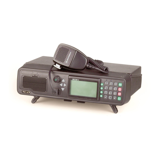
MICOM-3F Front Panel ON/OFF & Volume Control Turns radio on and off and controls the speaker volume Tx Indicator Up/Down Keys Lights when Used to scroll radio is MENU Key Display Internal Speaker...
  • Page 23: Micom-3T Front Panel

    Familiarization with MICOM-3 Radios MICOM-3T Front Panel Tx Indicator Up/Down Keys Lights when MENU Key Used to scroll radio is Display values Not used transmitting Displays the main menu ON/OFF & Volume Control Turns radio on and off ESC Key...
  • Page 24: Micom-3R Front Panel

    MICOM-3F/3T/3R HF-SSB Owner’s Guide MICOM-3R Front Panel ON/OFF & Volume Control MENU Key Displays the Turns radio on and off and controls the main menu speaker volume Tx Indicator ESC Key Up/Down Keys Cancels the Lights when last action radio is...
  • Page 25: Rear Panel (All Models)

    MRC, external modems, Morse key, etc. DC connector 3-pin D-type male connector for connection of DC power source Grounding screw Connection of ground to the radio case GPS antenna Connection to the GPS antenna (for MICOM-3 with the optional GPS receiver) connector...
  • Page 26: Lcd Display Functions

    3.3 (3.3 kHz) in the display shown above) Noise blanker is active Clarifier is active (meaning that you selected a frequency deviating from the nominal channel CLAR frequency) Notch filter is active Note For the MICOM-3R, the squelch and monitor functions also effect the handset.
  • Page 27 Audible Indications The user can configure the MICOM-3 to generate audible tones to indicate events related to the radio operating conditions. The tone volume, low or high, may also be set using the RSS, MRC or by programming from the front panel.
  • Page 28: General Procedures

    MICOM-3F/3T/3R HF-SSB Owner’s Guide General Procedures This section provides general procedures that will help you start using your MICOM-3 radio and get the most of its advanced features. Most of the activities that can be performed by you (selection of operating mode, status display, programming, testing, etc.) are done using the keypad together with the four navigation keys (up, down,...
  • Page 29: Function Keys

    Familiarization with MICOM-3 Radios Function Keys The function keys F1, F2, F3 and F4 appearing next to the display are soft keys used to select options which depend on the current radio mode. The current function of each key is shown in the...
  • Page 30 MICOM-3F/3T/3R HF-SSB Owner’s Guide Alphanumeric Edit Mode When you need to enter an alphanumeric string in a field, or edit a string, you type the desired alphanumeric character on the keypad. A blinking cursor _ indicates the location being edited.
  • Page 31: Using The External (Usb) Keyboard Option (Micom-3F/3R Only)

    Familiarization with MICOM-3 Radios Using the External (USB) Keyboard Option (MICOM-3F/3R only) MICOM-3F and MICOM-3R have a USB connector (see pages 4 and 6) for connecting the optional external keyboard with USB connector. Note When you plug in the keyboard while the radio operates, the LCD displays for a short time DEVICE RM followed by USB KEYBOARD DETECTS.
  • Page 32: The Menu

    MICOM-3F/3T/3R HF-SSB Owner’s Guide The Menu The menu is used to select what you want your radio to do. To display the menu: MICOM-3 1. Press MENU to display the first part of the Menu screen. MENU CHAN You can press the...
  • Page 33 What you can Select Use the following description with Figure 1, which shows the details of the main menu. Additional options are available for a MICOM-3 with the GPS receiver option (see the Using the MICOM-3 GPS Receiver section starting on page 104).
  • Page 34: Basic Operating Instructions

    Automatic Link Establishment (ALE) section, starting on page 34. You can use these instructions to start using your MICOM-3 radio and become familiar with its operation. In most cases, the radio reaches you after being configured for use in your radio net.
  • Page 35: Transmitting And Receiving

    Basic Operating Instructions Transmitting and Receiving • When transmitting, the RF output of the radio must be connected to an Notes antenna installed as explained in the Installation section – page 104 (for maintenance, you may also connect to a dummy load of suitable power rating).
  • Page 36: Using The Channel Mode

    The following sections describe how to use the Channel mode. Selecting the Channel Mode In general, the MICOM-3 automatically enters the Channel mode when turned on, and starts using the last used channel. If not, use the Menu screen to select the Channel mode: this is the first item on the menu you see when you press MENU.
  • Page 37: To Select Channel Mode Options

    To select Channel mode options: Refer to Figure 2 for a concise description of the options available in the Channel mode. Additional options are available for MICOM-3 with the GPS receiver option (see the Using the MICOM-3 GPS Receiver section starting on page 104).
  • Page 38 MICOM-3F/3T/3R HF-SSB Owner’s Guide Note CLAR (F1) and (F2) function keys are not available for TXO (transmit only) channels. MICOM-3 CLAR CLIP - OFF • CLIP (F3) – toggles the clipper on/off. CLIP MICOM-3 CLAR NB - OFF • (F4) – toggles the noise blanker on/off.
  • Page 39: To Choose A Channel

    Basic Operating Instructions MICOM-3 CH 6 F 16,000.00 VP-116 only Vocoder only BAND For duplex and TX only channels PVT# PVT# DGTL Only for ALE Enabled More More More BAND MODE RCLV CALL Note 1 Note 2 CLAR -200 SLOW...
  • Page 40: Using The Frequency Mode

    MICOM-3F/3T/3R HF-SSB Owner’s Guide Note To access the priority channel (available in the Scan mode, that is, when ALE is disabled, provided it has been preprogrammed by the RSS or MRC), press momentarily. MICOM-3 2. To use the displayed channel, press ENTER.
  • Page 41: To Enter The Frequency Mode

    • Transmission: 1.6 to 30 MHz. • The Frequency mode is accessible only if the radio is not locked. Notes • ALE and Frequency modes are mutually exclusive. To enter the frequency mode: MICOM-3 MENU CHAN FREQ 1. Press MENU to display the Menu screen.
  • Page 42 MICOM-3F/3T/3R HF-SSB Owner’s Guide MICOM-3 DPLX SMPX The current frequency type is displayed in the top line, F 14,000.00 DPLX followed by the frequencies in use. 2. If necessary, change the frequency type by pressing the relevant function key: SMPX...
  • Page 43: To Operate The Vfo Function

    Basic Operating Instructions MICOM-3 DPLX SMPX 5. If you are using DPLX frequency type, the frequency T 14,000.00 DPLX displayed first is the Rx frequency. To display the transmission frequency, press DPLX (F2). If you want to use the displayed Tx frequency, press ENTER.
  • Page 44: To Return To The Regular Frequency Mode

    MICOM-3F/3T/3R HF-SSB Owner’s Guide MICOM-3 FRQ-B F 14,000.00 5. Press (F1) to alternate between the two frequencies. <-- --> 6. Press (F2) to copy the frequency of the displayed channel to the alternate channel. 7. You can adjust the frequency of either A or B at any time, using the following methods: •...
  • Page 45: To Select Frequency Mode Options

    The display reflects the options selected. Refer to Figure 3 for a concise description of the options available in the Frequency mode. Additional options are available for MICOM-3 with the GPS receiver option (see the Using the MICOM-3 GPS Receiver section starting on page 104).
  • Page 46 MICOM-3F/3T/3R HF-SSB Owner’s Guide MICOM-3 FREQ SQUELCH ON BAND (F3) toggles the squelch on/off. MICOM-3 FREQ CLAR (F4) accesses the Digital Signal Processing menu, which DSP PARAM includes the following options: CLIP MICOM-3 FREQ • CLAR (F1) – controls the clarifier (off/lower frequency/higher CLAR OFF <--...
  • Page 47: To Store A Frequency In A Channel

    Basic Operating Instructions MICOM-3 FREQ MODE (MORE, F2) – selects the operation mode (SSB, AME or MODE SSB PLT). MICOM-3 FREQ (MORE, F3) – controls the automatic gain control AGC FAST MODE (fast/slow/off). MICOM-3 FREQ BW 2.7 (MORE, F4) – selects the filter bandwidth.
  • Page 48: Using The Scan Mode

    The Scan mode is available only when ALE is turned off using MENU>PROG>RAD>OPT>ALE. In the Scan mode, MICOM-3 scans preprogrammed channels. The channels used in the Scan mode are organized in groups. Up to five scan groups, identified as A to E, may be created using the RSS or MRC, each containing up to 200 channels.
  • Page 49: Using The Bit Mode

    Scan, all the current options will be lost and replaced by the values configured for the various channels. Using the BIT Mode The BIT mode lets you check that the MICOM-3 is OK, and identify any malfunctions. To enter the BIT mode: MICOM-3...
  • Page 50: Locking The Radio

    MICOM-3F/3T/3R HF-SSB Owner’s Guide Locking the Radio You can use the Lock mode to prevent unauthorized persons from accessing the programming and frequency modes. To enter the Lock mode, you need to provide a password. The password consists of six digits.
  • Page 51: Changing The Password

    If you have not yet set a password, use the factory-defined password, 123456. MICOM-3 5. Press O.K. (F1) after you enter the old password. WRONG PSW! If you enter the wrong password, MICOM-3 displays an error message. 6. Enter the new password with the keypad. MICOM-3 PSW SAVED 7. Press O.K.
  • Page 52: Using Automatic Link Establishment (Ale)

    Using Automatic Link Establishment (ALE) The MICOM-3 unit supports the Automatic Link Establishment (ALE) function, a method that enables automatically selecting the best working channel from a group of preprogrammed channels without any user intervention, thereby facilitating communication among HF radio stations and improving the communications quality and reliability.
  • Page 53 Using Automatic Link Establishment (ALE) Identification of a sounding signal sent from a station indicates a high probability of bidirectional communication. The length of the sounding cycles can be set to short or long cycles, depending on propagation conditions. When propagation changes are slow, long intervals of about 1 or 2 hours may be sufficient.
  • Page 54 The bidirectional handshake is an operator-initiated procedure used to exchange LQA scores with other stations without establishing a link. Note The MICOM-3 can also be programmed to automatically initiate the call to the station after finishing the bidirectional handshake (using the BDLK parameter reached under the ALE programming options).
  • Page 55: Selective Calling

    In the following sections, “A,” “B,” “C” or “D” indicates any alphanumeric character other than “@” or “?”. MICOM-3 has the capacity to store and use 100 addresses of up to 15 characters each. MICOM-3 will reject addresses longer than 15 characters, and will notify you with an UFA WRONG message.
  • Page 56 MICOM-3F/3T/3R HF-SSB Owner’s Guide Individual Station Address The individual station address may contain 1, 2, 3, 4, or 5 words. To enable using addresses that are not an integer multiple of 3 characters (for example, an address consisting of 1, 2, 7, 8, 10, …, etc.
  • Page 57 Using Automatic Link Establishment (ALE) Group Addresses The purpose of a group call is to rapidly and efficiently establish contact with multiple non- prearranged (group) stations. To make a group call, a calling ALE station uses a sequence of the actual individual station addresses of the called stations.
  • Page 58 When a radio issues an AllCall, all the stations that are capable of receiving calls receive the AllCall. In the scan mode, if the MICOM-3 station is set to receive AllCalls, it stops scanning when an AllCall is received. If an AllCall channel has been defined, then outgoing AllCalls are performed on that channel.
  • Page 59 For this purpose, MICOM-3 radios offer the MultiNet feature. When the MultiNet feature is enabled, a MICOM-3 radio can operate on multiple nets (up to 20). The operating characteristics then change as follows: •...
  • Page 60 MICOM-3F/3T/3R HF-SSB Owner’s Guide During operation, the MICOM radio scans all the frequencies included in the defined nets: • When the radio receives a call, it responds with the self-address that is programmed in the radio for that net. •...
  • Page 61: Using Ale Functions In The Channel Mode

    (F1) key is displayed even in the Channel mode. The only restriction is that in the Channel mode, MICOM-3 uses only the ALE parameters of net 1. Therefore, if net 1 is not programmed, no ALE functionality is available in the Channel mode, even when the ALE mode is enabled.
  • Page 62: Ale Programming

    MICOM-3F/3T/3R HF-SSB Owner’s Guide ALE Programming ALE supports many features, including: • Various type of calls • Up to 20 nets, each with its own set of members and associated frequencies (channels) • Up to 100 ALE addresses in the directory •...
  • Page 63: Receiving And Transmitting Calls In Ale Mode

    For a description of the link options, see pages 48 to 52. Receiving Calls in ALE Mode When your MICOM-3 receives a call, it displays its type and the source address. MICOM-3 FROM...
  • Page 64: Receiving A Net Call

    MICOM-3F/3T/3R HF-SSB Owner’s Guide Receiving a net call: MICOM-3 FROM NET CALL When your radio receives a net call (i.e., a call addressed to all the stations in your net), the display flashes a net call alert that alternates the words NET CALL with the calling station name.
  • Page 65: Receiving A Sounding Call

    When the radio is in the ALE mode and it receives a sounding call from another station, the calling station name appears in the MICOM-3 display, preceded by the letter S to identify that the call is a S ABCDE sounding call.
  • Page 66: To Select Link Mode Options

    MICOM-3F/3T/3R HF-SSB Owner’s Guide Link State After the radio successfully receives or transmits a call, it is in the link state. MICOM-3 FROM If the call was received from another radio, the display includes the word FROM in the first line, as well as the name of the station which initiated the call (if a message has been received, it is also displayed).
  • Page 67 The LQA (F3) key is displayed only if you established the link in the ALE mode (in the Channel mode, this function is not available, because the call is received/transmitted on the current channel). MICOM-3 CALL MONITOR ON (F4) turns on and off monitoring by means of the speaker.
  • Page 68 MICOM-3F/3T/3R HF-SSB Owner’s Guide MICOM-3 LINK CLAR CLIP - OFF • CLIP (F3) – toggles the clipper on/off. CLIP MICOM-3 LINK CLAR NB - OFF • (F4) – toggles the noise blanker on/off. CLIP MICOM-3 LINK ATTEN - ON ATTN •...
  • Page 69: To Replace The Channel

    Channel replacement is possible only during an individual call in the ALE Notes mode. • Only the initiator of a call can replace the channel in use. To replace the channel: MICOM-3 LINK REPLACE BAND 1. Press MORE to scroll to the second link state menu.
  • Page 70: To Return A Call To A Station Registered In The Stack

    MICOM-3F/3T/3R HF-SSB Owner’s Guide To return a call to a station registered in the stack: 1. Press STAK (F3). 2. Use the UP/DOWN keys to scroll to the required call. 3. Press CALL (F1). 4. Press PAGE (F2) if you want to attach a message when you reply to the call.
  • Page 71: To Disconnect An Incoming Call

    MICOM-3 stores the last called address, so you can simply press the PTT twice in rapid sequence (double pressing) to call again that address. This also applies to AllCall, and therefore after sending AllCall for the first time, you can send it again by double pressing the PTT.
  • Page 72: To Transmit An Individual Call With Multinet Off

    MICOM-3F/3T/3R HF-SSB Owner’s Guide MICOM-3 CALL 2. To change the currently used net, press the UP/DOWN keys, or enter the net number on the keypad, and then press ENTER. Calls to an Individual Station To transmit an individual call with MultiNet OFF: 1.
  • Page 73: To Transmit An Individual Call With Multinet On

    Using Automatic Link Establishment (ALE) MICOM-3 STOP 4. The radio now starts the link set up process. During this 1234 process, you will see TO alternating with the number of the channel on which the set up request is being sent (the channel may change, if the called station does not answer on the first channel(s)).
  • Page 74: To Transmit On A Specific Channel

    MICOM-3F/3T/3R HF-SSB Owner’s Guide Note While the radio is initializing the link, you can press STOP (F1) or to abort the entire process. 6. After the link is established, you will see a LINK message. Now you may press the PTT and start talking.
  • Page 75: To Send A Quick Call

    "most recent" station data exists. To send a quick call: Double-press the PTT of your microphone or handset. The radio automatically tries to contact the last called station. MICOM-3 STOP During this process, you will see TO alternating with the number of 1234...
  • Page 76: To Use Autodial To Send A Call

    MICOM-3F/3T/3R HF-SSB Owner’s Guide Using Autodial The Autodial feature lets you use a single digit to call a preprogrammed address. There are ten programmable Autodial addresses, where each can include a message. See Auto Dial Parameters on page 93 for details on programming the Autodial list.
  • Page 77: To Transmit An Individual Call With A Message

    In the link state, if you are making an individual call, both the receiving and the calling station can send messages to the other station. This is also true for net calls and group calls. To transmit an individual call with a message: MICOM-3 CALL SEND 1.
  • Page 78: To Send A Message During A Call (Link State)

    MICOM-3F/3T/3R HF-SSB Owner’s Guide To send a message during a call (link state): 1. Press PAGE (F2). MICOM-3 LINK 1009 PAGE Note If this function key is not displayed, you cannot send a message in the present mode. 2. Select or edit the desired message as explained on page 58.
  • Page 79: To Select A Special Call Type

    The special call types are reached under a special submenu, designated MULT (see Figure 5 for its organization). To select a special call type: 1. Press CALL (F1). MICOM-3 CALL SEND 1001 The radio displays the last called address. This may be a station PAGE...
  • Page 80: To Send Global Allcall Using The Esc Key

    MICOM-3F/3T/3R HF-SSB Owner’s Guide SELF Self call – call using the station’s own address, generally used for test purposes. Transmitting AIICalls An AllCall is a message which your radio uses to establish a connection with all the other stations simultaneously, and is typically used to broadcast a message or send a distress call. An AllCall can also include a message.
  • Page 81: To Send Global Allcall Using The Call Function

    Using Automatic Link Establishment (ALE) MICOM-3 END CALLING 5. To end the call, press ESC. To send global AllCall using the CALL function: MICOM-3 CALL SEND 1. Press CALL (F1). 1001 PAGE CHAN The radio displays the last called address.
  • Page 82 MICOM-3F/3T/3R HF-SSB Owner’s Guide MICOM-3 5. Press (F4). EDIT:_ Note If you decide to send a Global AllCall, press GLOB (F3). MICOM-3 6. Type the desired character (only one character is accepted). EDIT:5 Note You can press (F1) if you decide to send a global AllCall.
  • Page 83: To Transmit A Net Call

    The radio must be programmed as a MASTER radio in the net (an ALE Programming option) in order to be able to transmit net calls. To transmit a net call: 1. Press CALL (F1). MICOM-3 CALL SEND The radio displays the last called address. 1001 PAGE...
  • Page 84: To Transmit A Group Call

    MICOM-3F/3T/3R HF-SSB Owner’s Guide Transmitting Group Calls Group calls let you call several individual stations in your net (at least 2) at once. Thus, you can use a group call to communicate with a few select stations, while other stations can still communicate at will, using other channels available to your net.
  • Page 85: To Define Or Change A Group

    While the radio is initializing the link, you can press STOP (F1) or to abort the entire process. MICOM-3 LINK When a net call is transmitted, each member in the group 1111 responds to the call and the initiator of the call receives an indication of the response on the display.
  • Page 86 To make an AnyCall, first you must select the address to be used for the call. MICOM-3 will wait for responses for a certain time before entering the link state with all the stations that responded within this interval (the maximum number of stations that are accepted in an AnyCall...
  • Page 87: To Transmit An Anycall

    CALL (F1) to start a call. To transmit an AnyCall: 1. Press CALL (F1). MICOM-3 CALL SEND The radio displays the last called address. 1001 PAGE If you see the address you want (that is, you want to repeat the...
  • Page 88 MICOM-3F/3T/3R HF-SSB Owner’s Guide MICOM-3 • To send a double-selective AnyCall, enter two ENDING:59 <-- characters. 7. Confirm your selection by pressing ENTER (see below examples for the 3 types of addresses). MICOM-3 MICOM-3 MICOM-3 CALL CALL CALL SEND SEND...
  • Page 89: To Transmit A Wildcard Call

    Each station accepting the call answers the calling station in a pseudo-random slot. MICOM-3 will wait for responses for a certain time before entering the link state with all the stations that responded within this interval (the maximum number of stations that are accepted in a wildcard call is 16).
  • Page 90 MICOM-3F/3T/3R HF-SSB Owner’s Guide MICOM-3 CALL SEND WILD PAGE 5. Press WILD (F1) to start. CHAN MICOM-3 WILD 6. Press (F4). Note If you try to send (SEND (F1)) the call without first selecting an address, your attempt is rejected and you see for a few seconds NOT PROG.
  • Page 91: To Send A Self-Call

    Using Automatic Link Establishment (ALE) MICOM-3 END CALLING 14. To end the call, press ESC. Transmitting a Self Call The self-call is a test call addressed to your own address within the currently selected net. Its purpose is to check that your radio set is OK and can transmit calls (to check reception, you can simply listen to other radio sets).
  • Page 92: To Execute A Bidirectional Handshake With An Individual Station

    When the bidirectional handshake procedure is performed with a net, all the stations in the net update their LQA tables. MICOM-3 will wait for responses for a certain time before entering the link state with all the stations that responded within this interval (the maximum number of stations that are accepted in a bidirectional handshake is 16).
  • Page 93: To Execute A Bidirectional Handshake With A Net

    ENTER to confirm your selection. If the station you want to add to the group is not in the directory: MICOM-3 BIDR SAVE • Enter the new station using the keypad. If you make a <--...
  • Page 94: To Manually Initiate Sounding

    MICOM-3F/3T/3R HF-SSB Owner’s Guide MICOM-3 BIDR SEND PAGE 4. Press MULT (F1). CHAN MICOM-3 BIDR 5. Press (F1). Note You cannot change the net number at this stage – the bidirectional handshake is always performed on the currently selected net. To change the net, see page 53.
  • Page 95 Using Automatic Link Establishment (ALE) Using the Inlink Function MICOM-3 When the inlink function is enabled (see instructions in the ALE Options DISC Configuration section starting on page 91), the stations participating in a 1001 PAGE call are automatically notified by a DISC message whenever another participant leaves (disconnects from) the call.
  • Page 96: Using The Programming Mode

    Part II of this manual – Manual Programming. The Programming (PROG) mode is used to program the parameters needed by your radio set: • Language – the language used on the MICOM-3 display. The default language is English, however you also select French or Spanish. •...
  • Page 97 Using the Programming Mode MICOM-3 MENU LOCK PROG LANG LANG Option Option FRNC CONF ESPA ERAS More CHAN PRMT OPTS TUNE NONE More More BAUD DPWR PTBP KBBP TONE ATTN RCLV 0.25 HIGH HIGH More More STOR ERAS FREQ BAND...
  • Page 98: Micom-3F/3T/3R Hf-Ssb Owner's Guide

    MICOM-3F/3T/3R HF-SSB Owner’s Guide MICOM-3 MENU LOCK PROG LANG Option Option FRNC CONF ESPA ERAS More More AUTO STOR ADDR EDIT ERAS More More More ERAS ILNK BDLK PTOT MLQA MxCH AUTO ERAS SAVE SAVE --> EXAL QCAL ALRT WILD...
  • Page 99: Programming The Radio Parameters

    The Radio Programming mode is used to program the following types of parameters: • Channel parameters • General radio parameters • Radio options. The following sections explain the programming procedures. To enter the Radio Programming mode: MICOM-3 MENU CHAN FREQ 1. Press MENU to display the Menu screen.
  • Page 100: Programming Channels

    The CHAN menu provides the following options (see also Figure 6): • GET retrieves a channel already programmed in MICOM-3. Retrieving a channel retrieves all the parameters defined for that channel. You can store these parameters as a new channel using the STOR function, and then edit the parameters as required.
  • Page 101 • PLT – single sideband with pilot signal. • Select the channel Automatic Gain Control mode. MICOM-3 offers two AGC response speeds: SLOW and FAST. You can also turn the AGC OFF completely. • Select the default channel filter bandwidth: •...
  • Page 102: Selecting Radio Parameters

    MICOM-3F/3T/3R HF-SSB Owner’s Guide Selecting Radio Parameters To enter the Radio Parameters programming mode: MICOM-3 RADIO CHAN PROGRAMMING PRMT 1. Enter the Radio Programming menu (page 79). OPTS MICOM-3 RADIO PARAMETERS STOR 2. Press PRMT (F2). ERAS The PRMT option in the Radio Programming menu provides the following options (see also Figure 6): •...
  • Page 103 Programming the Radio Parameters • Select the alternate display time-out, that is, the time after which a keypad sequence is automatically aborted in case no action is taken. In this case, the display returns to the previous screen. The time-out interval can be selected in the range of 1 to 10 seconds. •...
  • Page 104: Setting Radio Options

    TUNE Enables/disables operation with an external antenna tuner. If you are using an external tuner, you must set this option to YES. • Enables/disables the ALE functionality. When the ALE option is disabled, MICOM-3 can use the Scan Mode (see Using the Scan Mode on page 30).
  • Page 105: Ale Programming

    Edit the list of stations not appearing in the directory from which calls have been received. This item is displayed only after such calls have been received, and therefore will not appear when the MICOM-3 is just turned • Directory: configuration of the ALE address list.
  • Page 106: Programming Nets

    MICOM-3F/3T/3R HF-SSB Owner’s Guide • STOR Store the changes made in the ALE programming session. The following sections explain the programming of these features. For detailed instructions, refer to Part II of this manual. • key is used to cancel a change you have made, if not yet confirmed.
  • Page 107 ERAS Erase an entire network from the ALE data base. After preparing a set of parameters, your entries are checked and any errors are reported. If you do not correct the detected errors, MICOM-3 will offer to discard the new set of parameters. Default Values Unless you define different values, each net uses the following factory-defaults: •...
  • Page 108: Setting The Net Options

    MICOM-3F/3T/3R HF-SSB Owner’s Guide Setting the Net Options Use this menu to configure net options. The following sections explain the purpose of the net options. For detailed instructions, refer to Part II of this manual. • SOND Sounding Parameters: define the interval (in minutes) at which automatic sounding is performed (30, 60, 90 or 120 minutes), or define sounding as a manual function.
  • Page 109: Amd Message Configuration

    ALE Programming AMD Message Configuration The AMD option of the ALE Programming menu is used to view, edit, add or erase messages intended for transmission. The characters you can enter in messages using the radio keypad are: A to Z, 0 to 9, space, * and #. See message preparation details on page 59. Messages programmed using a remote PC with a standard keyboard can contain all the ASCII characters the range of 20 (hex) to 5F (hex).
  • Page 110 MICOM-3F/3T/3R HF-SSB Owner’s Guide • MultiNet: enable/disable the scanning of multiple ALE nets. When enabled, this feature lets the radio communicate with stations in nets other than the currently selected net. • Maximum Scan Channels: when MultiNet is enabled, the time needed for scanning MxCH all the nets may be rather long.
  • Page 111: Auto Dial Parameters

    ALE Programming Auto Dial Parameters Auto Dial enables you to set shortcuts for calls to frequently called stations, with or without automatically attaching messages when a station is called: • Used to configure up to 10 autodial codes, numbered AUTO 0 to AUTO 9. AUTO •...
  • Page 112: Using The New Station Address Filter

    To help you add new station addresses to the ALE directory of your radio set in a controlled manner, MICOM-2 has a special ALE address filter. To enable this filter, enable the Auto Address function on menu (this function can also be enabled by means of the RSS).
  • Page 113: Using The Vp-116 Mini Voice Privacy Unit

    The VP-116 Voice Privacy unit provides voice privacy at good voice quality. For information on the VP-116 unit, read the manual supplied with the unit. You can order option G849 that enables the MICOM-3 to support the VP software, so that you can program the VP-116 unit directly from the radio.
  • Page 114: Using The Vp-116 Unit

    MICOM-3F/3T/3R HF-SSB Owner’s Guide 4. Turn the radio off. 5. Disconnect the VP-116 from the 44-pin accessories connector of your MICOM-3. 6. Turn the radio on. Using the VP-116 Unit When operating the radio with the VP-116 unit in the Channel, Frequency or ALE mode, you can choose between the CLR and PVT (private) modes: •...
  • Page 115: Programming The Vp-116 Unit From The Micom-3

    Using the VP-116 Mini Voice Privacy Unit Programming the VP-116 Unit from the MICOM-3 The PROG menu of the MICOM-3 provides access to the following functions: • Programming the VP-116 unit key. • Adjusting the volume provided by the VP-116 unit to match the normal radio volume.
  • Page 116: To Select The Vp-116 Private Mode And The Key To Be Used In This Mode

    MICOM-3F/3T/3R HF-SSB Owner’s Guide MICOM-3 PROG LANG Figure 8. VP Programming Menu More Selecting the VP-116 Mode and Keys VP-116 offers two protection modes: privacy and public key encryption. The keys to be used must be loaded into the VP-116, before starting operations.
  • Page 117: To Respond To A Vp-116 Public Key Call

    Using the VP-116 Mini Voice Privacy Unit When the other unit responds, you will see PVT-P. 3. Press PTT to start talking in the PK mode. To cancel the call, both parties must press ESC. If after 120 seconds there is no response from the other station, or the radio identifies a communication error, the message ERR RESPONSE is displayed.
  • Page 118: Using The Vocoder

    MICOM-3F/3T/3R HF-SSB Owner’s Guide Using the Vocoder Introduction A vocoder option can be ordered for the MICOM-3. The vocoder provides voice privacy at good voice quality, using digital signal processing techniques. The vocoder supports the following protection modes: • Privacy (PVT) mode, compatible with the VP-116 Mini Voice Privacy Unit. The vocoder can store up to 8 private keys for use in this mode.
  • Page 119: To Use The Vocoder In The Channel Mode

    Using the Vocoder To use the vocoder in the Channel mode: MICOM-3 1. Press the F1 key whenever it is necessary to toggle between the F 16,000.00 BAND PVT (Private), DIG, and CLR (Clear) modes. BW3.3K MICOM-3 PVT3 F 16,000.00 BAND BW3.3K...
  • Page 120: Programming The Vocoder

    MICOM-3F/3T/3R HF-SSB Owner’s Guide Programming the Vocoder The PROG menu of the MICOM-3 provides access to the following functions: • Programming the vocoder private (PVT) key. • Display the vocoder hardware and software versions, and the vocoder configuration. • Erasing the stored keys. You should erase the keys after their validity expires, or as a precaution when the radio must be serviced.
  • Page 121: To Select The Vocoder Private Key To Be Used In This Mode

    Using the Vocoder Selecting the Vocoder Mode and Keys Vocoder offers two protection modes: privacy and public key encryption. The keys to be used must be loaded into the vocoder, before starting operations. Selecting the Vocoder Private Key Private reception and transmission are possible only when a valid key is selected. If the selected key is not valid or is not stored in the vocoder, a tone will be heard and the selection is rejected.
  • Page 122: Using The Micom-3 Gps Receiver

    GPS Receiver Functions The GPS receiver is an integral part of the MICOM-3 transceiver and can be used whenever the GPS antenna supplied together with the MICOM-3 transceiver is properly connected and installed. The GPS receiver provides accurate time and navigation data. The navigation data includes the geographical coordinates (position data) and the altitude.
  • Page 123: Gps Antenna

    (e.g., fiberglass). The antenna connects to the GPS connector of the MICOM-3 transceiver through a 5-meter (15 feet) long coaxial cable, which is part of the antenna. This cable carries both DC power for the antenna, and the received GPS signals.
  • Page 124: Operating The Gps Receiver

    To install the GPS antenna: 1. Place the antenna in the selected place, and make sure it attaches well to the surface. 2. Route the cable to the rear side of the MICOM-3 transceiver, and if required, secure the cable at several places.
  • Page 125 GPS, the GPS data can be immediately displayed, and is updated once per second (time is updated once every 5 seconds). Before using the GPS receiver, turn the MICOM-3 transceiver on and let it operate for at least 15 minutes.
  • Page 126: Operating Instructions

    You can use the ALE AMD service to: 1. Send your position to any another destination (including one-to-many). 2. Request the position of another MICOM-3 transceiver equipped with the optional GPS receiver. You can make this type of request only when you call an individual station: •...
  • Page 127: To Send Your Position Report To Other Station(S)

    You should see the GPS receiver type. • If you see UNKNOWN, turn the MICOM-3 transceiver off and after a few minutes turn it back on. If the problem persists, the GPS receiver must be serviced. •...
  • Page 128: Installation

    MICOM-3F/3T/3R HF-SSB Owner’s Guide Installation General This section describes the installation of the radio in a mobile or fixed station configuration. The following paragraphs contain general installation procedures for both types of configuration. Government Regulations Read carefully the Licensing and Safety Information given in the front matter of this manual. Be sure that all your radio operations comply with these guidelines.
  • Page 129: Base Station Installation

    Installation Base Station Installation In fixed station installation, an AC power supply is used instead of the 12 V battery. It is possible to connect a backup battery to the battery terminals on the power supply. One power supply model is available, FPN5590, for 110/220 V AC, 50/60 Hz.
  • Page 130: Micom-3R Installation

    MICOM-3F/3T/3R HF-SSB Owner’s Guide MICOM-3R Installation Figure 13 illustrates the installation procedure for the MICOM-3R. Trunk Compartment Outside the Car Antenna Antenna Cable Vehicle Frame Ferrite Ground Installation 7.5A Microphone Antenna Connector Green Red Black Battery Engine Passenger Compartment Compartment Figure 13.
  • Page 131: Micom-3F Installation

    MICOM-3F Installation The procedure shown above for the MICOM-3R is also used to install the MICOM-3F. MICOM-3T Installation For MICOM-3T, only the control head, the speaker, and the microphone are installed in the passenger compartment of the vehicle.
  • Page 132 Figure 16. Typical MICOM-3T Installation Within Vehicle The MICOM-3T model requires the connection of two cables across the length of the vehicle because the radio transceiver is located in the trunk. If the battery is located in the rear section of the vehicle, the power cable extends to the battery location.
  • Page 133: Installation Procedures

    Installation Installation Procedures Follow these procedures to install the radio in the desired location. If the accessory mounting tray is not used, ignore the steps pertaining to it. Mobile Mounting Kit Step 1. Mount the accessory mounting tray in the desired location. Use the tray as a template if holes must be drilled.
  • Page 134 MICOM-3F/3T/3R HF-SSB Owner’s Guide Step 2. Thread the ends of the red and green wires from the power connector through the two fuse holder caps. Cut apart the two fuse clips and solder or crimp them to the wires. Step 3.
  • Page 135: Microphone Clip

    Drill 1/8” Holes in Dashboard Figure 20. Microphone Clip Mounting the MICOM-3T Control Head 1. Using the trunnion mounting plate as a template, mark the position of the holes on the mounting surface. 2. Secure the trunnion mounting bracket to the surface with the four (10-16 × 1”) self drilling screws, or drill a 6 mm φ...
  • Page 136 Insert a small, flat-blade screwdriver in the slotted area on the right hand-side panel of the radio and press the screwdriver towards you, to release the control head. Figure 22. Opening the MICOM-3F Control Head Step 2. Disconnect the internal speaker from the board.
  • Page 137: Operational Checks

    Step 3. Return the top cover to its original position by applying pressure on both sides of the cover. Observe that the seal is correctly located. MICOM-3T Final Connections Ensure that the radio is off before making these connections. Warning 1.
  • Page 138: Connectors

    Connectors MICOM-3F/3T Microphone Connector The microphone connector is located on the lower part of the radio front panel. Table 3 lists the functions of the microphone connector pins. Table 3. MICOM-3F/3T Microphone Connector, Pin Functions Designation Description SWA+ Power output to the microphone...
  • Page 139: Antenna Connector J2

    Installation Antenna Connector J2 The N type antenna connector is located on the rear panel of the transceiver. In transmit mode, it is used to feed the antenna with the transmit power; and in receive mode it is used to deliver the received signal from the antenna to the radio.
  • Page 140 MICOM-3F/3T/3R HF-SSB Owner’s Guide Table 5. Accessories Connector Pin Functions (Cont’d) Designation Description EXT ALARM External alarm output (open collector, pulled to ground when external alarm is activated Flash programming voltage, input to BDM DSC/KW_ALC BDM – Data serial clock/kW amplifier ALC...
  • Page 141 Installation DC Power Connector The DC power connector located on the rear panel of the radio is used to provide power to the radio. Table 6 lists the functions of the DC connector pins. Table 6. DC Power Connector, Pin Functions Designation Description TX Power...
  • Page 142: Maintenance

    MICOM-3F/3T/3R HF-SSB Owner’s Guide Maintenance Introduction This section provides maintenance information for the user of the MICOM-3 radio. By carrying out the installation procedures correctly and following the maintenance instructions properly, you ensure continuous operation of your radio set. When an internal problem appears or is suspected, the MICOM-3 internal BITE (built-in test equipment) will assist you in locating the source of this possible problem to inform the service representative accordingly.
  • Page 143: Using Bit

    Maintenance Using BIT Every time the radio is turned on, a self-test procedure is performed. If an internal malfunction is found, an error message will be displayed. Please contact your service representative and report the malfunction or error indicated by the BIT function. Table 7 lists the error messages that may be generated by the BIT function.
  • Page 144 MICOM-3F/3T/3R HF-SSB Owner’s Guide Table 7. Error Messages (Cont’d) Error Code Meaning Probable Cause Preselector range 3 LORD board problem Preselector range 4 LORD board problem Preselector range 5 LORD board problem Preselector range 6 LORD board problem Preselector range 7...
  • Page 145: Troubleshooting

    Maintenance Troubleshooting In case a problem or malfunction occurs, identify the closest description appearing in Table 8 and then perform the listed corrective actions. Table 8. Troubleshooting Chart Problem Corrective Actions Blank display CHECK • DC power cable is connected properly to the radio and battery. •...
  • Page 146 MICOM-3F/3T/3R HF-SSB Owner’s Guide In case a failure occurs during operation, the radio displays a fault message. Refer to Table 9 and perform the corrective actions listed for the corresponding message. Table 9. Fault Messages Message Corrective Actions NO CLOCK CHECK •...
  • Page 147: Service

    Maintenance Service Proper repair and maintenance procedures will assure efficient operation and long life for this product. A maintenance agreement will provide expert service to keep this and all other communication equipment in perfect operating condition. For a contract service agreement, please contact your nearest service representative, or sales representative at MOBAT USA, 1720 West Paul Dirac Drive, Tallahassee 32310 FL, USA (support@mobatUSA.com).
  • Page 148: Appendix A Micomtrooper 3 5-50 Watt Hf-Ssb Backpack Transceiver

    Appendix A micomTrooper 3 5-50 Watt HF-SSB Backpack Transceiver Introduction Scope This Appendix covers the installation and operation of the micomTrooper 3, the 5-to-50W backpack transceiver version of the MICOM-3 transceivers. Whip Antenna micomTrooper Figure 23. micomTrooper 3 Antenna Transceiver...
  • Page 149: Purpose And Use

    Appendix A micomTrooper 3 5-50 Watt HF-SSB Backpack Transceiver micomTrooper 3 is part of the MICOM-3 family of HF-SSB radio sets; it has compatible characteristics and uses the same operating procedures as other MICOM-3 transceivers. Therefore, this manual covers only procedures specific to micomTrooper 3; the other procedures, which are common to the whole MICOM-3 product line, are described in the previous sections.
  • Page 150: Fast And Simple Radio Link Establishing

    Main micomTrooper 3 Operational Features This section presents a concise list of the main operational features of the micomTrooper 3 transceiver. For a complete description of all the capabilities and features of MICOM transceivers, see the Performance Specifications section. Fast and simple radio link establishing: •...
  • Page 151: Part Of A Proven Family Of Radio Products

    Part of a proven family of radio products: • micomTrooper 3 is a member of the family of MICOM radio transceivers for fixed base stations, mobile vehicle-mounted and hand-carried units serving the long-range wireless communication needs of hundreds of organizations worldwide.
  • Page 152: Preparing The Micomtrooper 3 For Operation

    MICOM-3F/3T/3R HF-SSB Owner’s Guide Preparing the micomTrooper 3 for Operation Scope This Section provides instructions for preparing the micomTrooper 3 for backpack operation. The information presented in this Section includes: • Unpacking • Familiarization with main equipment components • Preparation for backpack operation Refer to page 141 for instructions on how to adapt the backpack transceiver to static operation with dipole or other long-wire antennas.
  • Page 153: Backpack Carrying Harness

    Appendix A micomTrooper 3 5-50 Watt HF-SSB Backpack Transceiver Familiarization with micomTrooper 3 Before continuing, review Figure 23, which shows a micomTrooper 3 transceiver installed in its harness. Backpack Carrying Harness Figure 24 shows a general view of a typical backpack carrying harness. The harness has a frame that supports the transceiver and also holds the battery.
  • Page 154 MICOM-3F/3T/3R HF-SSB Owner’s Guide Protection Flap (Open) Harness Frame Retaining Straps Power Cable to Transceiver Battery Frame Battery Holder Battery Cover Bottom Flap (Open) Battery Battery Clamps (2 places) Figure 25. Typical Backpack Carrying Harness, Open View micomTrooper 3 Transceiver Figure 26 shows a general view of the micomTrooper 3 transceiver, and its connectors.
  • Page 155: Outline Of Preparation Procedures

    Appendix A micomTrooper 3 5-50 Watt HF-SSB Backpack Transceiver Preparing micomTrooper 3 for Backpack Operation To prepare the micomTrooper 3 for static operation, refer to page 141. Outline of Preparation Procedures The preparation of a micomTrooper 3 transceiver for operation includes: 1.
  • Page 156 MICOM-3F/3T/3R HF-SSB Owner’s Guide 6. Fasten the transceiver to the carrying harness with the two retaining straps. Installation of micomTrooper 3 Battery Before starting, make sure that the transceiver is off by turning the volume control fully counterclockwise beyond the detent (you should hear a click).
  • Page 157: Installation Of Whip Antenna

    Appendix A micomTrooper 3 5-50 Watt HF-SSB Backpack Transceiver Installation of Whip Antenna 1. Visually inspect the whip mount connector (located on the ATU) for dirt or damage, and the threadings of the antenna base, and of the whip. Thoroughly clean dust and dirt if necessary.
  • Page 158: Operating Instructions

    MICOM-3F/3T/3R HF-SSB Owner’s Guide Wearing the Backpack Carrying Harness To wear the backpack: 1. Put harness on your back by inserting arms through shoulder straps. Protection Flap Shoulder (Closed) Straps 2. Tighten shoulder straps. Breast 3. Buckle waist straps to belt and Strap adjust to size.
  • Page 159: Preparing Micomtrooper 3 For Static Operation

    Appendix A micomTrooper 3 5-50 Watt HF-SSB Backpack Transceiver Preparing micomTrooper 3 for Static Operation For static operation, the micomTrooper 3 is normally used with a dipole or long-wire antenna. This antenna must be directly connected to the transceiver RF connector. Therefore, first it is necessary to disconnect the connection between the transceiver and ATU, using the instructions presented below.
  • Page 160: Using The Micomtrooper 3 Battery Charger, Fln9541

    MICOM-3F/3T/3R HF-SSB Owner’s Guide Using the micomTrooper 3 Battery Charger, FLN9541 Purpose and Use FLN9541 is an AC-powered battery charger designed to charge 16V, 12Ah Lithium Ion rechargeable batteries of the type used by micomTrooper 3 (ML1416-L). FLN9541 is simple to operate and does not require operator attendance during operation. Yet it provides advanced features, such as fully automatic charging and automatic turn-off after battery charging is completed.
  • Page 161 Appendix A micomTrooper 3 5-50 Watt HF-SSB Backpack Transceiver Note If a power source failure occurs while the battery is being charged, the FINISH CHARGE starts flashing, and an alarm tone is heard. To resume charging after power returns, press again the red CHARGE pushbutton. 7.
  • Page 162: List Of Procedures

    MICOM-3F/3T/3R HF-SSB Owner’s Guide List of Procedures This section presents a list of the main activities explained in this manual and a reference to the location of the procedure in the manual. What you want to do … Go to page …...
  • Page 163 To enter the ALE Programming mode: ................87 To edit the received addresses and add addresses to the ALE directory:......94 To connect the VP-116 to your MICOM-3: ................ 95 To disconnect the VP-116 from your MICOM-3: ..............95 To use the VP-116 unit in the Channel mode: ..............96...
  • Page 164 MICOM-3F/3T/3R HF-SSB Owner’s Guide What you want to do … Go to page … To use the VP-116 unit in the ALE mode: ................96 To access the VP-116 unit programming menu:..............97 To select the VP-116 Private mode and the key to be used in this mode: ......98 To switch to the VP-116 Public Key mode:.................

Table of Contents

Save PDF