Table of Contents
Advertisement
125W HF-SSB Rack-Mount/Desktop
Continuous Duty Transceivers
Table of Contents
Introduction................................................................................................................... 2
Description .................................................................................................................... 2
General..................................................................................................................... 2
Equipment Versions .................................................................................................. 3
Main Features ........................................................................................................... 3
Major Accessories ..................................................................................................... 4
Performance Specifications ............................................................................................ 5
Main Technical Characteristics .................................................................................. 5
Accessories Connectors ............................................................................................. 7
Ordering Options...................................................................................................... 8
Familiarization with Equipment...................................................................................... 9
Front Panels .............................................................................................................. 9
RM125/RM125R Rear Panels .................................................................................. 10
RM125/RM125R Installation ........................................................................................ 12
Installation Planning Guidelines............................................................................... 12
Preparations for Installation ..................................................................................... 14
Installation Procedure - Basic Radio ........................................................................ 14
Installation Procedure - Radio with PPS Option ...................................................... 16
RM125/RM125R Operation......................................................................................... 18
General................................................................................................................... 18
Preparations for Operation...................................................................................... 18
Operating Instructions ............................................................................................. 18
RM1200 1 kW Power Amplifier Option ....................................................................... 19
1 kW System Description ........................................................................................ 19
Functional Description ............................................................................................ 20
RM1200 Main Technical Characteristics.................................................................. 22
Familiarization with RM1200 Equipment................................................................. 24
RM1200 Equipment Installation .............................................................................. 30
Preparations for Installation ..................................................................................... 31
Installation Procedure ............................................................................................. 32
RM1200 Operation................................................................................................. 34
6888882V02
RM125/RM125R
Owner's Guide
1
Advertisement
Table of Contents

Related Manuals for Micom RM125


Summary of Contents for Micom RM125
-
Page 1: Table Of Contents
Accessories Connectors ..................... 7 Ordering Options...................... 8 Familiarization with Equipment..................9 Front Panels ......................9 RM125/RM125R Rear Panels .................. 10 RM125/RM125R Installation ..................12 Installation Planning Guidelines................12 Preparations for Installation ..................14 Installation Procedure – Basic Radio ................ 14 Installation Procedure –... -
Page 2: Introduction
United States of America as well as in other countries. As a backup, RM125/RM125R can also use 13.8 V DC power from an external lead-gel or lead-acid battery, which is automatically charged by the internal AC power supply. When an external battery is connected, the RM125/RM125R can continue operating on battery power during AC mains failure or in case the AC power is switched off. -
Page 3: Equipment Versions
Two main options further enhance the range of applications for the RM125 and RM125R: • MICOM RM1200 Linear High-Power RF Amplifier, FLN3175. This compact amplifier, which covers the full transmit range of the RM125/RM125R, 1.60 to 30 MHz range, offers significantly higher transmit power (1 kW PEP and average), and thus enable improved communications under bad propagation conditions and/or strong interference. -
Page 4: Major Accessories
AMD (Automatic Message Display) for free and pre-set text messages. A proven family of radio products • RM125 and RM125R are members of the MICOM transceiver family – fixed and mobile stations – covering the long-range wireless communication needs of thousands of organizations worldwide. -
Page 5: Performance Specifications
Performance Specifications Main Technical Characteristics This section presents the main technical characteristics of the RM125 and RM125R. For a listing of the additional performance specifications, refer to the “Owner’s Guide, MICOM-3E/3T/3R HF-SSB Transceivers”, Publication 6886867J01, and to the applicable MICOM-3 Supplements that cover the optional features available on your radio set. - Page 6 432.5 MICOM RM-125 MICOM-3 MENU A LA RM 482.5 REMOTE CONTROL PPS-CONT TX OUT RX OUT TX IN RX IN ACC-J1 ACC-J4 ACC-J2 ACC-J3 13.8V RF OUT AMP-CONT 110/220V AC Power Cable 583.1 Figure 2. RM125/RM125R Dimensions 6888882V02...
-
Page 7: Accessories Connectors
PTT and CW control lines, audio and baseband lines for external equipment, auxiliary power output, serial RS-232 asynchronous data interfaces, and additional dedicated handshaking and control lines. The functions supported by the serial data interfaces are determined by the RM125/RM125R software. Table 1. 25-Pin Accessories Connector, Pin Functions Designation... -
Page 8: Ordering Options
Interface cable for MICOM link unit Interface for Pre/Post-Selector (PPS) for co-site and split-site applications G420 2-wire remote control head G156 Interface cable kit for MICOM RM1200 1 kW linear amplifier FLN3175 MICOM RM1200 1 kW (PEP and average) continuous duty linear amplifier unit 6888882V02... -
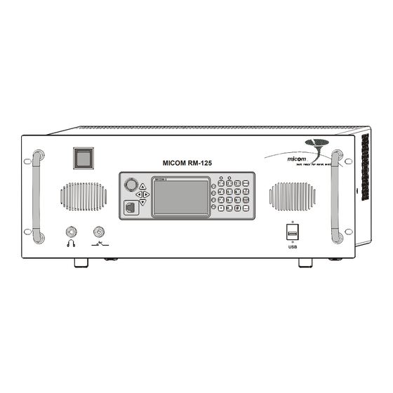
Page 9: Familiarization With Equipment
Familiarization with Equipment Front Panels The front panels of the RM125 and RM125R include a standard MICOM-3 control panel and the additional items identified in Figure 3, respectively Figure 4. For a description of the MICOM-3 control panel, refer to the “Owner’s Guide, MICOM-3E/3T/3R HF-SSB Transceivers”, Publication 6886867J01. -
Page 10: Rm125/Rm125R Rear Panels
RM125/RM125R Rear Panels Figure 5 shows the rear panel of the RM125 and RM125R. The functions of the various items are explained in Table 2. PPS-CONT TX OUT RX OUT REMOTE CONTROL TX IN RX IN ACC-J1 ACC-J4 ACC-J2 ACC-J3 13.8V... - Page 11 Table 2. RM125/RM125R Rear Panel Items (Cont.) Item Description Function TX IN Connector BNC RF input connector, for connection of filtered RF transmit signal from the optional Pre/Post-Selector (PPS) REMOTE CONTROL Connection of 2-wire line to optional 2-wire control head...
-
Page 12: Rm125/Rm125R Installation
AC Power Requirements The RM125/RM125R requires AC power at a nominal voltage of 110 or 220 VAC, 50/60 Hz. The RM125/RM125R will automatically select the appropriate voltage range. The maximum AC power consumption during high-power transmission (excluding the charging of an external battery), is 500W. - Page 13 Cooling RM125/RM125R units are cooled by internal fans. Air is taken in through the front panel vent, and discharged toward the rear. Therefore, make sure that sufficient free space is available around the equipment to enable free air flow.
-
Page 14: Preparations For Installation
IS-B50LN-C0 by PolyPhaser Corp. (also available from Mobat, as Cat. No. 2072-09128-00). Preparations for Installation Before starting the installation of a new RM125/RM125R, review the installation plan and make the following checks: 1. Identify the prescribed location of the equipment in the rack or cabinet. - Page 15 Caution is turned on and powered from AC. 1. Before starting, make sure that the AC power switch on the RM125/RM125R front panel is set to the OFF (down) position. 2. Refer to Figure 6 or Figure 7, as appropriate and start by making the connection to the negative (–) BAT terminal of the RM125/RM125R.
-
Page 16: Installation Procedure - Radio With Pps Option
RM125/RM125R with option G65 and the PPS are shown in Figure 8. When the G65 option is installed, the PPS is controlled by the RM125/RM125R through serial and parallel ports and is automatically inserted by the RM125/RM125R in the signal path in accordance with the operating mode: •... - Page 17 3. Connect a grounding strap from the RM125/RM125R grounding screw to the prescribed cabinet’s grounding bar. 4. Set the power switches on the RM125/RM125R and PPS front panels to OFF (down position). 5. Connect the PPS AC power cable to the prescribed outlet on the power distribution box of the cabinet.
-
Page 18: Rm125/Rm125R Operation
MICOM-3 Supplements that cover optional features. Preparations for Operation 1. Set the REMOTE CONTROL switch on the rear panel of the RM125/RM125R to the OFF (down) position. 2. For the RM125R, set the internal speaker switch to ON (up). -
Page 19: Rm1200 1 Kw Power Amplifier Option
The RM1200 1 kW power amplifier option, FLN3175, which uses the RM125/RM125R as an exciter, expands the MICOM-3 product line by offering higher transmit power (up to 1 kW, PEP and average), and thus longer reach and improved communications under bad propagation conditions and/or strong interference. -
Page 20: Functional Description
The 1 kW amplifier requires a nominal drive power of approx. 40W. When operating the 1 kW amplifier with the RM125/RM125R as driver, the input power is automatically adjusted by an automatic level control to achieve optimal operating conditions for the amplifier. - Page 21 1 kW Amplifier Overheating Protection Special circuits protect the 1 kW amplifier against overheating. If the temperature is too high to enable full-power operation, the output power is automatically halved, until the temperature returns to normal. However, if the temperature exceeds the maximum allowed limit and damage may be caused, the protection circuits are activated and bypass the amplifier.
-
Page 22: Rm1200 Main Technical Characteristics
(control program contained in 1 kW amplifier) • Control and status port for interfacing to the RM125/RM125R as driver Number of system units • 1 kW RF linear power amplifier • AC-powered PS unit, Lambda... - Page 23 Load mismatch • Full transmit power for VSWR up to 1.5:1 • Reduced transmit power for higher VSWR (50% down at VSWR of 4:1) • Full protection against short/open circuit Overheating protection • Reduced transmit power for high temperature • Bypass in case of excessive temperature Operating voltage 45 to 48 VDC from PS unit Power requirements...
-
Page 24: Familiarization With Rm1200 Equipment
Familiarization with RM1200 Equipment 1 kW PA Front Panel Figure 9 identifies the items located on the front panel of the 1 kW amplifier, and Table 3 explains their functions. RM-1200 FAULT BYPASS 1000HF SSB - AMPLIFIER DISPLAY MODE Figure 9. 1 kW PA Front Panel Table 3. - Page 25 1 kW PA LCD Functions The LCD is used to display information on the operational conditions of the 1 kW amplifier, and status information. The LCD comprises 2 rows, and therefore it is necessary to split the information on four different display pages of 2 rows each. The first row of each page always presents two items: •...
- Page 26 RF IN OVERLOAD Excessive drive power supplied to the RF When using the amplifier with a IN input. driver other than RM125/RM125R, check the maximum transmit power 1 kW amplifier is in the bypass mode of the driver unit. and will not transmit until the condition...
- Page 27 Item Description Function RF IN Connector N-type connector for RF connection to the RM125/RM125R: • In the receive or bypass mode, serves as output for receive signals • In the transmit mode, serves as input for RF drive signals +48VDC connector 7-pin circular connector for connection to DC power source...
- Page 28 PS Front Panel Figure 12 identifies the items located on the front panel of the PS unit, and Table 7 explains their functions. OUT 1 OUT 2 AC ON Figure 11. PS Front Panel Table 7. PS Front Panel Items Item Description Function ON/OFF switch...
- Page 29 PS Rear Panel Figure 12 identifies the items located on the front panel of the PS unit, and Table 8 explains their functions. AC INPUT DC OUTPUT 110-230VAC/ 47~63Hz OUT 1 OUT 2 Figure 12. PS Rear Panel Table 8. PS Rear Panel Items Item Description Function OUT 1 +V, -V...
-
Page 30: Rm1200 Equipment Installation
Installation Planning Guidelines section, starting on page 12. Grounding Failure to provide proper grounding to each system unit (RM125/RM125R, 1 kW PA and PS unit, and to the optional PPS) and to the rack in which these units are installed will degrade system operation and cause RF voltage to be present on the equipment chassis. -
Page 31: Preparations For Installation
Cooling RM1200 units, as well as the RM125/RM125R, are cooled by internal fans. Air is taken in through the front panel vents, and discharged toward the rear. Therefore, make sure that sufficient free space is available around the equipment to enable free air flow. -
Page 32: Installation Procedure
Caution PS unit is already turned on. 5. Connect cables to the RM125/RM125R unit as explained in the Installation Procedure – Basic Radio section, starting on page 14, including the relevant DC power connections. The only difference is that the RM125/RM125R RF OUT connector must be connected to the RF IN connector of the 1 kW amplifier. - Page 33 RM125 (Exciter) PPS-CONT TX OUT RX OUT REMOTE CONTROL TX IN RX IN ACC-J1 ACC-J4 ACC-J2 ACC-J3 13.8V RF OUT 110/220V AMP-CONT Control To AC Cable Source To Antenna (via Coaxial Protector) RM1200 (PA) EXCITER CONTROL MONITOR RF Out +48VDC...
-
Page 34: Rm1200 Operation
Publication 6886867J01, and the applicable MICOM-3 Supplements that cover optional features. Preparations for Operation 1. Set the REMOTE CONTROL switch on the rear panel of the RM125/RM125R to the OFF (down) position. 2. For the RM125R, set the internal speaker switch to ON (up). - Page 35 LCD). Service the 1 kW amplifier. However, you can still transmit and receive using the RM125/RM125R by selecting NONE on the PROG>RAD>OPTS>ACC menu. If the BYPASS indicator lights, make sure to select AMP on the RM125/RM125R PROG>RAD>OPTS>ACC menu...
- Page 36 In this case, take the steps described in Item 1 above. Equipment Turn-Off 1. Turn the RM125/RM125R off: turn the front panel ON/OFF switch and volume control fully counterclockwise, beyond the detent position. Now set its AC power switch to OFF. Note At this stage, the 1 kW amplifier is also turned off.
Need help?
Do you have a question about the RM125 and is the answer not in the manual?
Questions and answers