Table of Contents
Advertisement
Safety Precaution For Service Manual ........................................................................................................... 2
Voltage Selection ..................................................................................................................................................... 2
Specifications .............................................................................................................................................................. 3
Names Of Parts ........................................................................................................................................................... 4
Operation Manual ...................................................................................................................................................... 6
Disassembly .................................................................................................................................................................. 7
Removing And Reinstalling The Main Parts ..................................................................................................... 9
Adjustment ................................................................................................................................................................. 10
Notes On Schematic Diagram .............................................................................................................................. 12
Block Diagram ........................................................................................................................................................... 13
Schematic Diagram / Wiring Side Of P.w.board .............................................................................................. 16
Voltage ........................................................................................................................................................................ 32
Waveforms Of Cd Circuit ...................................................................................................................................... 33
Troubleshooting (Cd Section) ........................................................................................................................... 34
Function Table Of Ic ................................................................................................................................................ 39
Fl Display ...................................................................................................................................................................... 46
Parts Guide/EXPLODED VIEW
SERVICE MANUAL
CONTENTS
SHARP CORPORATION
– 1 –
CD-C831W
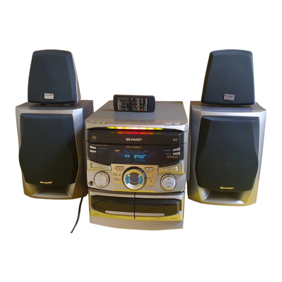
CD-C831W mini component system consisting of CD-C831W
(Main unit), CP-C831 (Front speaker) and GBOXS0025AWM1
• In the interests of user-safety the set should be restored to its
original condition and only parts identical to those specified be
used.
This document has been published to be used
for after sales service only.
The contents are subject to change without notice.
CD-C831W
No. S5934CDC831W/
Page
Advertisement
Table of Contents

Subscribe to Our Youtube Channel
Related Manuals for Sharp CD-C831W


Summary of Contents for Sharp CD-C831W
- Page 1 CD-C831W SERVICE MANUAL No. S5934CDC831W/ CD-C831W CD-C831W mini component system consisting of CD-C831W (Main unit), CP-C831 (Front speaker) and GBOXS0025AWM1 (Surround speaker). • In the interests of user-safety the set should be restored to its original condition and only parts identical to those specified be used.
-
Page 2: Safety Precaution For Service Manual
CD-C831W SAFETY PRECAUTION FOR SERVICE MANUAL WARNINGS THE AEL (ACCESSIBLE EMISSION LEVEL) OF THE LASER POWER OUTPUT IS LESS THAN CLASS 1 BUT THE LASER COMPONENT IS CAPABLE OF EMITTING RADIATION EXCEEDING THE LIMIT FOR CLASS 1. THEREFORE IT IS IMPORTANT THAT THE FOLLOWING PRECAUTIONS ARE OBSERVED DURING SERVICING TO PROTECT YOUR EYES AGAINST EXPOSURE TO THE LASER BEAM. -
Page 3: Specifications
CD-C831W FOR A COMPLETE DESCRIPTION OF THE OPERATION OF THIS UNIT, PLEASE REFER TO THE OPERATION MANUAL. SPECIFICATIONS CD-C831W General Cassette deck section Type: Compact cassette tape Power source: AC 110/127/220/230-240 V, Frequency response: 50 - 14,000 Hz (Normal tape) -
Page 4: Names Of Parts
CD-C831W NAMES OF PARTS CD-C831W Front Panel 1. Disc Number Selector Buttons 2. Disc Tray 3. Multi Indicator 4. Disc Skip Button 5. Open/Close Button 6. Extra Bass Indicator 7. FM Stereo Mode Indicator 8. FM Stereo Indicator 9. (CD) Repeat Indicator 10. - Page 5 CD-C831W Rear Panel 1. AC Voltage Selector 2. AC Power Input Socket 3. AM Aerial Terminal 4. Aerial Earth Terminal 5. FM 75 Ohms Aerial Socket 6. Video/Auxiliary (Audio Signal) Input Sockets 7. Span Selector Switch 8. Surround Speaker Terminals 9.
-
Page 6: Operation Manual
CD-C831W OPERATION MANUAL – 6 –... -
Page 7: Disassembly
CD-C831W DISASSEMBLY CD-C831W Caution on Disassembly Follow the below-mentioned notes when disassembling Top Cabinet the unit and reassembling it, to keep it safe and ensure (A1) x2 excellent performance: ø3x12mm 1. Take cassette tape and compact disc out of the unit. - Page 8 CD-C831W (E1) x2 (N1) x1 ø3x10mm (F2) x2 (F1) x1 ø3 x10mm ø3x10mm Front Panel (F5) x1 CD Servo PWB (F4) x1 (N2) x2 (F2) x2 (F3)x1 (E2) x1 (G2) x1 (G3) x1 (N2) x2 CD Player Unit (E1) x1 ø3x10mm...
-
Page 9: Removing And Reinstalling The Main Parts
CD-C831W (A3)x2 CP-C831 ø3x10mm STEP REMOVAL PROCEDURE FIGURE Tweeter (A3)x4 (A2)x2 Front Speaker 1. Front Panel .... (A1) x1 ø4x12mm 2. Tip ......(A2) x2 3. Screw ..... (A3) x6 Note: The Surround speakers can be easily disassembled. Therefore the disassembling method is not described. -
Page 10: Adjustment
CD-C831W ADJUSTMENT MECHANISM SECTION • FM • Driving Force Check Notes: 1: Description of the "FM IF Adjustment" is not carried on this Torque Meter Specified Value Manual. It is because the IF coil in the FM front end section... -
Page 11: Test Mode
CD-C831W TEST MODE • Setting the test mode Any one of test mode can be set by pressing several keys as follows. <REC. PAUSE> + <DISC. SKIP> + <POWER> TEST: CD operation test • TEST mode Function — CD test mode Setting of TEST mode Indication of CD TST mode (Fig. -
Page 12: Notes On Schematic Diagram
CD-C831W NOTES ON SCHEMATIC DIAGRAM • The indicated voltage in each section is the one measured • Resistor: by Digital Multimeter between such a section and the chas- To differentiate the units of resistors, such symbol as K and sis with no signal given. -
Page 13: Block Diagram
CD-C831W TO MAIN SECTION 9 8 7 6 5 4 3 2 1 TO MAIN SECTION (TO IC601) +7.3V (B1) CNP11 1 2 3 4 5 6 9 8 7 6 5 4 3 2 1 REGULATOR +4.3V 33 38 39 46... -
Page 14: Voltage
CD-C831W SO301 ANTENNA TERMINAL FM IF FE301 CF302 AM IF 75 ohms FM FRONT END T351 CF352 SWM3 FM IF IN FOOL PROOF SWM4 F.A.S FM/AM SOLM1 IC303 SOLENOID VR351 LA1832 FM MUTE LEVEL SWM5 FM/AM IF MPX. AM OSC... - Page 15 CD-C831W SWM3 L PROOF FL701 SWM4 F.A.S DISPLAY SOLM1 OLENOID Q702 SWM5 1 2 3 4 37 38 39 Q703 TAPE MOTOR Q705 Q706 Q707 SW601 SPAN SELECTOR D701 ~D704 IC701 IX0281AW OR IX0310AW SYSTEM CONTROL FM/AM SWITCHING MICROCOMPUTER IC704...
- Page 16 CD-C831W RECORD SIGNAL FM SIGNAL PLAYBACK SIGNAL CNS11 R-CH A_GND L-CH CD_GND R639 C601 4.7/50 +12V R607 1.5K R608 C605 R605 1.5K R606 4.7/50 R603 1.5K R604 R602 C603 R601 1.5K 4.7/50 C611 0.033 C612 C615 C613 C614 0.22 0.22...
- Page 17 CD-C831W CD SIGNAL R633 L-CH R631 C631 JK601 390P VIDEO C602 R634 C632 R632 4.7/50 R642 1.5K 390P R-CH C606 1.5K C654 4.7/50 4.7/50 1.5K R640 47K D601 1.5K 1SS133 D602 C612 0.033 C604 1SS133 Q650 4.7/50 R626 2.2K R641 C614 0.22...
- Page 18 CD-C831W IC901 STK407-040B POWER AMP. (2Ch) C915 C923 120P R912 R921 100(1/4W) C916 Fusible C911 R917 R918 100/50 R916 C912 100/50 R913 C917 100 (1/4W) Fusible 47/50 R926 0.1 (1W) D903 D906 1SS133 1SS133 C921 C920 0.022 0.022 R931 C901...
- Page 19 CD-C831W R960 M901 FAN MOTOR D960 R967 C961 1SS133 47/50 R946 R963 330(1/2W) HEADPHONES PWB-A5 R962 WTM801 R949 RL901 330(1/2W) L970 2.2mH C971 C954 C970 JK970 100/50 100P 100P HEADPHONES C956 100/50 SURROUND SPEAKER L-CH C934 C935 D907 SURROUND SPEAKER R-CH...
- Page 20 CD-C831W DISPLAY PWB-A3 FL701 FL DISPLAY 1 2 3 4 5 6 7 8 9 10 11 12 13 14 15 16 17 18 19 20 21 22 23 24 25 26 27 28 29 30 R721 R722 R723 100K...
- Page 21 CD-C831W 28 29 30 31 32 33 34 35 36 37 38 39 RWC(DSP) WRQ(DSP) C706 CO IN(DSP) 1/50 SQ OUT(DSP) CQ CK(DSP) RES(DSP) C709 DRF(ASP) 0.022 D_GND C710 SLD+ 220/10 R778 SLD– R777 PUIN SW R776 OPEN/CLOSE R775 DISC NO...
- Page 22 CD-C831W 47/16 0.01 2SA1318 1/50 64 63 61 60 55 54 53 52 51 50 49 – FIN2 – FIN1 EFBAL – EREF – FOSTA – DGND TOSTA – 2FREQ CNP1 0.1/50 LASER – 0.033 TE– – LA9241M FSTA 100K SERVO AMP.
- Page 23 CD-C831W R57 1K R58 1K R59 1K CD SIGNAL R61 1K R62 1K R63 1K 0.01 64 63 60 59 58 57 56 55 54 53 52 51 50 EFLG SBSY SUB-CODE µ-COM INTERFACE DEF1 XVSS X-TAL 3.3M XOUT GENERATOR 2KX8 0.047...
- Page 24 CD-C831W TUNER PWB-C FM SIGNAL CNP303 D GND AM SIGNAL A+12V CNS303 A GND P17 12 - D TO MAIN PWB D353 DS1SS133 R363 R385 R354 L352 5.6K 3.9K 100µH R384 5.6K R362 R364 1.2K C370 R359 1.8K PHASE 1/50...
- Page 25 CD-C831W SO301 ANTENNA TERMINAL TUNER PWB-C 75 Ohms C301 C338 X352 C394 D302 D301 C381 C397 C382 C321 T302 R378 C347 C330 C341 R398 C331 C332 C337 C384 C334 Q360 R323 B C E VR351 R387 FM MUTE LEVEL C391...
- Page 26 CD-C831W P29 8 - TO DISPLAY P31 12 - D TO CD SERVO PWB CNS701 CNP11 FC701 CNS11 1 2 3 4 5 6 COLOR TABLE MAIN PWB-A1 BROWN R D ( R ) C605 C651 ORANGE C652 YELLOW R629...
- Page 27 CD-C831W P29 8 - H TO DISPLAY PWB CNS701 P25 12 - F FC701 TO TUNER PWB CNP303 R156 Q114 Q103 Q104 C156 Q122 B C E C136 R142 C134 R111 R170 Q105 C116 R112 C106 R118 C114 C142 CNP102...
- Page 28 CD-C831W COLOR TABLE SWITCH PWB-A4 RS707 SW708 LED706 LED704 LED707 LED705 C718 DISC SKIP RS704 RS706 RS703 RS712 RS705 C719 SW709 RD09 OPEN/CLOSE C724 DISPLAY PWB-A3 SW729 EQUALIZER R727 C706 C720 FL701 D723 SW730 DIMMER C712 3 2 1 Q707...
- Page 29 CD-C831W RD(R) WH(W) COLOR TABLE ORANGE YELLOW GREEN VIOLET BLACK PINK BROWN BLUE GRAY WHITE SW707 SW706 LED704 LED703 LED702 LED701 LED709 LED708 RS710 DISC3 DISC2 RS701 RS703 RS702 FW702 RD08 RS709 SW705 RD06 DISC1 RD05 SW704 21 20 TIMER/...
-
Page 30: Tape Mechanism
CD-C831W SWM3 FOOL PROFF P28 5 - H (204-9) CNSM1 CNPM1 TO DISPLAY PWB FWM2 FWM1 PHM1 SWM4 CNPM2 F. A. S (204-10) SOLM1 TAPE MECHANISM SOLENOID (204-8) PWB-F SWM5 (204-11) TAPE MOTOR(204-7) TAPE MECHANISM ASSEMBLY P27 10 - E... - Page 31 CD-C831W ZD61 3 2 1 CNP2 CNP10 1 2 3 4 5 6 7 8 9 10 CNP3 CD SERVO PWB-B PICKUP UNIT(306) CNS1A CNS1B CNS2A CNS2B • The numbers are waveform numbers shown in page 33. Figure 31 WIRING SIDE OF P.W.BOARD (7/7)
- Page 32 CD-C831W VOLTAGE FE301 IC302 IC303 IC701 PIN VOLTAGE NO. VOLTAGE NO. VOLTAGE NO. VOLTAGE VOLTAGE NO. VOLTAGE NO. VOLTAGE NO. VOLTAGE 2.5V 2.5V 4.8V 4.8V 0V (0V) 2.6V (2.6V) 2V (2V) 2.5V 2.6V 0V (0V) 0V (0V) 5V (5V) 4.8V 4.8V...
-
Page 33: Waveforms Of Cd Circuit
CD-C831W WAVEFORMS OF CD CIRCUIT STOP PLAY FOCUS SERCH 0.5ms 0.50 V 10.0 V IC1 20 F.E 0.5ms 10.0 V 0.5ms 5.0 V 0.50 V IC1 54 DRF 0.5ms 1.00 V PLAY 0.5ms NORMAL DISC 1.00 V TN0=01 20ms 1.00 V 0.5ms... -
Page 34: Troubleshooting (Cd Section)
CD-C831W TROUBLESHOOTING (CD SECTION) When the CD does not function When the CD section does not operate when the objective lens of the optical pickup is dirty, this section may not operate. Clean the objective lens, and check the playback operation. When this section does not operate even after the above step is taken,check the following items. - Page 35 CD-C831W • When the turntable fails to stop. Is from 5 V till 2.5V down pulse (approx. 300 ms) Check the SWM3 and the wiring from the IC701 pin 21 to the 2.5V SWM3. input into the IC701 pin 21 when the turntable is rotating?
- Page 36 CD-C831W • When the CD tray fails to open or close. Check the OPEN CLOSE SW and the wiring from the IC701 Is there following voltage input in specific state of IC701 pin 19? pin 19 to the OPEN CLOSE SW.
- Page 37 CD-C831W • Playback can only be performed when a disc is loaded. Check the laser diode driver. Is the Focus servo active? (Can you hear it working?) Check the area around IC1(16) - (21) (focus servo circuit). If the disc is not turning, the DRF Does the DRF signal change from "L"...
- Page 38 CD-C831W • Checking the spin system. Play operation is performed without disc. The turntable rotates a little. The spin driver circuit is normal. Check the periphery of IC1 pins 23 to 27, pin 39, and pin 40, IC2 The turntable fails to rotate or rotates at high speed.
-
Page 39: Function Table Of Ic
CD-C831W FUNCTION TABLE OF IC IC1 VHiLA9241M/-1: Servo Amp. (LA9241M) (1/2) Function Port Name Pin No. FIN2 Connection pin for photodiode of pickup. RF signal is generated through addition with FIN pin, and FE signal is generated through subtraction. FIN1 Connection pin for photodiode of pickup. - Page 40 CD-C831W IC1 VHiLA9241M/-1:Servo Amp.(LA9241M) (2/2) Function Port Name Pin No. Micro computer command clock input pin. Micro computer command data input pin. Micro computer command chip enable input pin. (DETECT RF) RF level detection output. (Focus Serch Select) Pin to switch focus search mode. (± search/+ search for reference voltage) VCC2 VCC pin for servo system and digital system.
- Page 41 CD-C831W IC2 VHiLC78622N-1: Servo/Signal Control (LC78622NE) (1/2) Terminal Name Input/Output Function DEFI Input Defect detection signal (DFF) input terminal. (When this terminal is not used, connect it to 0V.) Input For PLL Input terminal for test. Pull-down resistor built in. Be sure to connect this terminal to 0V.
- Page 42 CD-C831W IC2 VHiLC78622N-1: Servo/Signal Control (LC78622NE) (2/2) Terminal Name Input/Output Function SBSY Output Sub-code clock sync signal output terminal. EFLG Output C1, C2, single, double correction monitor terminal. Output Sub-code P, Q, R, S, T, U, and W output terminal.
- Page 43 CD-C831W IC3 VHiM63001FP-1: Focus/Tracking/Spin/Slide Driver (M63001FP) Pin No. Terminal Function IN2– IN6+ Name IN2- CH2 inverted input. IN1A– IN6– IN1A- CH1 inverted input. IN1B– VCC4 IN1B- CH1 output offset control. OUT1- CH1 inverted output. OUT1– OUT6– OUT1+ CH1 non-inverted output.
- Page 44 CD-C831W IC701 RH-iX0281AWZZ:System Microcomputer (IX0281AW) (1/2) or IC701 RH-iX0310AWZZ:System Microcomputer (IX0310AW) (1/2) Pin No. Port Name Terminal Name Input/Output Function — (+) POWER SUPPLY Output DOLBY PROLOGIC ENABLE TERMINAL Input DATA INPUT Output DATA OUTPUT Output CE OUTPUT Output CLOCK OUTPUT...
-
Page 45: Fl Display
CD-C831W IC701 RH-iX0281AWZZ:System Microcomputer (IX0281AW) (1/2) or IC701 RH-iX0310AWZZ:System Microcomputer (IX0310AW) (1/2) Pin No. Port Name Terminal Name Input/Output Function P117 DISTO Input DISTINATION INPUT]\ P116 KEY JOG A Input KEY JOG INPUT A P115 KEY JOG B Input KEY JOG INPUT B... - Page 46 CD-C831W FL701 VVKBJ685GNK-1: FL Display S5 S4 B5 B6 B7 [ 1G~8G ] [ 10G ] ANODE CONNECTION 2G~6G (LOWER) Figure 46 FL DISPLAY – 46 –...
-
Page 47: Parts Guide
CD-C831W PARTS GUIDE CD-C831W MODEL CD-C831W mini component system consisting of CD-C831W (Main unit), CP-C831 (Front speaker) and GBOXS0025AWM1 (Surround speaker). “HOW TO ORDER REPLACEMENT PARTS” To have your order filled promptly and correctly, please furnish the For U.S.A. only following information. - Page 48 CD-C831W PRICE PRICE DESCRIPTION PARTS CODE PARTS CODE DESCRIPTION RANK RANK D906,907 VHD1SS133//-1 AA Silicon,1SS133 CD-C831W D960~962 VHD1SS133//-1 AA Silicon,1SS133 LED701 VHPL1154GT4-1 AB LED,Green,L1154GT4 INTEGRATED CIRCUITS LED702 VHPSLI342YCB1 AC LED,Orange,SLI342YCB LED703 VHPSLI342DCB1 AC LED,Yellow,SLI342DCB VHILA9241M/-1 AS Servo Amp.,LA9241M LED704 VHPSLI342UCB1...
- Page 49 CD-C831W PRICE PRICE PARTS CODE DESCRIPTION PARTS CODE DESCRIPTION RANK RANK AA 0.001 µF,50V AB 1 µF,50V,Electrolytic VCKYTV1HB102K C367,368 VCEAZA1HW105M J AB 0.1 µF,16V AB 1 µF,50V,Electrolytic VCTYPA1CX104K C370 VCEAZA1HW105M J AB 4.7 µF,50V,Electrolytic AB 1 µF,50V,Electrolytic VCEAZA1HW475M J C371,372 VCEAZA1HW105M J AB 0.1 µF,50V,Electrolytic...
- Page 50 CD-C831W PRICE PRICE PARTS CODE DESCRIPTION PARTS CODE DESCRIPTION RANK RANK AB 1 µF,50V,Electrolytic C903 VCEAZA1HW105M J VRD-ST2CD221J AA 220 ohms,1/6W AB 10 µF,50V,Electrolytic C904 VCEAZA1HW106M J VRD-ST2CD102J AA 1 kohm,1/6W C905 VCCSPA1HL221J AA 220 pF,50V VRS-TV2AB221J AA 220 ohms,1/10W AB 10 µF,50V,Electrolytic...
- Page 51 CD-C831W PRICE PRICE PARTS CODE DESCRIPTION PARTS CODE DESCRIPTION RANK RANK R560 VRD-ST2CD474J AA 470 kohms,1/6W R832 VRD-ST2CD223J AA 22 kohms,1/6W R561 VRD-ST2CD153J AA 15 kohms,1/6W R837 VRD-ST2CD103J AA 10 kohm,1/6W R562 VRD-MN2BD394J AA 390 kohms,1/8W R901 VRD-ST2CD104J AA 100 kohm,1/6W...
- Page 52 CD-C831W PRICE PRICE DESCRIPTION PARTS CODE PARTS CODE DESCRIPTION RANK RANK CNP701 QCNCWZG22AWZZ J AE Socket,22Pin SW730 92LSWICH1401AT J AC Switch,Key Type [DIMMER] CNP801 QCNCM042EAWZZ J AB Plug,5Pin SW801 QSOCE0008AWZZ J AH Switch,Slide Type CNP802 QCNCM035HAWZZ J AB Plug,8Pin [Voltage Selector]...
- Page 53 CD-C831W PRICE PRICE PARTS CODE DESCRIPTION PARTS CODE DESCRIPTION RANK RANK NGERW0006AWZZ J AC Gear,Worm Wheel XWHJZ62-09510 AB Washer,ø6.2×ø10×0.9mm NPLYD0002AWZZ AC Pulley LX-JZ0003AWFF AA Screw,Special NROLP0009AWZZ J AB Roller PACKING PARTS NTNT-0018AWSA AK Turntable PCUSG0022AWZZ J AB Cushion,Leg LHLDZ1229AWZZ AC Holder,LED,B SPAKA0203AWZZ AH Packing Add.,Unit...
- Page 54 CD-C831W PRICE PRICE DESCRIPTION PARTS CODE PARTS CODE DESCRIPTION RANK RANK 92L121-0162 AU Net Frame Ass’y 92L122-0042 AG Speaker Wire Ass’y with Capacitor 92L291-0079 AG Speaker Cord 92L316-0068 Duct Pipe 92L394-0045 AC Port Cushion 92L394-0049 AB Cushion Wire 92L351-0331 AC Label,Specifications 92L372-0106 AB Screw,ø4×12mm...
- Page 55 CD-C831W CD-C831W 306-2 306-1 306-3 703x2 703x2 305x2 PWB-D Figure 8 CD MECHANISM EXPLODED VIEW – 8 – – 59 –...
- Page 56 CD-C831W CD-C831W 622x2 602x6 249-1 604x2 PWB-A4 622x2 613x2 PWB-A3 PWB-C 604x3 604x7 602x2 249-2 613x2 FL701 PWB-A5 244-7 605x2 244-8 244-14 244-6 244-23 244-20 244-16 IC901 244-4 244-17 244-19 616x2 PWB-A1 240x8 244-15 244-18 244-5 Silicon 244-22 244-13 grease...
- Page 57 CD-C831W CD-C831W 255-3 255-2 617x2 255-1 251-3 617x2 251-2 251-1 251-4 236x2 MECHANISM 609x2 612x4 PWB-B PWB-E SOLM2 Figure 10 CABINET EXPLODED VIEW (2/2) – 10 – – 61 –...
- Page 58 CD-C831W CP-C831 (with Capacitor C1,2) 911x2 910x4 SP3,4 SP1,2 TWEETER SP3,4 Capacitor TWEETER SP3(L-CH) Capacitor SP4(R-CH) 2.7µF WOOFER SP1(L-CH) WOOFER SP2(R-CH) SP1,2 Figure 11 SPEAKER EXPLODED VIEW (1/2) – 11 – – 62 –...
- Page 59 CD-C831W GBOXS0025AWM1 905x6 SP1,2 SP1,2 Figure 12 SPEAKER EXPLODED VIEW (2/2) – 63 – – 12 –...
- Page 60 CD-C831W © COPYRIGHT 1999 BY SHARP COPORATION ALL RIGHTS RESERVED. No part of this publication may be reproduced, stored in a retrieval system, or transmitted in any from or by any means, electronic, mechanical, photocopying, recording, or otherwise, without prior written permission of the publisher.
Need help?
Do you have a question about the CD-C831W and is the answer not in the manual?
Questions and answers