Icom IC-M602 Service Manual
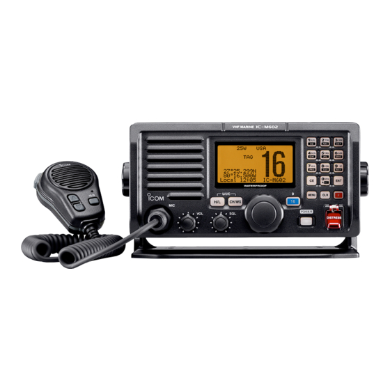
Vhf marine transceiver
Hide thumbs
Also See for IC-M602:
- Instruction manual (78 pages) ,
- Service manual (7 pages) ,
- Instruction manual (86 pages)
Table of Contents
Advertisement
Advertisement
Table of Contents

Subscribe to Our Youtube Channel
Related Manuals for Icom IC-M602


Summary of Contents for Icom IC-M602
- Page 1 SERVICE MANUAL VHF MARINE TRANSCEIVER iM602...
- Page 2 This service manual describes the latest service information NEVER connect the transceiver to an AC outlet or to a DC for the IC-M602 VHF MARINE TRANSCEIVER at the time of power supply that uses more than 15.6 V. This will ruin the transceiver.
-
Page 3: Table Of Contents
IC-M602 ........ -
Page 4: Specifications
SECTION 1 SPECIFICATIONS ‘ ‘ GENERAL • Frequency coverage : 156.020–157.425 MHz (Tx) 156.050–163.275 MHz (Rx) • Mode : 16K0G3E (FM) / 16K0G2B (DSC) • Usable channels : All international, U.S.A and Canadian channels, plus, 10 Weather channels • Power supply requirement : 13.8 V DC ±15 % (negative ground) •... -
Page 5: Vhf Marine Channel List
‘ ‘ VHF MARINE CHANNEL LIST Channel No. Frequency (MHz) Channel No. Frequency (MHz) Channel No. Frequency (MHz) Transmit Receive Transmit Receive Transmit Receive 156.050 160.650 157.050 157.050 156.525 156.525 156.050 156.050 RX only 161.650 156.575 156.575 156.100 160.700 157.100 161.700 156.625 156.625... -
Page 6: Inside Views
SECTION 2 INSIDE VIEWS 2-1 IC-M602 • MAIN UNIT RF amplifier (Q1: 3SK294) RF amplifier (for CH70) (Q7: 3SK294) Antenna switch circuit 1st mixer circuit (for CH70) 1st mixer circuit D21: HSB88WS D11: HSB88WS L48, L49: 617DB-1327=P3 L18, L19: 617DB-1327=P3... - Page 7 2-2 HM-127 (OPTIONAL UNIT) • TOP VIEW (DS1: A0119) • BOTTOM VIEW System clock (X1: CSTCC4.91MG) (IC1: µPD789405AGK-A30-9EU) Dimmer circuit Data buffer circuit Reset IC 8V regulator (IC7: S-80928CNMC) (IC6: TA7808F) 5V regulator Volume IC (IC5: TA78L05F) (IC3: M62429FP) AF/MIC switch (IC9: TC4W53FU) AF amplifier MIC amplifier...
- Page 8 SECTION 3 DISASSEMBLY AND OPTIONS INSTRUCTIONS CAUTION: DISCONNECT the DC power cable from the transceiver before performing any work on the transceiver. Otherwise, there is danger of electric shock and/or equip- ment damage. • Opening the transceiver case • Removing the MAIN unit 1 Unscrew 6 screws A, and remove the front unit.
- Page 9 • Removing the AF unit 1 Disconnect 4 connectors from J5, J8, J9 and J10. 2 Disconnect 2 flat cables from J2 and J4 3 Unscrew 2 screws H, and remove 2 clips I, J. 4 Unscrew 3 screws K, and remove the AF unit. •...
-
Page 10: Circuit Description
SECTION 4 CIRCUIT DESCRIPTION 4-1 RECEIVER CIRCUITS 4-1-3 1ST MIXER AND 1ST IF CIRCUITS (MAIN UNIT) 4-1-1 ANTENNA SWITCHING CIRCUIT (MAIN UNIT) The 1st mixer circuit converts the received signal into a fixed The antenna switching circuit functions as a low-pass filter frequency of the 1st IF signal with a 1st LO (VCO output) fre- while receiving and as resonator circuit while transmitting. - Page 11 4-1-4 2ND IF AND DEMODULATOR CIRCUITS The FM detector circuit employs a quadrature detection method (linear phase detection), which uses a ceramic dis- (MAIN UNIT) criminator (X2) for phase delay to obtain a non-adjusting cir- The 2nd mixer circuit converts the 1st IF signal into a 2nd IF cuit.
-
Page 12: Transmitter Circuits
4-1-5 AF AMPLIFIER CIRCUIT (AF UNIT) The amplified signals are applied to the IDC amplifier (IC8a, pin 2) via the analog switch (IC7, pins 2, 3, 9), and are then The AF amplifier circuit amplifies the demodulated signals to passed through the splatter filter (IC8b) to suppress unwant- drive a speaker. -
Page 13: Pll Circuits
4-2-5 APC CIRCUIT (MAIN UNIT) 4-3-2 TX AND CHANNEL 70 (RX) LOOPS The APC (Automatic Power Controller) circuit stabilizes the The generated signal at the TX-VCO/CHANNEL 70-VCO TX output power. (Q18, D39, D40) enters the PLL IC (IC2, pin 2) and is divid- ed at the programmable divider section and is then applied The RF output signal from the power amplifier (IC13) is to the phase detector section. -
Page 14: Dsc Circuits
4-3-4 VCO CIRCUIT (MAIN UNIT) The signalis passed through the splatter filter (AF unit; IC8b) to suppress unwanted 3 kHz or higher signals. The filtered • TX-VCO/CHANNEL 70-VCO (RX) CIRCUITS signals are then applied to the TX modulation circuit via the The VCO outputs from TX-VCO/CHANNEL 70-VCO (Q18) D/A converter IC (MAIN unit;... -
Page 15: Power Supply Circuits
High : Bypassing the scrambler unit. Outputs sound signals to the HM-127. AFSUB High : Sounding from HM-127. Outputs voice signals from IC-M602 to INCMH HM-127 using intercom function. High : While receiving. Outputs voice signals from HM-127 to INCHM IC-M602 using intercom function. - Page 16 4-7-3 CPU (LOGIC BOARD; IC1) Port Port Description Description number name number name Input port for PLL unlock signal from Input port for the low-battery detecting UNLK the PLL IC (MAIN unit; IC12, pin 7). signal. Low battery indicator appears LBAT High : While PLL is unlocked.
-
Page 17: Adjustment Procedures
(–127 dBm to –17 dBm) I CONNECTION CAUTION! DO NOT transmit while an SSG is connected to the antenna connector. IC-M602 rear panel to the antenna connector Standard signal generator 0.1 300 MHz 127 dBm to 17 dBm (0.1 V to 32 mV) -
Page 18: Pll Adjustments
5-2 PLL ADJUSTMENTS ADJUSTMENT MEASUREMENT POINT ADJUSTMENT ADJUSTMENT CONDITION VALUE UNIT LOCATION UNIT ADJUST LOCK • Operating channel : ch P2 MAIN Connect a digital 3.8 V – 4.0 V MAIN VOLTAGE • Receiving multi-meter or oscil- loscope to check point CP1. -
Page 19: Receiver Adjustments
5-3 RECEIVER ADJUSTMENTS ADJUSTMENT MEASUREMENT POINT ADJUSTMENT ADJUSTMENT CONDITION VALUE UNIT LOCATION UNIT ADJUST SENSITIVITY • Operating channel : ch 16 MAIN Connect a tracking Set the flat wave MAIN (Except • Connect a tracking generator’s generator’s input to form as shown below. output to the antenna connector the MAIN unit;... - Page 20 • MAIN UNIT TOP VIEW RX sensitivity adjustment for channel 70 RX sensitivity adjustment for other channels RX sensitivity check point 5 - 4...
-
Page 21: Parts List
SECTION 6 PARTS LIST 6-1 IC-M602 [LOGIC BOARD] [SQL BOARD] ORDER ORDER DESCRIPTION DESCRIPTION 7210002360 VARIABLE TP96N97-15F-10KB-1301 1140010584 S.IC HD64F2633F25 (FX2577A-4) 1110005770 S.IC S-80942CNMC-G9C-T2 1130007450 S.IC RTC-4553A 0910055532 PCB B 5885B 1140009240 S.IC HN58X24128FPI 1180002420 S.IC S-818A33AUC-BGN-T2 1510000580 S.TRANSISTOR 2SA1362-GR (TE85R) 1590000430 S.TRANSISTOR DTC144EUA T106... - Page 22 [LOGIC BOARD] [LOGIC BOARD] ORDER ORDER DESCRIPTION DESCRIPTION 7030003440 S.RESISTOR ERJ3GEYJ 102 V (1 kΩ) 4550006460 S.TANTALUM ECST1VX225R 7030003560 S.RESISTOR ERJ3GEYJ 103 V (10 kΩ) 4550006460 S.TANTALUM ECST1VX225R 7030003500 S.RESISTOR ERJ3GEYJ 332 V (3.3 kΩ) 4550006460 S.TANTALUM ECST1VX225R ERJ3GEYJ 221 V (220 Ω) 7030003360 S.RESISTOR 4550006460 S.TANTALUM ECST1VX225R...
- Page 23 [LOGIC BOARD] [AF UNIT] ORDER ORDER DESCRIPTION DESCRIPTION DS20 5040002660 S.LED FY1101F-TR (LED) 7030003580 S.RESISTOR ERJ3GEYJ 153 V (15 kΩ) DS21 5040002660 S.LED FY1101F-TR (LED) 7030003450 S.RESISTOR ERJ3GEYJ 122 V (1.2 kΩ) DS22 5040002660 S.LED FY1101F-TR (LED) 7030003800 S.RESISTOR ERJ3GEYJ 105 V (1 MΩ) DS23 5040002660 S.LED FY1101F-TR (LED)
- Page 24 [AF UNIT] [AF UNIT] ORDER ORDER DESCRIPTION DESCRIPTION ERJ3GEYJ 680 V (68 Ω) R212 7030003300 S.RESISTOR 4030012600 S.CERAMIC C2012 JB 1A 105M-T R213 7030003500 S.RESISTOR ERJ3GEYJ 332 V (3.3 kΩ) 4030006870 S.CERAMIC C1608 JB 1H 222K-T R214 7030003500 S.RESISTOR ERJ3GEYJ 332 V (3.3 kΩ) 4030006850 S.CERAMIC C1608 JB 1H 471K-T ERJ3GEYJ 680 V (68 Ω)
- Page 25 [AF UNIT] [MAIN UNIT] ORDER ORDER DESCRIPTION DESCRIPTION C281 4030006850 S.CERAMIC C1608 JB 1H 471K-T 1710001080 DIODE XB15A308 C282 4030011810 S.CERAMIC C1608 JB 1A 224K-T 1750000580 S.DIODE 1SV307 (TPH3) C283 4030011810 S.CERAMIC C1608 JB 1A 224K-T 1750000580 S.DIODE 1SV307 (TPH3) C301 4510004630 S.ELECTROLYTIC ECEV1CA100SR 1750000430 S.DIODE...
- Page 26 [MAIN UNIT] [MAIN UNIT] ORDER ORDER DESCRIPTION DESCRIPTION 6200003280 S.COIL NL 252018T-2R2J R145 7030003560 S.RESISTOR ERJ3GEYJ 103 V (10 kΩ) 6200009560 S.COIL MLG1608B R10J-T R146 7030003560 S.RESISTOR ERJ3GEYJ 103 V (10 kΩ) 6200009560 S.COIL MLG1608B R10J-T R147 7030003560 S.RESISTOR ERJ3GEYJ 103 V (10 kΩ) 6200005740 S.COIL ELJRE 47NG-F R148...
- Page 27 [MAIN UNIT] [MAIN UNIT] ORDER ORDER DESCRIPTION DESCRIPTION R283 7030003460 S.RESISTOR ERJ3GEYJ 152 V (1.5 kΩ) 4030009550 S.CERAMIC C1608 CH 1H 2R5B-T R284 7030003640 S.RESISTOR ERJ3GEYJ 473 V (47 kΩ) 4030009520 S.CERAMIC C1608 CH 1H 020B-T R285 7030003500 S.RESISTOR ERJ3GEYJ 332 V (3.3 kΩ) 4030006860 S.CERAMIC C1608 JB 1H 102K-T R286...
- Page 28 [MAIN UNIT] [MAIN UNIT] ORDER ORDER DESCRIPTION DESCRIPTION C194 4030006850 S.CERAMIC C1608 JB 1H 471K-T C309 4030006860 S.CERAMIC C1608 JB 1H 102K-T C195 4030006900 S.CERAMIC C1608 JB 1H 103K-T C316 4030006860 S.CERAMIC C1608 JB 1H 102K-T C196 4030006900 S.CERAMIC C1608 JB 1H 103K-T C317 4030006860 S.CERAMIC C1608 JB 1H 102K-T...
- Page 29 6-2 HM-136 [MAIN UNIT] ORDER [MAIN UNIT] DESCRIPTION ORDER DESCRIPTION C432 4030006860 S.CERAMIC C1608 JB 1H 102K-T C433 4030006860 S.CERAMIC C1608 JB 1H 102K-T 7010006890 RESISTOR R20J 12 kΩ C434 4030006860 S.CERAMIC C1608 JB 1H 102K-T 7010006880 RESISTOR R20J 6.8 kΩ C435 4030006860 S.CERAMIC C1608 JB 1H 102K-T...
- Page 30 [MAIN UNIT] [MAIN UNIT] ORDER ORDER DESCRIPTION DESCRIPTION 7030003560 S.RESISTOR ERJ3GEYJ 103 V (10 kΩ) 4510006220 S.ELECTROLYTIC ECEV1CA101UP 7030003560 S.RESISTOR ERJ3GEYJ 103 V (10 kΩ) 4510006250 S.ELECTROLYTIC ECEV1CA331UP 7030003560 S.RESISTOR ERJ3GEYJ 103 V (10 kΩ) 4030006900 S.CERAMIC C1608 JB 1H 103K-T 7030003560 S.RESISTOR ERJ3GEYJ 103 V (10 kΩ) 4510005430 S.ELECTROLYTIC ECEV0JA220SR...
-
Page 31: Mechanical Parts And Disassembly
SECTION 7 MECHANICAL PARTS AND DISASSEMBLY 7-1 IC-M602 [CHASSIS PARTS] [FRONT UNIT] REF. ORDER REF. ORDER DESCRIPTION QTY. DESCRIPTION QTY. 6510004880 Antenna connector MR-DS-E 01 8900011470 Cable OPC-1177 8900011450 Cable OPC-1175 8210019180 2577 front panel assembly [BLACK] 8900011460 Cable OPC-1176... - Page 32 MP13 (C) MP14 (C) MP19 (C) Unit abbreviations (C): CHASSIS PARTS MP8 (C) (M): MAIN UNIT MP2 (C) MP7 (C) (F): FRONT UNIT (L): LOGIC BOARD (CO): CONNECT UNIT (D): DIAL BOARD (S): SQL BOARD (V): VR BOARD MP4 (M) MP11 (C) MP5 (M) MP7 (M)
- Page 33 MP12 8930053750 2417 plate MP7 (C) MP12 8820001150 2352 screw MP13 8210017250 2417 rear panel [BLACK] MP13 8850001850 ICOM washer (Y) 8210017300 2417 rear panel (A) [WHITE] MP11 (C) MP14 8930052340 O ring (AE) MP14 8310049970 2417 R-plate MP15 8930052350...
- Page 34 SECTION 8 SEMI-CONDUCTOR INFORMATION • TRANSSISTORS AND FET’S • DIODES 2SA1362 GR 2SA1576A T106 R 2SA1577 T106 Q 2SB1132 T100 R 2SB1143 S 1SS355 1SV214 1SV288 1SV307 1SV308 (Symbol: AEG) (Symbol: FR) (Symbol: HQ) (Symbol: BAR) (Symbol: B1143) (Symbol: A) (Symbol: T1) (Symbol: TJ) (Symbol: TX)
- Page 35 SECTION 9 BOARD LAYOUTS 9-1 VR BOARD 9-4 CONNECT UNIT • TOP VIEW VOL1 VOL2 to AF unit J6 9-2 SQL BOARD to AF unit W6 to AF unit J4 SQLG SQLV • BOTTOM VIEW (CONNECT UNIT) SQL5V to LOGIC board J7 COMMAND COMMAND...
-
Page 36: Logic Board
9-5 LOGIC BOARD • TOP VIEW MENU CH/WX DISTRESS POWER 9 - 2... - Page 37 • BOTTOM VIEW (LOGIC BOARD) to MAIN unit J1 to FLASH to LCD to DIAL/SQL board J1 to FRONT unit W1 to AF unit J1 9 - 3...
-
Page 38: Main Unit
9-6 MAIN UNIT • TOP VIEW TXDET SEND DASTB TMUTE ATT2 ATT1 UNLK PSTB PDATA CHASSIS DEC2 RXADJ DEC1 WXDET to AF unit J5 TEMP to LOGIC BOARD J1 PDATA HLVL to AF unit J2 9 - 4... - Page 39 • BOTTOM VIEW (MAIN UNIT) 9 - 5...
-
Page 40: Af Unit
9-7 AF UNIT • TOP VIEW to LOGIC board J2 to VR to FRONT board J1 unit W1 to MAIN unit J2 to CONNECT unit J5 HALL- to CHASSIS HALL+ to CONNECT/CONNECT-A to Optional to CHASSIS W1 unit J4 unit UT-112 9 - 6... - Page 41 • BOTTOM VIEW (AF UNIT) to MAIN unit 9 - 7...
- Page 42 9-8 HM-136 9-9 HM-127 (OPTIONAL UNIT) • TOP VIEW • TOP VIEW to Speaker MICE to IC-M601/M602 FRONT unit W1 to Microphone 9 - 8...
- Page 43 • BOTTOM VIEW (HM-127) • BOTTOM VIEW (HM-136) SCAN PWRC RRXDA RTXDA PTTC 16/9 MICG AF/MIC to CONNECT [IC-M602] CONNECT-A [IC-M601] unit J1 to Speaker 9 - 9...
-
Page 44: Block Diagram
SECTION 10 BLOCK DIAGRAM MAIN UNIT For other channels Q3, Q4 L18, L19 617DB-1327=P3 ALFYM450F=K 2SC4215 FL-285 PMBFJ310 D11 HSB88WS 3SK294 ACC UNIT CERAMIC XTAL HM-136 31.05MHz TA31136FN IC3A 2SC5110 NJM2902V BUFF WXDEC 2ND IF Q12 PMBFJ310 D32, D33 HVC358B 2SC4215 D3, D4 1SV307... -
Page 45: Wiring Diagram
SECTION 11 WIRING DIAGRAM CHASSIS FRONT UNIT MICG HAIL+ HAIL+ VR BOARD HAIL- HAIL- VOL1 VOL1 VOL2 VOL2 OPC-1176 W1 OPC-1175 LOGIC BOARD PDATA OPTIN OPSTB AF UNIT SCON CONNECT/-A UNIT MICI DETI MICO DETO NMEAIN+ NMEAIN+ NMEAIN+ SCOUT SCOUT NMEAIN- NMEAIN- NMEAOUT+... -
Page 46: Voltage Diagram
SECTION 12 VOLTAGE DIAGRAMS 12-1 LOGIC BOARD LOGIC BOARD D11-D18 3.3V 3.3V 3.3V HSU88 R101 47k R102 10k R91-R98 R103 10k R33 15k S818A33AVC-BGN-T2 TEMP TEMP 3.3V VOUT DTC144EU ON/OFF WXDEC WXDEC DEC1 DEC1 DA204K R31 1k RXADJ RXADJ SPPH22014A DEC2 DEC2 R32 1k... -
Page 47: Main Unit
12-2 MAIN UNIT MAIN UNIT 1.2V at -8dBu TEMP R306 R307 R201 R308 WXDET R309 NJM2125F C254 R204 DEC1 R310 0.001 RXADJ R311 220µ DEC2 R312 C253 LOCK : 0.0V C251 5p UNLOCK: 4.83V R313 3.72V IC12 µPD3140GS R314 R299 VCC1 GND1 C102... - Page 48 MC138-E544ENAS-100014 MC138-E544ENAS-100014 MC138-E544ENAS-100014 R105 C150 4.7µ 0.001 R116 10 C184 47p CHASSIS PMBFJ310 ALFYM450F=K CR-744 (21.25 MHz) R236 LW-25 IC13 IC-M602 only LA-243 XB15A308 RA35H1516M 2SA1577 13.8V C345 LA-243 XB15A308 0.001 LA-243 LA-243 R297 2.2k C338 TX: 7.37V RX: 0.0V...
-
Page 49: Af Unit
12-3 AF UNIT VR BOARD AF UNIT J1 TP96N97-15F-10KA-2345 RL1 FTR-P3CP012W1 VOL2 to MAIN VOL1 unit TA78L05F TA7808S VR BOARD 1.2k SCOUT 13.8V DA204K to CHASSIS IC17 IC18 1SS355 BU4094BCFV BU4094BCFV DTC144EU FTR F3AA012E STRB STRB INT SP ON: 4.89V DATA OENA DATA... -
Page 50: Hm-136
12-4 HM-136 UP KEY : 2.0V DOWN KEY : 3.0V 16/9 KEY : 3.8V 6.8k W1 (CHASSIS) DOWN 16/9 HANGER 470p 470p 12 - 5... -
Page 51: Hm-127 (Optional Unit)
12-5 HM-127 (OPTIONAL UNIT) MAIN UNIT CHASSIS TA7368F POUT PWGND PREGND PHASE 11.1V RIPPLE 0.0047 SML-311YT SML-311YT SML-311YT 2SJ144 DOWN SCAN M62429FP DS10 SML-311YT 100k 100k VIN1 VIN2 VOUT1 VOUT2 470k VRDAT DATA DOWN MICG FY1101F-TR A0119 DIM3 : 8.2V VRCK 2 : 7.1V 3.3V... - Page 52 Unit 9, Sea St., Herne Bay, Kent, CT6 8LD, U.K. Phone : +44 (01227) 741741 Fax : +44 (01227) 741742 : http://www.icomuk.co.uk Icom (Australia) Pty. Ltd. E-mail : info@icomuk.co.uk A.B.N. 88 006 092 575 290-294 Albert Street, Brunswick, Victoria, 3056, Australia Icom France S.a...
- Page 53 S-13908HZ-C2-q 1-1-32, Kamiminami, Hirano-ku, Osaka 547-0003, Japan © 2002, 2003 Icom Inc.
Need help?
Do you have a question about the IC-M602 and is the answer not in the manual?
Questions and answers