Advertisement
Service
Manual
1.
TECHNICAL SPECIFICATION ............................................................................... 1
2.
BLOCK DIAGRAM .................................................................................................. 2
3.
WIRING DIAGRAM ................................................................................................. 3
4.
ADJUSTMENT PROCEDURE ................................................................................ 5
5.
SCHEMATIC DIAGRAM AND PARTS LOCATION ............................................... 10
6.
MICROPROCESSOR AND IC DATA .................................................................... 17
7.
EXPLODED VIEW AND PARTS LIST ................................................................... 19
8.
ELECTRICAL PARTS LIST ................................................................................... 22
Please use this service manual with referring to the user guide (D.F.U) without fail.
Printed in Japan
TABLE OF CONTENTS
- SD4050 -
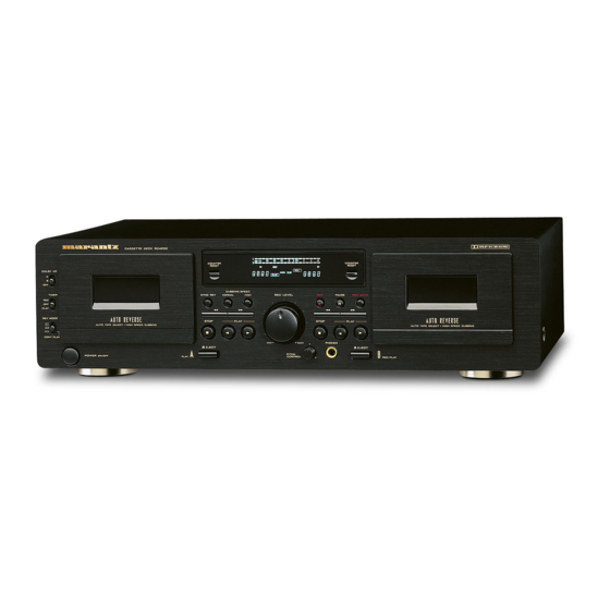
SD4050 /
N1B, /U1B, /F1B
Cassette Deck
286W855010 AO
3120 785 22012
First Issue:1999.08
Advertisement

Subscribe to Our Youtube Channel
Related Manuals for Marantz SD4050 /N1B


Summary of Contents for Marantz SD4050 /N1B
-
Page 1: Table Of Contents
Service SD4050 / N1B, /U1B, /F1B Manual Cassette Deck TABLE OF CONTENTS TECHNICAL SPECIFICATION ................1 BLOCK DIAGRAM ....................2 WIRING DIAGRAM ....................3 ADJUSTMENT PROCEDURE ................5 SCHEMATIC DIAGRAM AND PARTS LOCATION ..........10 MICROPROCESSOR AND IC DATA ..............17 EXPLODED VIEW AND PARTS LIST .............. - Page 2 MARANTZ Parts for your equipment are generally available to our National Marantz Subsidiary or Agent. ORDERING PARTS : Parts can be ordered either by mail or by Fax.. In both cases, the correct part number has to be specified.
-
Page 3: Technical Specification
1. TECHNICAL SPECIFICATION Track System : 4-track, 2-channel stereo Deck I ; 1 Playback (Rotating) Heads : Deck II ; 1 Erase and 1 Record/ Playback (Rotating) Type of Tape : Cassette tape C-60 and C-90 (Philips type) Tape Speeds : 4.8 cm/sec, 4.9 cm/sec (When high speed dubbing) Motors :... -
Page 4: Block Diagram
2. BLOCK DIAGRAM... -
Page 5: Wiring Diagram
3. WIRING DIAGRAM PCB MAIN PCB CONTROL MECH I J307 P307 J319 DECK I PLAY HEAD PLAY P301 PLAY HEAD CrO2 J308 P308 TAPE DECK II MECH II R/P HEAD P302 J320 R/P HEAD E HEAD P309 PLAY J311 J503 P503 P303 CrO2... -
Page 6: Adjustment Procedure
4. ADJUSTMENT PROCEDURE 4-1 MECHANICAL ADJUSTMENT 4-2 ELECTRICAL ADJUSTMENT 4-1-1 Wow and flutter (playback method) 4-2-1 Precautions In both FWD and REV play modes, these measurements Before performing adjustments and checks clean and should be made at the beginning, middle, and the end of the demagnetize the entire tape parh. - Page 7 4-2-3 Playback performance Deck settings : TEAC test tapes : Mode : PLAY MTT-150C : For Dolby lavel calibration DOLBY NR Switch : OFF MTT-25702 : For playback frequency response check NORMAL tape MTT-5513 : For S/N check NORMAL tape MEASURING ITEM SETTING...
- Page 8 4-2-4 Recording performance TEAC recording test tapes : Deck settings : MTT-5513 : For NORMAL Mode : REC/PLAY MTT-5563 : For C DOLBY NR Switch : OFF MTT-5572 : For METAL REC LEVEL Control : Specified position (Item 8) MEASURING ITEM SETTING ADJUSTMENTS...
- Page 9 MEASURING ITEM SETTING REMARKS INPUT SIGNAL ADJUSTMENTS RESULT Ratio of the 1kHz 17. Erase recorded portion to the Connection:Fig. 2-3 LINE IN: Check 65dB min. efficiency erased portion. TAPE: MTT-5572 1kHz/+1dB 1kHz B.P.F in Ratio of the 1kHz 18. REC MUTE recorded portion to the Connection:Fig.
-
Page 10: Schematic Diagram And Parts Location
5. SCHEMATIC DIAGRAM AND PARTS LOCATION CONTROL PCB/KEY PCB U50 Q6 U48 U54 U55 U45 PHONE PCB VR PCB SLIDE PCB... - Page 11 KEY PCB STOP I FWD I REV I BJ185GK SW15 1SS133T 1SS133T 1SS133T FF I REW I 1SS133T 1SS133T STOP II FWD II REV II REC II SW10 SW17 SW24 1SS133T 1SS133T 1SS133T 1SS133T FF II REW II PAUSE II MUTE SW11 SW18...
- Page 12 MAIN PCB/TR PCB Q302 Q303 U332 U309 U346 Q304 Q203 Q103 U366 U343 U340 U339 U335 U324 U345 U337 U312 Q301 U101 Q306 Q102 Q202 U330 U325 U331 U347 U327 U336 U305 U303 U342 U341 U201 U301 U302 U304 U329 U322 U328 U348...
- Page 13 C311 R124 R118 U101 C131 560P(CE) R132 C134 R106 C106 100K C135 0.001u 6.2K C119 4.7u50V DTC124ES 0.001u (CE) 0.01u 0.001u R138 R102 (CE) R139 C104 (CE) (CE) 220u10V C133 L101 R387 DECK I C302 R107 R140 R119 470P 100K 10u16V 6.8K 10K(B)
-
Page 14: Microprocessor And Ic Data
6. MICROPROCESSOR AND IC DATA 2. Block Diagram U42 : CXT82940 1. Pin Functions Pin code Functions (Port A) 8-bit I/O port. I/O can AN0 to AN7 A/D CONVERTER CLOCK PA0 to PA7 be set in a unit of SPC 700 GENERATOR CPU CORE PA0/AN0... -
Page 15: Exploded View And Parts List
7. EXPLODED VIEW AND PARTS LIST (VERS. :VERSION, U:U.S.A., F:JAPAN, K:FAR EAST, N:EUROPE) POS. VERS. PART NO. PART NO. DESCRIPTION COLOR (FOR PCS) (MJI) BONNET 9965 000 01104 MECH ASSY,PB CMAL2Z093A 286W304500 9965 000 01105 HOOK,EJECT (L) 286W258110 9965 000 01106 SPRING,HOOK L 286W115110 9965 000 01107 SPRING EJECT W-790R 286W115120... -
Page 16: Electrical Parts List
8. ELECTRICAL PARTS LIST NOTE ON SAFETY FOR FUSIBLE RESIST OR : ASSIGNMENT OF COMMON PARTS CODES. RESISTORS The suppliers and their type numbers of fusible resistors are as 1) GD05 x x x 140, Carbon film fixed resistor, 5% 1/4W follows ;... - Page 17 (VERS. :VERSION, U:U.S.A., F:JAPAN, K:FAR EAST, N:EUROPE) (VERS. :VERSION, U:U.S.A., F:JAPAN, K:FAR EAST, N:EUROPE) VERS. PART NO. VERS. POS. POS. PART NO. PART NO. PART NO. DESCRIPTION DESCRIPTION COLOR (FOR PCS) COLOR (FOR PCS) (MJI) (MJI) MAIN CIRCUIT BOARD C301 ELECT 1 F 50V CAPACITORS...
- Page 18 (VERS. :VERSION, U:U.S.A., F:JAPAN, K:FAR EAST, N:EUROPE) (VERS. :VERSION, U:U.S.A., F:JAPAN, K:FAR EAST, N:EUROPE) POS. VERS. PART NO. POS. VERS. PART NO. PART NO. PART NO. DESCRIPTION DESCRIPTION COLOR COLOR (FOR PCS) (FOR PCS) (MJI) (MJI) U342 4822 130 42593 DTA124ES BA10016210 R214 U343...
- Page 19 (VERS. :VERSION, U:U.S.A., F:JAPAN, K:FAR EAST, N:EUROPE) (VERS. :VERSION, U:U.S.A., F:JAPAN, K:FAR EAST, N:EUROPE) VERS. VERS. POS. PART NO. POS. PART NO. PART NO. PART NO. DESCRIPTION DESCRIPTION COLOR COLOR (FOR PCS) (FOR PCS) (MJI) (MJI) R350 SLIDE CIRCUIT BOARD R351 SW21 9965 000 01149 Switch Slide AXA 2-3...
- Page 20 (VERS. :VERSION, U:U.S.A., F:JAPAN, K:FAR EAST, N:EUROPE) (VERS. :VERSION, U:U.S.A., F:JAPAN, K:FAR EAST, N:EUROPE) VERS. VERS. POS. PART NO. POS. PART NO. PART NO. PART NO. DESCRIPTION DESCRIPTION COLOR (FOR PCS) COLOR (FOR PCS) (MJI) (MJI) DIODES 4822 130 80598 Zener Diode MTZJ22C *HD301680R 4822 130 31878 1N4003 HD200010AR...
Need help?
Do you have a question about the SD4050 /N1B and is the answer not in the manual?
Questions and answers