
Related Manuals for Nikon D90


Summary of Contents for Nikon D90
- Page 1 Airborne Digital Reconnaissance System (ADRS) Nikon D90 Camera Kit -Checklist and Operations Manual- V3.0 March 11, 2014 National Headquarters, Civil Air Patrol Advanced Technology Group...
- Page 2 AMOD Data Logger (if included in the kit) Spare AA and AAA batteries A cable may be enclosed that is used to connect the GP-1 GPS to a Nikon D200 camera. This cable is not for use with the D90 system.
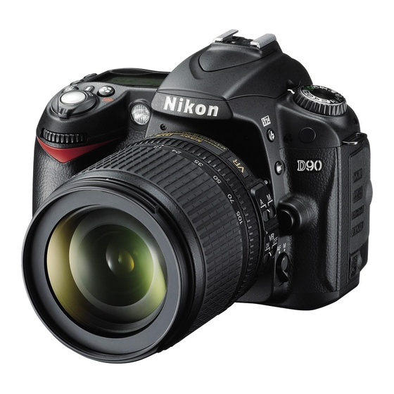
- Page 3 Photos of equipment located in the D90 System Case D90 camera with attachments Battery pack note: lens shield not used...
- Page 4 AMOD Data Logger with USB cable (not all kits were delivered with this item) An inexpensive tripod or monopod is not included in the D90 Kit provided by National Headquarters. Local purchase is recommended. Make sure it has an articulating camera mount so camera pointing angle can be adjusted up and down.
- Page 5 Plug in each battery pack, one at a time, and bring the batteries to full charge. The indicator light will flash during charging. When fully charged, the light will illuminate continuously. 1.3 Nikon D90 Camera Pre-mission Initiation Verify the camera is turned off Install memory card (card may already be in the camera)
- Page 6 If the GP-1 cable is not attached to the GPS, do so by selecting the smaller of the two connector ends (the end does not have the words Nikon or CA 90 on it) and pushing it into the side of the GP-1 marked “camera”...
- Page 7 Install Camera Batteries The Nikon MB-D80 Multi-Power Battery Pack is capable of holding two rechargeable batteries or six AA batteries. The camera will work properly with only one rechargeable battery installed. Two batteries give extended operation time. The six AA batteries are only used if the rechargeable batteries are discharged and there is no electrical power available to operate the charger, or if time is limited to allow for recharge.
- Page 8 Reset the Camera Press the +/- and AF buttons. Hold them pressed for four seconds. The two buttons have green dots next to them. The Control Panel Display will flash to confirm reset has been completed. Control Panel Display Clear the memory card Press the Menu button to bring up the Menu Display on the Monitor.
- Page 9 Selector in order to navigate the various Menu screens. Press the up and down keys to find the “Shooting Menu”. Press the right key and then the up and/or down keys to select ISO sensitivity setting. Press the right key to go to the ISO selection screen. Press the up and/or down keys to select the ISO value;...
- Page 10 The coordination is done by matching photo time and Data Logger time. Confirm the D90 camera is set to Coordinated Universal Time in London, England (UTC 0). Push the camera menu button. Press the Multi Selector left button and then press the up and/or down buttons until the “Setup Menu”...
- Page 11 1.6 AMOD Data Tracker Install fresh batteries as follows: 1. Remove the back cover 2. Install three AA batteries as shown. The AMOD Tracker can use either rechargeable or non- rechargeable batteries. If rechargeable batteries are used, they must be charged with an external battery charger. Fresh batteries will provide approximately 15 hours of use.
- Page 12 4 seconds. The Multi Function Timer Remote Control included with the D90 camera system kit will automate the shutter release. If your kit has a different timer than that shown in this section, refer to its manual for how to accomplish the following.
- Page 13 The Timer Remote Control cable plugs into the right side of the Nikon GP-1 GPS. The arrow on the unit’s cable faces up when plugged into the GP-1. Activate the Timer Remote Control by pushing the Start/Stop button.
- Page 14 Put the lens cap back on the camera! 2.0 Pre-Mission Planning 2.1 Identify Customer Requirements The flight crew needs the following information to assure successful acquisition of the aerial photographs required by the customer: Type of mission. The major types are: ...
- Page 15 Camera Pointing Angle Camera pointing angle is the angle below the horizon. In a Cessna 182 or Cessna 172 with a photo window it is not possible to get a pointing angle much greater than 45 degrees. Smaller angles result in the photos being greater in extent perpendicular to the direction of flight and thus lower resolution at ground-level.
- Page 16 Resolution at the center of the photo will be 2.3 inches! Important – the data in the table applies to the Nikon D90 camera. Most of the data also applies to the Nikon D200 although resolution values will be reduced slightly. For other cameras, the...
- Page 17 For shallow camera pointing angles (see the 15 degree entry) the dimensions of each photograph for a 50 mm lens focal length become very large (approximately 2240 feet horizontal by 8900 feet perpendicular to the aircraft). Resolution is lower at the center of the camera axis;...
- Page 18 Internet connection to work. Google Earth is a better alternative where a Web connection is available. DeLorme Street Atlas is not included in the D90 kit. It is a local-purchase item; Squadrons may elect to use other computer tools to determine waypoint information.
- Page 19 The Myakka Bridge in Charlotte County, FL was located by scrolling around the map. If an address is available for the target, it can be entered to find it on the map using the search feature. The computer cursor is pointed at the center of the bridge. The longitude and latitude of the pointer is listed to the right of the map.
- Page 20 The Draw tool has been used surround the target with a square box with each side 1 mile from the center of the target. The cursor is then placed over each corner point, in turn, so that the Lat/long of each corner point can be determined for entry into...
- Page 21 3.0 Flying the Mission 3.1 Pre Engine Start Take a picture of the tail number of the aircraft. Brief the pilot and observer on missions details; altitude, ground speed, target location(s) and type. Agree on how you will direct the aircraft once in the target area. Make sure the observer understands that he or she must determine camera direction for each photo (aircraft heading minus 90 degrees for a photo window on the left side of the aircraft) and record it in the photo log.
- Page 22 3.2 Flight Segment Tell the pilot you are ready for engine start. Once the engine is running, make sure your can talk to the pilot and observer using the intercom. If not, do not proceed until this is resolved. You must be able to talk to the pilot in order to give steering directions once in the target area at to provide photo ID for entry into the shooting log that the observer is responsible for.
- Page 23 3.3 After the Flight Turn off camera, the AMOD Data Tracker and the Remote Timer Disconnect cables as required Replace the camera lens cap Take the camera and the data tracker to mission base for photo processing 3.4 After Photo Processing ...
- Page 24 4.0 Spot Photography Forms 4.1 Spot Photography Circular Pattern Worksheet Distance off target Target Exit Entry Point Target description: ________________________________________________ Mission number: _______________ Sortie Number: _________________ Crew: PIC________________ OBS__________________ AP________________ 2 mile from target: altitude _______ft Entry point: Latitude ___________ Longitude ___________ Center of target: Latitude...
- Page 25 4.2 Spot Photography Rectangular Pattern Worksheet Distance from target Lt. Col. Edmund H Smith, Jr. 3/11/2014...
Need help?
Do you have a question about the D90 and is the answer not in the manual?
Questions and answers