Table of Contents
Advertisement
Advertisement
Table of Contents

Subscribe to Our Youtube Channel
Related Manuals for Reebok EDGE series


Summary of Contents for Reebok EDGE series
- Page 3 Dear Customer, We are pleased, that you have chosen a Reebok Fitness Equipment. This quality product has been designed for in-home use and has been tested and certified according to the European Norm EN 957-1/9. Please carefully read the instructions prior to assembly and first use and be sure to keep the instructions for reference and maintenance.
- Page 4 Technical support: tel: 0044 (0) 871 474 2614 e-mail: techsupport@rfeinternational.com Advice The owner’s manual is only for the customer reference. Reebok can not guarantee for mistakes occurring due to translation or change in technical specification of the product.
- Page 5 • Product-Preparation: Follow the steps of the assembly instruction carefully. • Product-Preparation: Only use suitable tools for assembly and ask for assistance if necessary. • Product-Preparation: Only use original Reebok parts as delivered (see checklist).
- Page 6 For this reason, worn or damaged parts should be replaced immediately and the equipment taken out of use until this has been done. • Product-Maintenance: Only use original Reebok spare parts. • Product-Maintenance: Do not under any circumstances carry out electrical repairs or alterations yourself.
- Page 7 Check List M8x12mm M8x20mm M4x15mm M8x65mm 8x17x1.5 12 x 19 x 8.5x20x2 6 mm M6X14mm M8X15mm 10 mm 6 mm 5 mm 17 mm...
- Page 8 Assembly instruction 236-1x 235-1x 218-1x 236-1x 235-1x 218-1x...
- Page 9 227-4x 714-1x 212-1x 715-1x 714-1x 212-1x 715-1x 10²-2x 220-2x 122-2x 212-2x 220-2x 122-2x...
- Page 10 119-1x 220-1x 219-1x 119-1x 220-1x 219-1x Front Rear 227-4x 227-4x...
- Page 11 227-1x 227-2x 210-4x 210-4x 227-2x 227-2x...
- Page 12 Transport...
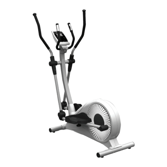
- Page 13 Correct Use Proper Ergonomic Positioning: Please refer to the diagram to the left as indication of the proper training position. Mount and dismount the equipment: Select any flank of the equipment, which flank you can easy and comfortable to move your foot to mount on or dismount from the equipment.
-
Page 14: Exploded View
Exploded view 411 406 408 403 210 212 204 220 119 233 233 227 205 212 220... - Page 15 Spare Part List Quantity Part No. Part name M8X65 Bolt Ø 8X17X1.5 Washer Rear Stabilizer Bushing Stabilizer Tube End Cap Transportation Wheel set Speed sensor Rear Stabilizer Tube adjustment foot Front Stabilizer Tube foot 6004Z Bearing Front Stabilizer M5X14 Screw Main Frame Lower section upright bushing M8X15X15screw...
- Page 16 Lower Handlebar Cover-Left Lower Handlebar Cover-Right M6X14 Screw Ø 8.5 x20 Washer Ø 8 Spring Washer 7 Pin Speed Sensor Wire Handlebar end cap Fixed Handlebar end cap Hand Pulse Sensor-Upper Hand Pulse Sensor-Lower M4X15 Screw Speed sensor Wire upper M3X12 Screw Handle pulse sensor wire Handlebar bearing bushing upper OD20X14...
- Page 17 Nut M10x17x4 Flywheel D-Shaped Holder Flywheel Aluminium Disk Flywheel Driving Belt pulley Flywheel axle M10x100.8 M6x6x6 mm screw Nut M10x17x6 Flywheel Ring-Shaped Holder M4X45 Screw Tension Bracket Adjustment Base Shaft M10x39 Ø 10x20X1.5 Washer 6300 Bearing M10 Nut Magnet bracket adjust bolt 10X73x23 M5X8x8 Screw Ø...
- Page 18 Rear Foot Plate Tube rear Cover-Upper Rear Foot Plate Tube rear Cover-Lower Front Foot Plate Tube front Cover-Left Front Foot Plate Tube front Cover-Right Foot Plate Fix Bolt Foot Plate fix Knob Overlay Console housing -Upper Battery Cap Upright upper Cover-Rear Upright upper Cover-Front Console housing -lower PC Board...
- Page 19 COMPUTER INSRUCTION Functions and Features: 1. Start: Allows you to start the computer just press the START key without selecting a program. TIME automatically begins to count up from zero. Use the UP and DOWN keys to adjust the resistance. 2.
-
Page 20: Key Function
1. START/STOP key: a. During the exercise mode, press the key to STOP exercise. b. During the stop mode, press the key to START exercise. c. Press this key can allow you to quickly start the computer without selecting a program. For Manual workout only. Time automatically begins to count up from zero 2. -
Page 21: Preset Program Operations
Preset Program: Rolling, Valley, Fat Burn, Ramp, and Mountain Program PROGRAM 2 to PROGRAM 6 is the preset programs. Users can exercise with different level of loading in different intervals as the profiles show. Users may exercise in any desirous of resistance level (Adjusting by UP/DOWN key during the workout) with a period of time or a number of calories or a certain distance. -
Page 22: Error Message
your exercise TIME. Press ENTER key to confirm your desired workout TIME. 4. The DISTANCE will flash and you can press UP or DOWN keys to setting your target DISTANCE. Press ENTER key to confirm your desired workout DISTANCE. 5. The CAL will flash and you can press UP or DOWN keys to setting your exercise CALORIES. - Page 23 seconds then the gear motor’s driver will be cut off immediately and show the E1 on the LCD display. All the other digital and function mark are blank, and the output signals are cut off also. E2 (ERROR 2): When the monitor read the memory data, if the I.D. code is not correct or the memory IC damages then the monitor will show E2 immediately at power on.
Need help?
Do you have a question about the EDGE series and is the answer not in the manual?
Questions and answers
Wattage/voltage of Power supply
The power supply for the Reebok EDGE series has a wattage of 3 watts and an output voltage of 6 volts.
This answer is automatically generated