Panini My Vision X Operator's Manual
Check scanners
Hide thumbs
Also See for My Vision X:
- Operator's manual (57 pages) ,
- Operator's manual (51 pages) ,
- Cleaning procedures (2 pages)

Related Manuals for Panini My Vision X


Summary of Contents for Panini My Vision X
- Page 1 Panini My VisionX_07.06 6-10-2006 10:21 Pagina 1 Panini My Vision X Operator Manual...
-
Page 2: Table Of Contents
CONTENTS 0. Preface 1. General Audience Safety Precautions If the Machine is Damaged 2. Learning about the Panini My Vision X Packaging List External Parts Description Internal Parts Description 3. Operating your Panini My Vision X Document Support Installation Extension Plate Installation... - Page 3 Replacing the Feeder and Separator Rollers Cleaning the Reading Transport Belt Install the External Covers 6. Specifications Technical specifications of the Panini My Vision X Technical specifications of the PC 7. My Vision X SD Addendum 8. My Vision X AGP Addendum...
- Page 4 July 2006 Panini S.p.A Copyright. All rights reserved. Reproduction of this Panini Part No. material in any form without the express written consent of Panini HA-00093-04 SpA or its subsidiaries is prohibited. PANINI SpA PROVIDES THIS MANUAL “AS IS” WITHOUT WARRANTY ©...
- Page 5 6-10-2006 10:21 Pagina 5 Trademark Acknowledgement PANINI logo, My Vision X, Vision API, ICR Vision and MICR Plus are trademarks or registered trademarks of Panini SpA. The mark affixed to the product certifies that the product satisfies the basic quality requirements.
- Page 6 Rather, it must be collected separately. Offenders will be subjected to the penalties and measures laid down by the law To that end, Panini products are appropriately marked with the European Union WEEE Directive’s crossed-out dustbin symbol to indicate: •...
-
Page 7: Preface
Chapter 4: “Getting started” explains how to operate the My Vision X. Chapter 5: “Maintenance” describes how to solve problems that you may encounter using this machine. Chapter 6: “Specifications” lists the main functions of the My Vision X and the features of the PC. Page 7 OPERATOR MANUAL... -
Page 8: General
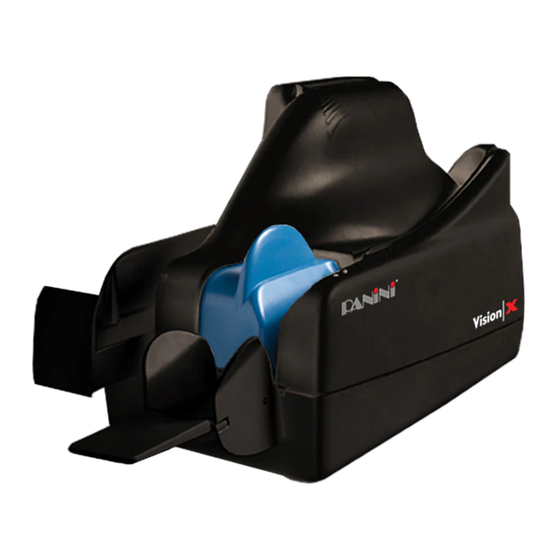
The Panini My Vision X is a new generation of check scanners. With a small footprint, sleek design and quiet operation, the Panini My Vision X fits perfectly in a small area such as a teller window, or on the back counter of bank branches. -
Page 9: Audience
• Dress safely. Do not wear loose clothing, long hair or jewelry that can become entangled in moving parts. • Do not allow anything to rest on the power cord. Do not locate the My Vision X where people may walk on the cord. -
Page 10: If The Machine Is Damaged
10:21 Pagina 10 1.3 If the Machine is Damaged Unplug the My Vision X from the wall outlet and refer servicing to qualified personnel under the following conditions: • If the power cord is damaged or frayed. • If liquid has been spilled into the product. -
Page 11: Learning About The Panini My Vision
The Panini My Vision X is a compact, easy-to-use and quiet scanner. The Panini My Vision X automatically scans the front and/or rear of checks while simultaneously capturing the Magnetic Ink Character Recognition (MICR) code line. An optional Ink-Jet endorser prints alphanumeric characters on the rear of items. - Page 12 1. Remove the Accessories box, the operator manual and the power cable out of the packaging. 2. Holding the packaging down with one hand, lift the My Vision X together with the packing materials making use of the plastic handle (Fig.3).
-
Page 13: External Parts Description
Panini My VisionX_07.06 6-10-2006 10:21 Pagina 13 2.2 External Parts Description This section describes the major components of the Panini My Vision X. The component names introduced here and shown in the figures are used throughout this manual. Inner Cover Pocket Extension... -
Page 14: Internal Parts Description
10 “U” Track Wall 11 Transport Rollers 12 Ink-Jet Cartridge Cradle 13 Front Image Camera 14 Rear Image Camera 15 Pocket sensor 16 Transport Belt 17 Interlock Board 18 Feeder Motor Fig.6 Page 14 OPERATOR MANUAL Learning about the Panini My Vision X... -
Page 15: Operating Your Panini My Vision
6-10-2006 10:21 Pagina 15 3. Operating your Panini My Vision X 3.1 Document Support Installation Insert the Feeder Extension in the slot uncovered by pushing back the Document Pressure Plate. Installation is correct if the Feeder Extension is at the same level of the entrance of the scanner platform. - Page 16 3.2 Extension Plate Installation The feeder extension is designed to support all documents anticipated to be processed by the My Vision X. Markets or applications that process a large number of long documents (longer than 8 inches) may find it necessary to apply the optional extension plate for better document support, reducing the risk of image skewing, MICR rejects, etc.
-
Page 17: Power Cables Connection
Fig.11 Fig.10 3. The My Vision X should be plugged into a dedicated electrical power outlet. The power supply will be 100-240 VAC (no power selection required), and the frequency 50/60 Hz. If you are not sure of the type of power available, consult your Service Representative or local power company. -
Page 18: Usb 2 Cable Connection
Connect the USB 2 cable to the USB 2.0 port located on the rear side of the scanner, then connect the other end of the cable to an available USB 2.0 port on the PC. USB 2 cable Fig.12 Page 18 OPERATOR MANUAL Operating your Panini My Vision X... -
Page 19: Hp C6602A Ink-Jet Cartridge Installation
Angle the front side of the cartridge downwards and face the two pins with the two holes in the cradle. Gently push down the rear side of the cartridge until it snaps in the plastic retainer. Ink-Jet cartridge HP C6602A Panini P/N: CA-00138-00 Plastic retainer Cartridge cradle Fig.13 Page 19 OPERATOR MANUAL Operating your Panini My Vision X... -
Page 20: Hp 51604A Rev.b Ink-Jet Cartridge Installation
Gently insert the Ink-Jet cartridge against the holder and pull up the plastic lever to lock the cartridge in place. Ink-Jet cartridge HP 51604A rev B PANINI P/N: BA-00037-01 Additional Plastic Lever Cartridge cradle Fig.14 Page 20 OPERATOR MANUAL Operating your Panini My Vision X... -
Page 21: Pocket Length Adjustment
Move the pocket extension left or right until a space of 5 mm (1/4”) is available between the leading edge of the document and the end of the pocket extension. 5mm (1/4’’) Fig.15 Page 21 OPERATOR MANUAL Operating your Panini My Vision X... -
Page 22: Getting Started
Note: An application must be started before you begin to process documents. When the application starts, the My Vision X turns on which is indicated by the green led in the outer cover. If it is your job to start the application, refer to the documentation supplied with the application by the vendor. -
Page 23: Status Lights
Blinking Jam on the transport track Fig.16 Note: There is no LED power indication upon connecting the My Vision X. LED status indicators only illuminate when the application connects to the My Vision X unit. Page 23 OPERATOR MANUAL... -
Page 24: How To Prepare And Load Checks
Panini My VisionX_07.06 6-10-2006 10:21 Pagina 24 4.2 How to Prepare and Load Checks Preparing Documents for Processing 1. Remove all rubber bands, staples, paper clips, dog ears, etc. from the documents. 2. Jogging the documents is strongly recommended. In any case, align the bottom edges by repeatedly tapping the bottom edge of the documents on a hard, flat surface, see Fig.17. - Page 25 Panini My VisionX_07.06 6-10-2006 10:21 Pagina 25 Feeding Documents You may feed documents one at a time or in batches of up to 30 by inserting the documents all the way into the feeder. (Fig.19). The documents must be inserted into the feeder so that the leading edge fits between the two black lines shown in Fig.20.
- Page 26 Panini My VisionX_07.06 6-10-2006 10:21 Pagina 26 Batches greater than 30 to 100 checks require the pressure plate 2mm (1/8’’) be pushed back before inserting checks into the feeder. To prevent misfeeding, do not insert more than 100 documents into the feeder. Leave at least 2 mm (1/8”) between the last document and the pressure plate in the maximum backwards position.
- Page 27 Panini My VisionX_07.06 6-10-2006 10:21 Pagina 27 The feeder is designed so that checks can be loaded continuously, while the scanner is processing. This can be done by inserting checks behind those already present in the feeder. Fig.22 Page 27...
- Page 28 Panini My VisionX_07.06 6-10-2006 10:21 Pagina 28 Removing Documents from Pocket Processed documents are sent to the exit pocket. For best result, follow these recommendations: • Remove the documents when the pocket is nearly full. Jams occur when the pocket is too full.
-
Page 29: Clearing Jams
Panini My VisionX_07.06 6-10-2006 10:21 Pagina 29 4.3 Clearing Jams When a jam occurs, the paper path must be cleared. To do this, first remove all the documents from the exit pocket and then free the track by pressing Eject in your application. - Page 30 Panini My VisionX_07.06 6-10-2006 10:21 Pagina 30 Fig.25 3. Grab the document with your fingers to remove it from the transport. (See Fig.25). Fig.26 4. After the jam is removed, install the inner cover by following the instructions below: a. Open the pocket extension.
- Page 31 Panini My VisionX_07.06 6-10-2006 10:21 Pagina 31 c. Push down the inner cover until it is back to its original position. Take care to ensure that the inner cover stays behind the scanner, which is indicated by a black area (see Fig.27).
- Page 32 Panini My VisionX_07.06 6-10-2006 10:21 Pagina 32 d. Check the exit pocket to ensure that the two plastic springs are aligned properly as shown in Fig.28. Fig.28 5. In the event that the outer cover has to be removed, first disconnect the USB and power cables and then lift the outer cover as shown in Fig.29.
- Page 33 Panini My VisionX_07.06 6-10-2006 10:21 Pagina 33 6. To remove the “U” track wall see Fig.30. Please follow the instructions listed in chapter 5.1.2. Fig.30 7. If the jam occurs in the image camera area, it is advisable to open the front image camera (see Fig.31) so that the document can easily be...
- Page 34 Panini My VisionX_07.06 6-10-2006 10:21 Pagina 34 8. Insert the outer cover by aligning the two shafts with the holes in the bottom cover of the unit (Fig.32). Insert the two teeth located on each side of the outer cover in the bottom cover and lock it (Fig.33 and 34).
-
Page 35: Maintenance
Panini My VisionX_07.06 6-10-2006 10:21 Pagina 35 5. Maintenance Warning: Before doing maintenance, remember to disconnect the USB 2 and power cables from the device. Note: The parts accessible to the operator for cleaning or jam removal are identifiable by green stickers. -
Page 36: Cleaning The Transport
Panini My VisionX_07.06 6-10-2006 10:21 Pagina 36 5.1 Cleaning the Transport Dust, lint and small particles can get into the track area. Clean this area as follows: 1. Remove the inner and outer covers by pulling up on the covers as illustrated below. - Page 37 Panini My VisionX_07.06 6-10-2006 10:21 Pagina 37 2. To remove the U-track, pull back on lever (A) away from unit (Fig.39). The Fig.40 shows how to pull the lever and remove the U-track. Fig.39 Fig.40 3. Inspect and clean the entire track area from beginning to end.
- Page 38 Panini My VisionX_07.06 6-10-2006 10:21 Pagina 38 6. To reinstall the U-track insert the two teeth “C” in the rail “D” (Fig.44), and align the U-track (Fig.41). Push back the U-track (Fig.45) until the lever “E” (Fig.41) locks the unit in place.
- Page 39 Panini My VisionX_07.06 6-10-2006 10:21 Pagina 39 Note: If the blotting pad housing assembly. (A) comes away from the U-track, insert the low mylar spring in the lateral slots (B) and the pad housing in the reference pins (C). Gently press down until the pad housing stops on the top of the U-Track wall.
-
Page 40: Cleaning The Contact Image Sensors
Panini My VisionX_07.06 6-10-2006 10:21 Pagina 40 5.2 Cleaning the Contact Image Sensors 1. Gently open the front image camera (Fig.48) and remove any debris and dust. 2. Clean the Contact Image Sensors with a soft, lint-free cloth dampened with Isopropyl Alcohol or with eye glass cleaner (Fig.49). -
Page 41: Cleaning The Hp C6602A Ink-Jet Cartridge
Panini My VisionX_07.06 6-10-2006 10:21 Pagina 41 5.3 Cleaning the HP C6602A Ink-Jet Cartridge Fibers, such as cotton or paper, dried ink plugs or crust, or excess ink puddles on the nozzle plate can obstruct ink droplets or cause ink droplets to deflect from the desired trajectory, resulting in a degraded print quality. -
Page 42: Cleaning The Hp 51604A Rev.b Ink-Jet Cartridge
Panini My VisionX_07.06 6-10-2006 10:21 Pagina 42 5.4 Cleaning the HP 51604A rev.B Ink-Jet cartridge Fibers, such as cotton or paper, dried ink plugs or crust, or excess ink puddles on the nozzle plate can obstruct ink droplets or cause ink droplets to deflect from the desired trajectory, resulting in a degraded print quality. - Page 43 Panini My VisionX_07.06 6-10-2006 10:21 Pagina 43 5.5 Cleaning the Photocell Detectors The six photocells (emitter and receiver) are identified with black circles in Fig.52 below. Using a container of canned air and nozzle, spray the sensors to remove any dust.
-
Page 44: Replacing The Feeder And Separator Rollers
Panini My VisionX_07.06 6-10-2006 10:21 Pagina 44 5.6 Replacing the Feeder and Separator Rollers After extended use it will be necessary to replace the Feeder and Separator Roller rings due to normal wear. 1. Open the inner and outer covers. - Page 45 Panini My VisionX_07.06 6-10-2006 10:21 Pagina 45 3. Install the new separator rings on the hubs by pressing down on the surface of the rings, making sure the rings are installed flat on their seats. The feeder ring must be rolled onto the black pulley.
-
Page 46: Cleaning The Reading Transport Belt
Panini My VisionX_07.06 6-10-2006 10:21 Pagina 46 5.7 Cleaning the Reading Transport Belt If an increase in the number of MICR (Magnetic Ink Characters Recognition) rejects is noticed, it may be necessary to clean the surface of the reading transport belt to remove extraneous magnetic ink or iron dust. -
Page 47: Install The External Covers
Panini My VisionX_07.06 6-10-2006 10:21 Pagina 47 5.8 Install the External Covers Install the inner cover following the instructions below: Fig.58 1. Open the pocket extension. 2. Insert the two reference shafts in the corresponding housings found in the inner cover (Fig.58). - Page 48 Panini My VisionX_07.06 6-10-2006 10:21 Pagina 48 The inner cover (grid) must be Scanner inserted behind the scanner (black) Inner cover Fig.60 4. Check the exit pocket to ensure that the two plastic springs are properly aligned as shown in Fig.60.
- Page 49 Panini My VisionX_07.06 6-10-2006 10:21 Pagina 49 5. Insert the outer cover by aligning the two shafts with the two holes in the bottom cover of the unit (Fig.61). Push the cover down. Fig.61 6. Insert the two teeth located on each side of the outer cover in the bottom cover and lock it see Fig.62 and 63.
-
Page 50: Specifications
Panini My VisionX_07.06 6-10-2006 10:21 Pagina 50 6. Specifications 6.1 Technical Specifications of the Panini My Vision X Various models processing up to 30 dpm, 60 dpm, or 90 dpm with a USB 2.0 interface PERFORMANCE AUTOMATIC DOCUMENT FEEDER 3 mode feeder:... - Page 51 Panini My VisionX_07.06 6-10-2006 10:21 Pagina 51 Panini Vision API running on: SOFTWARE TOOLS Windows 2000 SP3 and Windows XP SP1 or higher with USB2.0 or with USB1.1 at reduced performance Windows NT 4.0 SP6 with USB1.1 ICR Vision function for image snippet definition & download;...
-
Page 52: Technical Specifications Of The Pc
10:21 Pagina 52 6.2 Technical Specification of the PC Panini Vision API running on: Windows 2000 SP3 or Windows XP SP1 or higher with USB2.0 or USB1.1 port Windows NT 4.0 SP6 with USB1.1 30 dpm and 60 dpm Models... -
Page 53: My Vision X Sd Addendum
The SD scanner unit is designed for single document processing exclusively. All references to preparing and processing batches of multiple items in this section is not relevant to the SD version of the My Vision X. Inserting multiple items into the feeder of a SD scanner unit will cause multiple documents to be fed or document jams to occur. -
Page 54: My Vision X Agp Addendum
10:21 Pagina 54 8. My Vision X AGP Addendum This addendum provides specific product details related to the My Vision X AGP model. This information highlights product characteristics that vary from the information in the Operator Manual. AGP Packaging List ** Replaces section 2.1... - Page 55 • Open the rear cradle lever and remove the print cartridge • Use the Panini cleaning cloth (Panini P/N: GS-00020-00) or a wet lent free cloth (de-ionized water is best) wipe slowly across the long-axis with the print cartridge facing down (as shown). The damp cloth should draw ink from the cartridge flushing out the nozzles.
- Page 56 Panini My VisionX_07.06 6-10-2006 10:21 Pagina 56 Notes:...
Need help?
Do you have a question about the My Vision X and is the answer not in the manual?
Questions and answers