Mobotix T24 System Manual
Hide thumbs
Also See for T24:
- System manual (120 pages) ,
- Reset and reconfigure (8 pages) ,
- Quick manual (4 pages)
Table of Contents
Advertisement
Quick Links
Download this manual
See also:
Quick Manual
T24 System Manual
HD Super Panorama: From wall to wall without any blind spots
HiRes Video Innovations
The German company MOBOTIX AG is known as the leading pioneer in network camera technology and its
decentralized concept has made high-resolution video systems cost efficient.
MOBOTIX AG • D-67722 Langmeil • Tel: +49-6302-9816-103 • Fax: +49-6302-9816-190 • sales@mobotix.com
Part 1: System Overview And Installation
Installation and cabling
(for the installer)
Part 2: Start-Up And Configuration
Software and network
(for the system administrator)
180°
The HiRes Video Company
Advertisement
Table of Contents

Related Manuals for Mobotix T24


Summary of Contents for Mobotix T24
- Page 1 HD Super Panorama: From wall to wall without any blind spots HiRes Video Innovations The German company MOBOTIX AG is known as the leading pioneer in network camera technology and its decentralized concept has made high-resolution video systems cost efficient.
- Page 2 • For two-wire cables up to 500 m T24-DoorMaster (indoors) • Opens door, doorbell on/o • Status LEDs for door and messages • Backup power supply with battery • Connects to door opener and sensors © MOBOTIX AG • Security-Vision-Systems • Made in Germany www.mobotix.com • info@mobotix.com...
-
Page 3: Table Of Contents
/148 SYSTEM MANUAL PART 1 - SYSTEM OVERVIEW AND INSTALLATION This T24 System Manual Part 1 (system overview and installation) is complemented by T24 System Manual Part 2 (start-up and configuration). If you no longer have a manual at your disposal, you can download a PDF file from the MOBOTIX website (www.mobotix.com >... - Page 4 2.1.2 Without A T24-DoorMaster 2.1.3 With T24-Info2wire+ And T24-DoorMaster 2.1.4 Recommendation For Cabling 2.1.5 Installation Tip: Replacing An Existing Doorbell With The T24 Remote Stations And Network Connection 2.2.1 Notes On Cable Lengths And Power Supply 2.2.2 Direct Connection Of One Remote Station 2.2.3 Network Connection With Multiple Remote Stations...
- Page 5 2.9.4 IO Module And Terminal Connectors 2.9.5 Connections In The Door Station 2.9.6 Connecting, Securing And Removing Modules Notes Download the latest version of this manual as a PDF file from www.mobotix.com !"#$ &'("#)*+&"', ® (Support > Manuals). All rights reserved. MOBOTIX and MxEasy™...
- Page 6 IP Video Door Station, the recording of video and audio data may be subject to special constraints or may be prohibited. All users of MOBOTIX products are therefore requested to inform themselves of and comply with all currently applicable regulations.
- Page 7 /148 © MOBOTIX AG • Security-Vision-Systems • Made in Germany www.mobotix.com • info@mobotix.com...
-
Page 8: Foreword
Dear MOBOTIX customer, Congratulations on your decision to purchase an exceptionally versatile and innovative IP Video Door Station “made in Germany.” The T24 system contains a hemispheric door camera with a 3.1 megapixel color sensor (T24-CamCore) and captures the entire room 180°... - Page 9 /148 !"#$ 2$13#&+4 +5*'62 +" * )*0&)3) "7$#7 $- HD Super 180° Panorama HD 360° Full Image: Entire scene in one view © MOBOTIX AG • Security-Vision-Systems • Made in Germany www.mobotix.com • sales@mobotix.com...
-
Page 10: Hemispheric Ip Video Door Station
What Are The Specific Advantages Of A MOBOTIX IP Video Door Station? The new T24 IP Video Door Station from MOBOTIX o ers an innovative, powerful solution that is easy to install and takes a di erent approach to the solutions available on the market up to now. - Page 11 What Advantages Does MOBOTIX O er Over Other Video Door Stations? Thanks to its HiRes image quality, decentralized technology and a wide range of features, MOBOTIX o ers not only an outstanding door camera but also a professional security camera in a single device. MOBOTIX Hemispheric Video Technology was successfully introduced to the network video market =&25$4$ 7&$-...
-
Page 12: Allround View With No Blind Spots
/148 T24 System Manual Part 1: Allround View With No Blind Spots Hemispheric HiRes Camera Thanks to the fisheye lens with its 180° image angle, the camera records the entire entrance area without having to be mechanically panned or tilted – without any blind spots, from wall to Standard 90°... - Page 13 floor in front of the door, for example, even the often overlooked area underneath the door station. And the T24 does all of this using only its software – without the need for moving parts or motors. This camera is silent, discreet and unobtrusive.
-
Page 14: Overview Of Modules
(T24-KeypadRFID). A particular advantage of the T24 is the minimal amount of cabling involved – either a standard Ethernet cable (for example, CAT7) or existing bell wire is su cient to connect the door station to the network in the building and to supply it with power. - Page 15 /148 Hemispheric Door Camera With Allround View And No Blind Spots (T24-CamCore) With 3.1 megapixels and an internal memory, this hemispheric door camera records the entire entrance area. No blind spots from wall to wall and from floor to ceiling. The camera can record events automatically.
-
Page 16: Individual Components: Outdoors
T24-OPT-ETH: Securely connects the camera module with the mounted 8 wires of the network patch cable via RJ45 connector. Only for T24 versions without Mx2wire+. T24-OPT-IO: The board provides an additional 8 signal inputs and 3 signal outputs to connect external devices (doorbell, light, etc.). Modules 85$ 1*)$#* )";3<$ &2 *<2"... - Page 17 123 x 328 x 52 mm (W x H x D). The in-wall housing is securely connected with the subsurface or brick work. It can also be used to ensure easy installation in cavities. © MOBOTIX AG • Security-Vision-Systems • Made in Germany www.mobotix.com • sales@mobotix.com...
-
Page 18: Individual Components: Indoors
IEEE 802.3af standard. It is therefore possible to secure the power supply for distances up to 100 m (300 ft) using the network cable. As a result, the T24 IP Video Door Station can be supplied with PoE power via the adapter and connected directly to a Grandstream video telephone or to a computer (integrated crossover function). - Page 19 /148 T24: The Custom-Made IP Video Door Station The T24 product line is a modular system that can be adapted to any customer needs. This highly robust and weatherproof outdoor station (IP65, suitable for -30°C to +50°C / -22°F to +122°F) is available in four attractive colors: white, silver, dark gray, black and amber.
-
Page 20: Configuration Examples
(PW) (SV) (DG) (BL) (AM) © MOBOTIX AG • Security-Vision-Systems • Made in Germany www.mobotix.com • sales@mobotix.com... - Page 21 /148 © MOBOTIX AG • Security-Vision-Systems • Made in Germany www.mobotix.com • sales@mobotix.com...
-
Page 22: System Image
SYSTEM OVERVIEW: T24 IP VIDEO DOOR STATION What does a typical system look like and what components are included? This section describes the setup for a complete system with a video door station including a T24- DoorMaster, T24-KeypadRFID and T24-Info2wire+ info module with Mx2wire+ technology to connect the door station using existing two-wire cabling. - Page 23 • Two-way video communication, open door, turn light on/o • Operate camera (including image correction) • Monitor door status (open/closed/locked) • Recording and event search • Voice mailbox player © MOBOTIX AG • Security-Vision-Systems • Made in Germany www.mobotix.com • sales@mobotix.com...
-
Page 24: System Overview
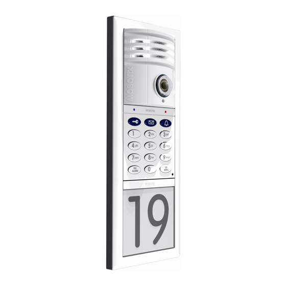
99 mm Integrated 4 GB MicroSD card Speaker LEDs Light button Door bell Lens Microphone MxBus connector Seal Mini USB (for future expansion modules) Network connection Bayonet catch © MOBOTIX AG • Security-Vision-Systems • Made in Germany www.mobotix.com • sales@mobotix.com... - Page 25 3 W; via PoE switch/MOBOTIX PoE adapter/Mx2wire+ Operating conditions IP65 (DIN EN 60529), -30°C to + 50°C (-22°F to +122°F) Interfaces MxBus, USB, Ethernet Dimensions (W x H) 99 mm x 99 mm © MOBOTIX AG • Security-Vision-Systems • Made in Germany www.mobotix.com • sales@mobotix.com...
-
Page 26: Ethernet Terminal Board T24-Opt-Eth
1.1.2 Ethernet Terminal Board T24-OPT-ETH The ethernet terminal board T24-OPT-ETH is used to connect the door station for the T24 versions without Mx2wire+ technology. It securely connects the camera module with the 8 connected wires of the network patch cable via RJ45 connector (for installation, see Chapter 2). - Page 27 The Ethernet terminal board is screwed on to the housing (on-wall or in-wall) behind the camera module. a<+$#'*+&7$<4A +5$ $0+$';$; +$#)&'*< /"*#; 89:?M[8?KM 1*' /$ 32$; +" 1"''$1+ $0+$#'*< ;$7 1$2A 2315 *2 * ;""#/$<< © MOBOTIX AG • Security-Vision-Systems • Made in Germany www.mobotix.com • sales@mobotix.com...
-
Page 28: Access Module T24-Keypadrfid
1*#;2 ("# ;""# ">$' '@ *'; 7"&1$ )*&</"0 *11$22 View with housing cover removed a;;&+&"'*< 1*#;2 Sealing plug Pa;) 'Rb2$#Q 1*' /$ "#;$#$; (#") !MNM8KO Seal IO terminal MxBus terminal © MOBOTIX AG • Security-Vision-Systems • Made in Germany www.mobotix.com • sales@mobotix.com... - Page 29 flexible Cable cross-section, min. 0.25 mm²/max. 0.5 mm² flexible, with wire-end sleeves without plastic sleeves Cable cross-section min. 24/max. 20 AWG/kcmil AWG according to UL/CUL min. 26/max. 20 © MOBOTIX AG • Security-Vision-Systems • Made in Germany www.mobotix.com • sales@mobotix.com...
-
Page 30: Info Module T24-Info
LED technology. 99 mm Info field can be labeled (behind cover) View with housing cover removed Sealing plug Seal MxBus terminal (power supply for the LED) © MOBOTIX AG • Security-Vision-Systems • Made in Germany www.mobotix.com • sales@mobotix.com... - Page 31 AWG/kcmil AWG according to UL/CUL min. 26/max. 20 Note On Labeling You will find some PDF templates, which you can print out yourself, on the MOBOTIX website (www.mobotix.com). © MOBOTIX AG • Security-Vision-Systems • Made in Germany www.mobotix.com • sales@mobotix.com...
-
Page 32: T24-Info2Wire+ (Info Module With Indoor Unit)
(using tweezers or small pliers) before mounting the module itself. LED illumination LED illumination deactivated activated © MOBOTIX AG • Security-Vision-Systems • Made in Germany www.mobotix.com • sales@mobotix.com... - Page 33 Dimensions (W x H) 99 mm x 99 mm Note On Labeling You will find some PDF templates, which you can print out yourself, on the MOBOTIX website (www.mobotix.com). Standard Two-Wire Cabling (Already Laid In Buildings) Analog Telephone Line Or Bell Wire •...
- Page 34 RJ45 network connection 48-57 V DC ["-$# 23>><4 -&+5 Two-wire connection (optional ["`U 2-&+15 "# (T24-Info2wire+ additional info module) :F?cX ^ C\A JGG )a power supply) P>"-$# 23>><4 3'&+Q © MOBOTIX AG • Security-Vision-Systems • Made in Germany www.mobotix.com • sales@mobotix.com...
- Page 35 80 mm x 80 mm x 38 mm (in-wall version), Dimensions (W x H x D) 80 mm x 80 mm x 45 mm (on-wall version) Max. Cable Lengths Of Usable Cable Types As Two-Wire Cable Of A T24 Door Station Cable type Cable thickness Max.
-
Page 36: Housing And Module Frames
IO module (3x) Mounting points for cable binders (8x, marked yellow) Cable guide (6x) Mounting points for module frames (8x, marked green) Mounting points for seal © MOBOTIX AG • Security-Vision-Systems • Made in Germany www.mobotix.com • sales@mobotix.com... - Page 37 /148 Outdoor Station 131 mm 26 mm 44 mm 76 mm © MOBOTIX AG • Security-Vision-Systems • Made in Germany www.mobotix.com • sales@mobotix.com...
- Page 38 EEX 0 E9Y )) for module frames C"3/<$ 5"32 '@, EEX 0 9EF )) 8#&><$ 5"32&'@, Mounting points for seal EEX 0 IEF )) Retaining wings for cavity installation (4x) © MOBOTIX AG • Security-Vision-Systems • Made in Germany www.mobotix.com • sales@mobotix.com...
- Page 39 /148 Outdoor Station 131 mm [$#)&22&/<$ -*<< +5&16'$22 ("# 1*7&+4 &'2+*<<*+&"', )&'. X ))R)*0. 9X )) Xe9X )) 69 mm 97 mm © MOBOTIX AG • Security-Vision-Systems • Made in Germany www.mobotix.com • sales@mobotix.com...
- Page 40 Installation of module Connection of anti-theft protection Activation of anti-theft protection Key to release the modules from the frame (press upwards; only possible after anti-theft protection has been deactivated) © MOBOTIX AG • Security-Vision-Systems • Made in Germany www.mobotix.com • sales@mobotix.com...
- Page 41 With integrated Ethernet terminal On-wall or T24-KeypadRFID, anti-theft board or in-wall T24-Info/T24-Info2wire+ protection IO module housing f `+5$#'$+ +$#)&'*< /"*#; 89:?M[8?`8B &2 '"+ #$V3&#$; -5$' 32&'@ !09-&#$U +$15'"<"@4 © MOBOTIX AG • Security-Vision-Systems • Made in Germany www.mobotix.com • sales@mobotix.com...
-
Page 42: T24-Doormaster
/148 T24 System Manual Part 1: System Overview T24-DoorMaster The T24 may be coupled with the T24-DoorMaster with internal access code memory, making it impossible to open the door by forcibly removing the system and bypassing the connecting cable. 80 mm... - Page 43 An electrically-operated standard door opener (6 to 12 V AC, min. nominal resistance 10 ohm, no support for closed-circuit current function) can be connected directly to the T24-DoorMaster and powered by its integrated battery pack. It is not necessary to connect an additional power supply unit.
-
Page 44: Remote Stations
MOBOTIX recommends the GXV3140 from Grandstream as a remote video station for the T24 door station. This modern IP video telephone is based on the world standard in telephony, VoIP/SIP with H.264, and provides a large color LCD display with excellent image quality. - Page 45 In principle, other IP video telephones (with H.264 and G.711) can also be used as a T24 remote station. Due to the technical specifications of a particular device (display size, audio functions, etc.), however, it cannot be guaranteed that all T24 remote station functions of the Grandstream GXV3140 are available.
-
Page 46: Mxeasy Video Management Software
T24 System Manual Part 1: System Overview 1.3.2 MxEasy Video Management Software MOBOTIX provides the MxEasy software free of charge to configure and operate the T24 IP Video Door Station with a network-enabled desktop or notebook computer. In principle, there is no need for a computer to handle configuration or operation when there is a simple... - Page 47 Optional HTTPS encryption (using certificates generated by the camera or created by the administrator) helps you to prevent unauthorized users from accessing MxEasy. © MOBOTIX AG • Security-Vision-Systems • Made in Germany www.mobotix.com • sales@mobotix.com...
-
Page 48: Accessories
IEEE 802.3af standard. It is therefore possible to secure the power supply for distances up to 100 m (300 ft) using the network cable. As a result, the T24 IP Video Door Station can be supplied with PoE power via the adapter and connected directly to a remote station (integrated crossover function). -
Page 49: T24-Opt-Io (Extended Terminal Boards)
/148 Accessories 1.4.2 T24-OPT-IO (Extended Terminal Boards) In addition to the ethernet terminal board (T24-OPT-ETH), MOBOTIX o ers an IO module (T24-OPT-IO) with extended connection options for the door station (e.g., doorbell buttons, light, garage door opener, etc.). The board provides 8 switch inputs and 3 switch outputs. The network cable and the camera module T24-CamCore are connected in the same manner as the Ethernet terminal board. -
Page 50: Additional Devices For Poe Power Supply
Internet (such as the Fritz!Box). In this case and if only one T24 door station needs to be supplied with power, it is su cient to purchase one PoE injector. -
Page 51: Additional Video Remote Stations
Accessories 1.4.4 Additional Video Remote Stations Thanks to the use of network technology, the T24 is not bound to just one expensive, manufacturer-dependent remote station. It can be connected to any suitable VoIP video phone (video: H.264, sound: G.711) in the world. In addition to supporting the two-way video communication feature with video and sound, these devices support additional features such as door/light control, image search, quick recording and PTZ functions. -
Page 52: Installation
Overview: Connection And Wiring Diagrams The following diagrams are an overview of the wiring plans that will allow you to connect the T24 IP Video Door Station as intended. Please refer closely to the configuration that best suits your particular needs. - Page 53 6$4>*; "# '(" )";3<$Q !";3<$2 *#$ 1"''$1+$; 7&* +5$ <"">$;?+5#"3@5A +-"?-&#$ !0N32 1*/<$ +5*+ +#*'2($#2 ;*+* *'; >"-$# 2&)3<+*'$"32<4 85$ )";3<$ +$#)&'*< ;$2&@'*+&"'2 *#$ *<2" <"1*+$; ;&#$1+<4 "' +5$ )";3<$ © MOBOTIX AG • Security-Vision-Systems • Made in Germany www.mobotix.com • sales@mobotix.com...
-
Page 54: Without A T24-Doormaster
T24 System Manual Part 1: Installation 2.1.2 Without A T24-DoorMaster When a T24-DoorMaster is not used, the electric door opener or Mediator, including the door and door lock sensors, are connected directly to the keypad. In addition, an external 12 V voltage is applied to the door mechanism/Mediator and bridged over to the keypad. - Page 55 7&* +5$ <"">$;?+5#"3@5A +-"?-&#$ !0N32 1*/<$ +5*+ +#*'2($#2 ;*+* *'; >"-$# 2&)3<+*'$"32<4 P1*/<$ '1<3;$; &' >*16*@ '@Q 85$ )";3<$ +$#)&'*< ;$2&@'*+&"'2 1*' /$ ("3'; ;&#$1+<4 "' +5$ )";3<$ © MOBOTIX AG • Security-Vision-Systems • Made in Germany www.mobotix.com • sales@mobotix.com...
-
Page 56: With T24-Info2Wire+ And T24-Doormaster
T24 System Manual Part 1: Installation 2.1.3 With T24-Info2wire+ And T24-DoorMaster To be able to use a bell wire already laid in the building to connect the T24 door station to the network and supply it with power, the T24 version with Mx2wire+ technology is required. - Page 57 '1<3;$; &' >*16*@ '@Q a' `+5$#'$+ >*+15 1*/<$ &2 32$; +" 1"''$1+ +5$ !09-&#$U &'(" )";3<$ +" +5$ 1*)$#* 85$ )";3<$ +$#)&'*< ;$2&@'*+&"'2 *#$ *<2" <"1*+$; ;&#$1+<4 "' +5$ )";3<$ © MOBOTIX AG • Security-Vision-Systems • Made in Germany www.mobotix.com • sales@mobotix.com...
-
Page 58: Recommendation For Cabling
7 cable is designed for 10 Gbit Ethernet (max. future compatibility) • Max. cable length: 100 m Two wires from the door station to the T24-DoorMaster for the MxBus connector • Recommendation: YSTY (telephone) solid wire, core diameter 0.6 to 0.8 mm •... - Page 59 (e.g., for lamp) YSTY 0.8 mm (e.g., external light) Max. length: depends on the manufacturer PoE switch (remote station connection) Cat 5 installation cable or higher Max. length: 100 m © MOBOTIX AG • Security-Vision-Systems • Made in Germany www.mobotix.com • sales@mobotix.com...
-
Page 60: Installation Tip: Replacing An Existing Doorbell With The T24
Unscrew and remove the doorbell. Connect the wire pair to the T24-Info2wire+ info module (T24 is mounted directly above the cable). This wire pair is conducted directly to the electrical cabinet, from where it is connected to the power supply and remote stations via the T24-Info2wire+ indoor unit. - Page 61 Overview: Connection And Wiring Diagrams Step 2: Install And Connect The T24-DoorMaster Install the T24-DoorMaster in a in-wall socket on the wall behind the door station (inside the building). Besides the in-wall socket, only two holes are required for the entire cabling.
-
Page 62: Remote Stations And Network Connection
A MOBOTIX PoE adapter (MX-NPA-PoE) or other similar, high-quality PoE product conforming to IEEE 802.3af is required to supply the T24 with power (PoE switch). A PoE+ switch (IEEE 802.3at) or a 48 V power supply unit can be used to supply power to the T24 version with Mx2wire+ technology. -
Page 63: Network Connection With Multiple Remote Stations
MxEasy or VoIP videophones) in an existing network (for example, via an Internet box), MOBOTIX again recommends using a MOBOTIX PoE adapter (MX-NPA-PoE) or a switch with multiple ports to supply power to the door station. Connect the devices as shown in... - Page 64 For a door station with integrated Mx2wire+ technology, an external voltage source (48 V DC) - connected via two wires directly to one of the two T24-Info2wire+ units (info module or indoor unit) - can also be used to supply power via the network cable.
- Page 65 /148 Remote Stations And Network Connection Connecting Multiple T24 Door Stations In general, a (PoE) switch can be used to connect several T24 door stations to the same remote stations. However, only one T24 can be connected to a T24-DoorMaster.
-
Page 66: Mounting The Frame And Housing
T24-DoorMaster, remote stations and power supplies that are installed inside a building. Please note that only the T24 camera, keypad and info module are suitable for outdoor installation (IP65, -30°C to +50°C/-22°F to +122°F). The modules will only be weatherproof if they have been installed correctly using matching MOBOTIX housings and frames. - Page 67 The height from the ground to the upper edge of the frame should be at least 1.60 m. 1.60 m Unlike conventional door cameras, the T24 CamCore with its 180° image angle is also able to record visitors when they are NOT standing directly in front of the lens. This means that the door station can be mounted quite flexibly, which is particularly useful with...
-
Page 68: Inserting All The Cables
&'2+*<<*+&"' &' * -*<<j &+ )32+ /$ #$)"7$; *'; cavity housing, you should additionally seal the cable guides +5$' >"2&+&"'$; *@* ' with silicone. -5$' >#$>*#&'@ +5$ 1*/<$2 Pierce required guide holes © MOBOTIX AG • Security-Vision-Systems • Made in Germany www.mobotix.com • sales@mobotix.com... - Page 69 • Make sure su cient cable reserves are provided • Hint: If longer cable reserves are required, you can mount an additional in-wall socket underneath the on-wall housing (see the dashed line in the figure above). © MOBOTIX AG • Security-Vision-Systems • Made in Germany www.mobotix.com • sales@mobotix.com...
-
Page 70: Attaching The Housing
C"3/<$ 5"32 '@, EEX 0 9EF )) 8#&><$ 5"32&'@, EEX 0 IEF )) [$#)&22&/<$ -*<< +5 16'$22 ) '. X ))R)*0. 9X )) Retaining wings for cavity installation 117 mm © MOBOTIX AG • Security-Vision-Systems • Made in Germany Xe9X )) www.mobotix.com • sales@mobotix.com... - Page 71 After you have secured the in-wall housing, you can easily remove the protective cardboard by pushing through the pre-punched opening and simply pulling out the cardboard. Pierce opening hole and pull through cardboard © MOBOTIX AG • Security-Vision-Systems • Made in Germany www.mobotix.com • sales@mobotix.com...
-
Page 72: Cabling In The On-Wall Housing
T24 System Manual Part 1: Installation 2.3.4 Cabling In The On-Wall Housing To prevent cables from being damaged when you mount the frame or the T24 modules, make sure that the cables are routed correctly. Please refer to the example cabling shown in the figure below. - Page 73 /148 Mounting The Frame And Housing The T24 housing (on-wall/in-wall) provides su cient space for cable reserves (see the blue dashed line in the figure). The red areas are ‘o -limits areas’. No cables should be placed in this area (risk of damage to cables when module is mounted).
-
Page 74: Mounting The Terminal Board And Fitting The Network Cable
Screw the board into the housing (flattened side is at the bottom). The terminal board must be placed behind the camera module. This step is not necessary for the T24 version with Mx2wire+ technology (two-wire cable replaces Ethernet cable), as an Ethernet terminal board is not required. -
Page 75: Sticking The Seal In Place
D+ 16 +5$ 2$*< +" +5$ &''$# (#*)$ *2 25"-' &' +5$ ]@3#$ In-Wall And Cavity Housing D+ 16 +5$ 2$*< +" +5$ &''$# (#*)$ *2 25"-' &' +5$ ]@3#$ © MOBOTIX AG • Security-Vision-Systems • Made in Germany www.mobotix.com • sales@mobotix.com... -
Page 76: Attaching The Frame And Connecting The Anti-Theft Protection
T24 System Manual Part 1: Installation 2.3.7 Attaching The Frame And Connecting The Anti-Theft Protection Before the T24 modules can be clicked into the frame, you must screw the frame onto the housing (recommendation: cross slot PH 2x100) and lay the black anti-theft protection cable to the inside of the building according to your selected connection option, for example, to the T24-DoorMaster (you may also need to extend the cable). - Page 77 T24-DoorMaster (directly or extend with the two individual wire connectors) Insert wire (not stripped) (1) and press down cutting clamp with pliers (2) Note slot for key © MOBOTIX AG • Security-Vision-Systems • Made in Germany www.mobotix.com • sales@mobotix.com...
-
Page 78: Mechanical Anti-Theft Protection Lock
Important: After the installation, check the wiring (see Section 2.8.1) and only then activate the anti-theft protection lock. Retaining tabs Red rotary button © MOBOTIX AG • Security-Vision-Systems • Made in Germany www.mobotix.com • sales@mobotix.com... - Page 79 Turn the red rotary button so that the arrow points to the ‘opened lock’ symbol. K' +5&2 >"2&+&"'A 4"3 1*' 32$ +5$ 2>$1&*< 6$4 *<"'$ +" #$<$*2$ +5$ )";3<$2 (#") +5$ (#*)$ © MOBOTIX AG • Security-Vision-Systems • Made in Germany www.mobotix.com • sales@mobotix.com...
-
Page 80: Installing The T24 Modules
2.4.1 Installing The Camera Module T24-CamCore Standard Network Connection The Ethernet terminal board is used to connect the door station for the T24 version without Mx2wire+ technology. It connects the short, pre-installed camera patch cable with the eight split-out wires of the network installation cable (for installation, see Section 2.2.5). -
Page 81: Installing The T24 Modules
In this case, repeat the last steps, making sure that no cable or foreign object in the housing is preventing the module from properly clicking into place. © MOBOTIX AG • Security-Vision-Systems • Made in Germany www.mobotix.com • sales@mobotix.com... - Page 82 T24 System Manual Part 1: Installation Network Connection Via Mx2wire+ Technology An Ethernet terminal board is not required for the T24 door station with Mx2wire+ technology. Instead, the camera module is connected to the T24-Info2wire+ info module via a MOBOTIX patch cable.
- Page 83 In this case, repeat the last steps, making sure that no cable or foreign object in the housing is preventing the module from properly clicking into place. © MOBOTIX AG • Security-Vision-Systems • Made in Germany www.mobotix.com • sales@mobotix.com...
-
Page 84: Installing The T24-Keypadrfid
2.4.2 Installing The T24-KeypadRFID Please pay attention to the di erent system wiring configurations that apply (described in Section 2.1), depending on whether or not the T24-DoorMaster and external devices such as a light are used. 1. Ensure that the seal is fitted to the keypad. - Page 85 • Blue wire to MX - terminal *'; ? !0N32 -&#$2 Note If the info module is connected to the MxBus connector of the door camera T24- CamCore, the two MxBus cables of the T24-DoorMaster can be connected to the keypad instead.
- Page 86 MX + MX - MX + MX - IN 1+ IN 1- Door opener/power relay IN 2+ IN 2- Power supply OUT A e.g. 12 V AC OUT B © MOBOTIX AG • Security-Vision-Systems • Made in Germany www.mobotix.com • sales@mobotix.com...
- Page 87 Caution Do not activate the anti-theft protection lock until you have checked the wiring (see Section 2.8.1). Also test the functionality of the anti-theft protection (see Section 2.4.6). © MOBOTIX AG • Security-Vision-Systems • Made in Germany www.mobotix.com • sales@mobotix.com...
-
Page 88: Installing The Info Module T24-Info
T24 System Manual Part 1: Installation 2.4.3 Installing The Info Module T24-Info The info field in the info module of the T24 door station without Mx2wire+ technology is equipped with permanent LED backlighting supplied via MxBus. 1. Ensure that the seal is fitted to the info module. - Page 89 In this case, repeat the last steps, making sure that no cable or foreign object in the housing is preventing the module from properly clicking into place. © MOBOTIX AG • Security-Vision-Systems • Made in Germany www.mobotix.com • sales@mobotix.com...
-
Page 90: Installing The Info Module T24-Info2Wire
4. Connect the two-wire cable, which leads to the separate 89:?K'("9-&#$U ';""# 3'&+ P("# '2+*<<*+&"'A T24-Info2wire+ unit in the building, to the board. 2$$ D$1+&"' 9.JQ • First wire to Data 1 terminal • Second wire to Data 2 terminal ©... - Page 91 In this case, repeat Click the last steps, making sure that no cable or foreign object in the housing is preventing the module from properly clicking into place. © MOBOTIX AG • Security-Vision-Systems • Made in Germany www.mobotix.com • sales@mobotix.com...
-
Page 92: Labeling The Info Modules
You will find a PDF template on the MOBOTIX website to help you create your own label. Simply add your personal data to the template and print it onto a sheet of A4 paper. - Page 93 Here are a few examples of doorbell labels that were created using the PDF file template. a;"/$ a1#"/*+ L$*;$#, ;"-'<"*; (#") To open the file requires Adobe Acrobat Reader (free). ---.*;"/$.1") © MOBOTIX AG • Security-Vision-Systems • Made in Germany www.mobotix.com • sales@mobotix.com...
-
Page 94: Removing And Exchanging Modules
Hold at the same time until the blue LED flashes 2. Switching o anti-theft protection when there is no T24-DoorMaster: Connect the two cables of the anti-theft protection to the 12 V power supply of the electric door opener via a switch. Anti-theft protection is deactivated for as long as the voltage is applied (switch on). - Page 95 /148 Installing The T24 Modules 3. Removing the modules: Insert the special MOBOTIX key provided into the split opening on the module frame (bottom left or bottom right, depending on how it has been mounted) and release the modules from 85$ 2>$1&*<...
-
Page 96: Installing The T24-Doormaster
(open, closed, closed and locked). The T24-DoorMaster, with its speaker that can be switched o , also functions as a doorbell. It furthermore allows the door to be opened using a button and controls the anti-theft protection in the T24 housing. - Page 97 MxBus (MX -) Supported Door Opener Versions A standard door opener operated with 6 to 12 V AC can be connected directly to the T24- 85$ 89:?C""#!*2+$# )32+ /$ 1"']@3#$; DoorMaster and powered by its integrated battery pack. There is no need to connect an ("# +5$ 2$<$1+$;...
-
Page 98: Connection Diagrams For Door Opener Versions
Door opener -&+5 >< $#2Q OUT 2+ Version 2: Power Supply From External Power Supply Unit (Internal Relay Function) The T24-DoorMaster's integrated relay function switches a maximum external voltage of 24 V (SELV, max. 1 A). T24-DoorMaster 85$ 89:?C""#!*2+$# 5*2 *' &'+$@#*+$;... - Page 99 Version 3: Self-Locking Mediator Door Lock Including UPS Via Battery Pack In this connection option, the T24-DoorMaster's battery pack powers the system in the event of a power failure and allows the door to be opened without a key. In this case however, anti-theft protection must be controlled using an additional switch (to be ordered separately).
-
Page 100: Mounting Instructions
The anti-theft protection connection cables pre-fitted to the frame of the outdoor 89:?C""#!*2+$# *'; station do not need to be extended if the T24-DoorMaster is mounted on the same wall ;""# 2+*+&"', cG ) behind the outdoor station (next to the entrance door). - Page 101 flush with the wall, or if the T24-DoorMaster could easily be pulled out together with the in-wall socket. The in-wall socket used must be flush with the wall.
- Page 102 T24 System Manual Part 1: Installation Preparing The Cavity Socket (Cavity Wall) The T24-DoorMaster can be mounted to a cavity wall (for example, plasterboard up to a thickness of 35 mm) using either the supplied cavity socket or an existing socket. Push the B '+, b2$ * 1*7&+4...
-
Page 103: Installation Using Cavity Or In-Wall Socket
(B). The red LED indicates that the battery is low. 3. Screw on the MxBus cable (coming from the T24 L$)"7$ *>>#"0&)*+$<4 door station): c )) "( &'23<*+&"' (#") *<<... - Page 104 Electrical systems and equipment may only be set up, changed and maintained by a qualified electrician or under the management and supervision of a qualified electrician in accordance with electrotechnical regulations. © MOBOTIX AG • Security-Vision-Systems • Made in Germany www.mobotix.com • sales@mobotix.com...
- Page 105 first 12 hours. This takes place automatically via the PoE- 1*##&$; "3+ *(+$# +5$ #$; powered T24 door station using the MxBus two-wire cable. During this time, the electric d`C 5*2 @"'$ "3+ P*(+$# door opening function should not be used (except for a short functional test). This will *>>#"0 )*+$<4 Ec )&'3+$2Q...
-
Page 106: Installing The Indoor Unit T24-Info2Wire
Network Connection And Power Supply (Data And Power) The T24-Info2wire+ indoor unit has an RJ45 port and is connected by patch cable to a switch or router, and thus also to the local network and the remote stations. In order for Mx2wire+ to power the T24, a voltage source is required. - Page 107 A further advantage of Mx2wire+ is that it allows the range of a connection to be extended considerably using a two-wire cable up to 500 m long (a T24 connection using a network cable is limited to 100 m). For detailed technical information on the T24 version with Mx2wire+ technology, see Section 1.1.5.
-
Page 108: Mounting Instructions
In addition to an on-wall installation using the supplied surface-mounted socket, you can also choose to install the T24-Info2wire+ indoor unit using a standard in-wall socket or a cavity socket (for wood or plasterboard, for example). Included in the delivery is a cavity socket of very high quality with soft rubber gaskets on the rear that need to be punctured by the two wires that feed in. -
Page 109: Installation Using Cavity Or In-Wall Socket
2. Screw the two-wire cable to terminals 1 and 2: The cable does not necessarily need to be attached to the terminal with the same number on both T24-Info2wire+ units. The device continues to function if connectors 1 and 2 are swapped. - Page 110 6. Insert the panel: Hook the front panel onto the frame, as shown in the figure, and then press it down. 7. Screw the panel on tightly: Secure the front panel using the panel's stainless steel screw. © MOBOTIX AG • Security-Vision-Systems • Made in Germany www.mobotix.com • sales@mobotix.com...
-
Page 111: Installation With Surface-Mounted Socket
Use the 8-wire plug for multi-wire cables. You only require two of these wires for T24-Info2wire+. The other two ="# 1*/<$2 -&+5 * ceX )) g plugs with only one opening are ideally suited to insulated, two-wire cables of varying thickness. - Page 112 (3'1+&"' &( 1"''$1+"#2 cable does not necessarily need to be attached to the E *'; 9 *#$ 2-*>>$; terminal with the same number on both T24-Info2wire+ units. The device continues to function if connectors 1 and 2 are swapped. Connectors 3 and 4 are only assigned if an external voltage source (48 V DC) is used.
-
Page 113: Function Of Mx2Wire+ Status Leds
(is connected) Note The two status LEDs (orange, green) in the outdoor station's T24-Info2wire+ info module are only active for test purposes for the first 15 minutes after the power supply has been established. After the LEDs have gone out, they can be reactivated by interrupting the power supply for a short time. -
Page 114: Connecting External Devices To The Door Station
Connection is either via the MOBOTIX IO module (accessory: T24-OPT-IO) or the keypad. The T24 camera software is used to configure the switching of external devices and can be accessed via a standard web browser such as Internet Explorer. For additional information on this topic, see Part 2 of the System Manual. - Page 115 Module switches c PIR module/motion sensor Module switches c Bell button 4 Bell button 3 Bell switches c (full-wave) floor call switches ERT (half-wave) Bell button 2 Bell button 1 © MOBOTIX AG • Security-Vision-Systems • Made in Germany www.mobotix.com • sales@mobotix.com...
- Page 116 Electrical systems and equipment may only be set up, changed and maintained by a qualified electrician or under the management and supervision of a qualified electrician in accordance with electrotechnical regulations. © MOBOTIX AG • Security-Vision-Systems • Made in Germany www.mobotix.com • sales@mobotix.com...
- Page 117 12 V AC MX - MX + eLi/c Auth/S2 Connect 2nd to 4th doorbell buttons to 7.1 to 7.4 (similar to 7.1) 1st doorbell button © MOBOTIX AG • Security-Vision-Systems • Made in Germany www.mobotix.com • sales@mobotix.com...
-
Page 118: Using The Keypad Signal Outputs
T24 System Manual Part 1: Installation 2.7.2 Using The Keypad Signal Outputs If the T24 door station is used with the T24-DoorMaster and a standard door opener, all the keypad connectors apart from the MxBus connector remain unused (see Section 2.5.2, Version 1). - Page 119 1st doorbell button IN 1+ IN 1- IN 2+ Connect 2nd doorbell button to IN 2+ and IN 2- (similar to 1st doorbell button) IN 2- OUT A OUT B © MOBOTIX AG • Security-Vision-Systems • Made in Germany www.mobotix.com • sales@mobotix.com...
-
Page 120: Finishing The Installation
flash green and blue Notes The blinking of the green LED on the keypad and T24-DoorMaster indicates that data is communicated between the individual modules via Mx-Bus but the data communication is still unencrypted. After the system is started up (see Part 2 of the System Manual), the green LED lights up continuously (MxBus data communication is encrypted). - Page 121 The modules can only be removed now after deactivating the anti-theft protection. Before operating the door station, the batteries in the T24-DoorMaster must be fully charged (maximum charging time: 12 hours). Finish the installation with Section 2.8.2. that follows.
-
Page 122: Configuring The T24-Doormaster
/148 T24 System Manual Part 1: Installation 2.8.2 Configuring The T24-DoorMaster Before using the T24-DoorMaster, it is essential to configure the signal output option to be used (see Section 2.5.2). Three Options Are Available Option 1: Power Supply From T24-DoorMaster Battery (Self-Powered) D$<(?>"-$#$;... - Page 123 /148 Finishing The Installation The signal output option is set on the T24-DoorMaster in three steps as part of system startup. Step 1: Press both buttons at the same time for 5 seconds (until double beep) You are now in administration mode (red LED turns o shortly every 3 seconds).
-
Page 124: Installation In The Siedle Vario System
When used together with the expanded IO terminal board T24-OPT-IO, the hemispheric camera module T24-Cam-Core of the T24 IP Video Door Station can also be integrated into a Siedle Vario system to work with the Siedle modules described here. Siedle products (modules, frames, network devices and so on) cannot be ordered from MOBOTIX. - Page 125 Dummy module to cover empty slots, or placeholder for future expansions. 99 x 99 mm (W x H). Note Siedle Vario modules can also generally be mounted in the MOBOTIX T24 frame. © MOBOTIX AG • Security-Vision-Systems • Made in Germany...
- Page 126 Frame dimensions (in mm) for one to four modules =#*)$ ;&)$'2&"'2 &' )) vertically (right), or up to three modules each in a grid horizontally and vertically (left). © MOBOTIX AG • Security-Vision-Systems • Made in Germany www.mobotix.com • sales@mobotix.com...
- Page 127 /148 Installation In The Siedle Vario System © MOBOTIX AG • Security-Vision-Systems • Made in Germany www.mobotix.com • sales@mobotix.com...
-
Page 128: Determining The Installation Position
1.60 m (5 ft 3 in). Depending on the frame size and orientation, the camera module T24-CamCore must always be placed in the top left position in the Siedle frame. -
Page 129: Preparing Network And Power Connections
Recommendation For Cabling As a specification for cable line A (network), MOBOTIX recommends using a category 5 \*+ X 1*/<$ &2 (Cat 5) Ethernet installation cable or higher. For cable lines B, C and D, we recommend ;$2&@'$;... -
Page 130: Io Module And Terminal Connectors
2.9.4 IO Module And Terminal Connectors MOBOTIX IO Module T24-OPT-IO The central connection unit for the door station is available from MOBOTIX as an accessory and is required in the Siedle Vario system: • Bridge circuit from Ethernet installation cable to camera patch cable •... - Page 131 The figures show the correct final position of the connector terminals and IO module for both vertical and horizontal mounting of the door station. Connecting The Network Cable To The IO Module See Section 2.3.5. © MOBOTIX AG • Security-Vision-Systems • Made in Germany www.mobotix.com • sales@mobotix.com...
-
Page 132: Connections In The Door Station
The b signal is not always switched to the terminal marked as b on the Siedle terminal connectors. For modules for which the internal light is active, the iLi signal must be connected to terminal b. © MOBOTIX AG • Security-Vision-Systems • Made in Germany www.mobotix.com • sales@mobotix.com... - Page 133 Connection for both modules is identical: Connect module terminal bv to b; connect module terminals cv and S1 to c; connect module terminal S2 to IO module Auth/S2. Board Module Auth/S2 © MOBOTIX AG • Security-Vision-Systems • Made in Germany www.mobotix.com • sales@mobotix.com...
- Page 134 Module Siedle Info Module For switchable internal module lighting (iLi), connect module terminal c to c; connect K'(" module terminal b to IO module iLi. !";3<$ Board Module © MOBOTIX AG • Security-Vision-Systems • Made in Germany www.mobotix.com • sales@mobotix.com...
- Page 135 IO module (isolated output): connect relay input A1 to b; signal connect IO module eLi/c to c (control voltage); connect relay input A2 to IO module eLi. eLi/c Board Relay Transformer/ Relay signal © MOBOTIX AG • Security-Vision-Systems • Made in Germany www.mobotix.com • sales@mobotix.com...
- Page 136 7.1, 7.2, 7.3 or 7.4. Door Opener Connect the electromagnetic door-switch opener to IO module Do; connect second Board Module connector to c. Door opener © MOBOTIX AG • Security-Vision-Systems • Made in Germany www.mobotix.com • sales@mobotix.com...
- Page 137 (DSC 602-0) in the electrical cabinet. Anti-theft protection can only be activated or deactivated using this controller. Installation instructions are included in the Siedle Anti-Theft Protection package. © MOBOTIX AG • Security-Vision-Systems • Made in Germany www.mobotix.com • sales@mobotix.com...
-
Page 138: Connecting, Securing And Removing Modules
3. Mount the camera module: Place the camera module onto the installation frame from above and snap into place. © MOBOTIX AG • Security-Vision-Systems • Made in Germany www.mobotix.com • sales@mobotix.com... - Page 139 Siedle installation frame. Insert the key into the small opening between the modules and release the modules from the installation frame by pushing the key in. © MOBOTIX AG • Security-Vision-Systems • Made in Germany www.mobotix.com • sales@mobotix.com...
- Page 140 DNS server and gateway), as opposed to static IP addresses on the individual network devices. Abbreviation for Domain Name Service. Allows the domain names of servers on the Internet (for example, www.mobotix.com) to be linked (”resolved”) to their corresponding IP addresses (for example, 212.89.150.84). Door Opener The door opener (also known as e-opener, electric door opener) is installed complementary to the door lock.
- Page 141 IP addresses may change at any time. This service provides a convenient method to access your MOBOTIX cameras from home or work if the camera Internet connection is not through a router that assigns a fixed IP address, but instead over a DSL connection with a dynamically-assigned IP address from the provider.
- Page 142 Abbreviation for Light Emitting Diode; an electronic semiconductor component built into MOBOTIX cameras and add-on modules that emits light when a current flows through the component in the correct direction. The unit for measuring the quantity of light.
- Page 143 16 cameras/door stations. MxPEG Method developed by MOBOTIX to compress and store image and video data with low network load and high image quality. The MxPEG ActiveX control element allows video and audio data from MOBOTIX cameras to be displayed in other applications (including Internet Explorer).
- Page 144 Claims are only possible when the product is used in accordance with its intended use and there is no evidence of misuse. The technical specifications and information described in the T24 System Manual must be observed. Otherwise, the manufacturer is released from their product liability in accordance with the German Product Liability Act.
- Page 145 HTML pages or files for the client (browser) is known as a web server. (Signal) Inputs and Outputs Using the digital inputs and outputs on the T24, any device that can switch between an open and closed circuit can be connected.
- Page 146 These devices usually operate using a battery. UPS is installed on the power lines of devices and systems in order to protect them in the event of a power failure. © MOBOTIX AG • Security-Vision-Systems • Made in Germany www.mobotix.com • sales@mobotix.com...
- Page 147 A wireless LAN that transfers data over the mobile radio network. The end user is wirelessly connected to the network, while data transfer across the network’s main structure usually remains cable-based. © MOBOTIX AG • Security-Vision-Systems • Made in Germany www.mobotix.com • sales@mobotix.com...
- Page 148 /148 T24 System Manual Part 1: Declarations Of Conformity T24M Hemispheric Camera C$1<*#*+&"' M( \"'("#)&+4 ---.)"/"+&0.1") Z D3>>"#+ Z !$;&* d&/#*#4 Z \$#+&]1*+$2 © MOBOTIX AG • Security-Vision-Systems • Made in Germany www.mobotix.com • sales@mobotix.com...
- Page 149 Tax O ce: Worms-Kirchheimbolanden http://www.mobotix.com VAT ID: sales@mobotix.com DE202203501 You can fi nd the latest version of this document at www.mobotix.com under Support. Technical specifi cations subject to change without notice! © MOBOTIX AG • Security-Vision-Systems • Made in Germany www.mobotix.com • sales@mobotix.com...
- Page 150 HD Super Panorama: From wall to wall without any blind spots HiRes Video Innovations The German company MOBOTIX AG is known as the leading pioneer in network camera technology and its decentralized concept has made high-resolution video systems cost efficient.
Need help?
Do you have a question about the T24 and is the answer not in the manual?
Questions and answers