Advertisement
Quick Links
COM-IDS(RS)-BM1-EN
PROGRAMMING CABLE ADS-USB (REQUIRED)
notice
The manufacturer will accept no responsability for any electrical
damage resulting from improper installation of this product, be that either
damage to the vehicle itself or to the installed device. This device must be in-
stalled by a certified technician. Please review the Installation Guide carefully
before beginning any work.
Automotive Data Solutions Inc. © 2013
instaLL guiDe
Document numbeR
11866
Revision Date
20130723
FiRmwaRe
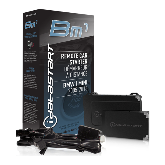
COM-IDS(RS)-BM1
haRDwaRe
ADS-BM1
accessoRies
COMPATIBLE RF-KIT (OPTIONAL)
DRONE MOBILE DR-2000 (OPTIONAL)
FT-D100 (OPTIONAL)
beFoRe instaLLation
1- Connect module to computer
2- Login to Weblink account
3- Flash firmware to module (module is not preloaded with firmware)
4- Use accessories accordingly (accessories are sold separately)
compustar.idatalink.com
Advertisement

Subscribe to Our Youtube Channel
Summary of Contents for idatastart COM-IDS(RS)-BM1-EN
- Page 1 Revision Date 20130723 FiRmwaRe COM-IDS(RS)-BM1 haRDwaRe ADS-BM1 accessoRies PROGRAMMING CABLE ADS-USB (REQUIRED) COMPATIBLE RF-KIT (OPTIONAL) DRONE MOBILE DR-2000 (OPTIONAL) FT-D100 (OPTIONAL) notice beFoRe instaLLation The manufacturer will accept no responsability for any electrical damage resulting from improper installation of this product, be that either 1- Connect module to computer damage to the vehicle itself or to the installed device.
- Page 2 ** If equipped with an electric E-brake and it is activated, vehicle will shudown when a door is opened during RS sequence. *** If equipped with the Confort Access System, the door handles will not be functional during RS sequence. Automotive Data Solutions Inc. © 2013 COM-IDS(RS)-BM1-EN compustar.idatalink.com...
- Page 3 T-HARNESS 2 EXPANSION PACK XP LED 1 XP LED 2 STICKER 2 EXPANSION CABLE ACCESSORIES (SOLD SEPARATELY) PROGRAMMING CABLE (REQUIRED) RF KIT (OPTIONAL) COMPATIBLE MODELS ONLY TELEMATICS DEVICE (OPTIONAL) COMPATIBLE MODELS ONLY Automotive Data Solutions Inc. © 2013 COM-IDS(RS)-BM1-EN compustar.idatalink.com...
- Page 4 Before installing this product, consult our Install Video Gallery and watch: • Vehicle Disassembly Procedure videos • Module Connection Procedures videos • Module Programming Procedures videos Simply visit our forum and register at http://www.12voltdata.com/forum/viewtopic.php?f=340&t=9683&sid=a61772b486e4584ad6f058b171ffa425 Automotive Data Solutions Inc. © 2013 COM-IDS(RS)-BM1-EN compustar.idatalink.com...
- Page 5 Connect the C connector to the module, as Module installation procedure completed. programming cable and fl ash the module with shown in STEP 2 of the WIRING DIAGRAM. the latest fi rmware. (F port) Automotive Data Solutions Inc. © 2013 COM-IDS(RS)-BM1-EN compustar.idatalink.com...
- Page 6 07 GRAY/WHITE - HOOD STATUS (-) INPUT WITH AN OEM HOOD SWITCH, INSTALL AN AFTERMARKET HOOD SWITCH 08 GRAY/BLACK (NC) BLACK 4 PIN - RF CABLE RF KIT BLUE 4 PIN - TELEMATIC CABLE TELEMATIC Automotive Data Solutions Inc. © 2013 COM-IDS(RS)-BM1-EN compustar.idatalink.com...
- Page 7 Insert keyfob 1 into keyport. LED 1 will turn solid RED. Within 10 seconds, LED 1 will fl ash GREEN Insert keyfob 1 into keyport. rapidly. Automotive Data Solutions Inc. © 2013 COM-IDS(RS)-BM1-EN compustar.idatalink.com...
- Page 8 NO: The module does NOT detect the brake pedal signal from the vehicle communication network. Press LOCK button three times [3x] rapidly on the OEM keyfob to shut down vehicle and call technical support. Apply parking brake. Exit vehicle. Automotive Data Solutions Inc. © 2013 COM-IDS(RS)-BM1-EN compustar.idatalink.com...
- Page 9 NO: For Z4, X5, X6: The module does NOT detect the parking brake signal correctly from the vehicle communication network. Call technical support. NO: For 1, 3, 5, 6, X1: Go to step 23. Press and release brake pedal. Push vehicle start button once [1x] to shut down the vehicle. Installation checklist completed. Automotive Data Solutions Inc. © 2013 COM-IDS(RS)-BM1-EN compustar.idatalink.com...
- Page 10 1.5 second, then will fl ash once [1x] to indicate that the valet mode is ON or twice [2x] to indicate that the valet mode is OFF. Turn ignition to STOP position. STOP ACC STOP ON START ENGINE START STOP Automotive Data Solutions Inc. © 2013 COM-IDS(RS)-BM1-EN compustar.idatalink.com...
- Page 11 Parking Light will fl ash once [1x]. Turn ignition to STOP position. STOP ACC STOP ON START ENGINE START STOP Time restriction. Complete next step within 5 Remove keyfob from keyport. seconds from previous step. Automotive Data Solutions Inc. © 2013 COM-IDS(RS)-BM1-EN compustar.idatalink.com...
- Page 12 Failure to exit the Module Navigation will drain button as many times as the menu number Navigation and redo the Module Navigation vehicle battery. indicates. LED 1 will fl ash GREEN an equal Procedure. amount of times continuously. Automotive Data Solutions Inc. © 2013 COM-IDS(RS)-BM1-EN compustar.idatalink.com...
- Page 13 05 SEC 08 SEC 10 SEC WAIT TO START DELAY 15 SEC 20 SEC 25 SEC 30 SEC 10-15 N/A 02-07 Technical Support only *Vehicle will shutdown when a door is opened. Automotive Data Solutions Inc. © 2013 COM-IDS(RS)-BM1-EN compustar.idatalink.com...
- Page 14 The parking lights will fl ash four [4x] times, then will fl ash Check engine warning light is ON. [Y] number times to indicate an error code. See table. Low fuel warning light is ON. CAN communication failure during RS sequence. Automotive Data Solutions Inc. © 2013 COM-IDS(RS)-BM1-EN compustar.idatalink.com...
- Page 15 Module not programmed. Waiting for more vehicle information. Flashing GREEN False ground when running status from remote starter. WITH IGNITION OFF Solid GREEN then OFF Reset in progress. Module at rest and ready for a remote start sequence. Automotive Data Solutions Inc. © 2013 COM-IDS(RS)-BM1-EN compustar.idatalink.com...
- Page 16 BLACK 20-PIN connector. DTC or a CHECK ENGINE error message. Wait, LED 1 will flash RED. RELEASE programming button. LED 1 will turn RED for 2 seconds. Module RESET completed. Automotive Data Solutions Inc. © 2013 COM-IDS(RS)-BM1-EN compustar.idatalink.com...


![Remote Starter idatastart COM-IDS(RS)-BZ3-[CMBMXA0]-EN Install Manual](https://static-data2.manualslib.com/product-images/403/3038576/60x60/idatastart-com-ids-rs-bz3-cmbmxa0-en-remote-starter.jpg)
![Remote Starter idatastart OEM-IDS(RS)-BM1-[ADS-BM1]-EN Install Manual](http://static.manualslib.com/public/img/no_image_60x60.svg)


Need help?
Do you have a question about the COM-IDS(RS)-BM1-EN and is the answer not in the manual?
Questions and answers