Advertisement
Quick Links
U.S. Patent No. 8,856,780
Automotive Data Solutions Inc. © 2015
PRoDuct guiDe
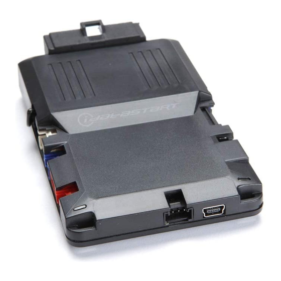
iDatastart HC
Document numbeR
Revision Date
20151022
notice
The manufacturer will accept no responsability for any electrical damage resulting from
improper installation of this product, be that either damage to the vehicle itself or to the
installed device. This device must be installed by a certified technician. Please review the
Installation Guide carefully before beginning any work.
www.idatalink.com
Advertisement

Related Manuals for idatastart HC


![Remote Starter idatastart OEM-IDS(RS)-BM1-[ADS-BM1]-EN Install Manual](http://static.manualslib.com/public/img/no_image_60x60.svg)


Summary of Contents for idatastart HC
- Page 1 PRoDuct guiDe iDatastart HC Document numbeR Revision Date 20151022 notice The manufacturer will accept no responsability for any electrical damage resulting from improper installation of this product, be that either damage to the vehicle itself or to the installed device. This device must be installed by a certified technician. Please review the Installation Guide carefully before beginning any work.
-
Page 2: Getting Started
• 20151022 WeLcome tabLe oF contents Box Contents Congratulations on the purchase of your iDataStart HC solution. You are now a few simple steps away from enjoying your new remote starter unit with Module Pinout enhanced features. Tach Programming Procedure... - Page 3 Page 3 of 13 BOX CONTENTS - 1 OF 1 • 20151022 BOX CONTENTS HC2 - HC2352AC HC MODULE 2-WAY REMOTE - TR2350AC M1 - 8 PIN BLACK AUTOMATIC TRANSMISSION CUT LOOP M2 - 12 PIN BLACK M5 - 6 PIN BLUE...
- Page 4 Page 4 of 13 MODULE PINOUT - 1 OF 1 • 20151022 HC MODULE 01 ORANGE - ACCESSORY (+) 01 ORANGE - ACCESSORY (+) 02 RED - POWER (30A) 02 RED - POWER (30A) 03 PURPLE - STARTER (+) 03 PURPLE - STARTER (+) 04 PINK/WHITE - PROG.
- Page 5 2.5 seconds.) Wait, LED 2 will fl ash GREEN. (See the Module Diagnostics page) Release the brake pedal. Module Programming Procedure completed. U.S. Patent No. 8,856,780 Automotive Data Solutions Inc. © 2015 iDatastart HC www.idatalink.com...
- Page 6 6 to 9. _________________________________ Press once [1x] on the LOCK button of each remote. The antenna’s leds will fl ash BLUE once [1x] for each successful pairing. U.S. Patent No. 8,856,780 Automotive Data Solutions Inc. © 2015 iDatastart HC www.idatalink.com...
- Page 7 Press and release the BRAKE pedal three times [3x]. Parking Light will fl ash once [1x] then will fl ash twice [2x]. Set ignition to OFF position. ON START ENGINE START STOP U.S. Patent No. 8,856,780 Automotive Data Solutions Inc. © 2015 iDatastart HC www.idatalink.com...
- Page 8 4 PIN BLACK CABLE MODULE WEBLINK PORT MOBILE DEVICE PORT OBDII CONNECTOR TELEMATIC KIT (accessory sold separately) (NC) MODULE TELEMATIC BLUE PORT *For SmartStart, use the module’s RED Telematic port. U.S. Patent No. 8,856,780 Automotive Data Solutions Inc. © 2015 iDatastart HC www.idatalink.com...
- Page 9 MODULE WHITE BLACK RF PORT BLUE CABLE DECODER BLACK CABLE ANTENNA RF KIT (included with the HC1 & HC2) MODULE RF PORT 4 PIN BLACK CABLE ANTENNA U.S. Patent No. 8,856,780 Automotive Data Solutions Inc. © 2015 iDatastart HC www.idatalink.com...
- Page 10 Set inputs for Auto by fi rmware/Data/Analog MENU 8 – Output Confi gurations Set outputs for Auto by fi rmware/Data/Analog Programming options are avaible through Weblink and Weblink Mobile only. U.S. Patent No. 8,856,780 Automotive Data Solutions Inc. © 2015 iDatastart HC www.idatalink.com...
-
Page 11: Test Module
False ground when running status from remote starter. WITH IGNITION OFF Solid GREEN then OFF Reset in progress. Module at rest and ready for a remote start sequence. U.S. Patent No. 8,856,780 Automotive Data Solutions Inc. © 2015 iDatastart HC www.idatalink.com... - Page 12 CAN communication failure during RS sequence. RS not synchronized. Start vehicle with OEM key for 15 sec before trying a new RS sequence. Takeover is not allowed. Shutdown error, board overheat protection. U.S. Patent No. 8,856,780 Automotive Data Solutions Inc. © 2015 iDatastart HC www.idatalink.com...
- Page 13 DTC or a CHECK ENGINE error message. 8-pin connector and the M4 BLACK 20-pin connector. Wait, LED 1 will flash RED. RELEASE programming button. LED 1 will turn RED for 2 seconds. U.S. Patent No. 8,856,780 Automotive Data Solutions Inc. © 2015 iDatastart HC www.idatalink.com...
Need help?
Do you have a question about the HC and is the answer not in the manual?
Questions and answers