Table of Contents
Advertisement
Advertisement
Table of Contents

Subscribe to Our Youtube Channel
Related Manuals for Lionel O72 Wye Remote Switch Fastrack


Summary of Contents for Lionel O72 Wye Remote Switch Fastrack
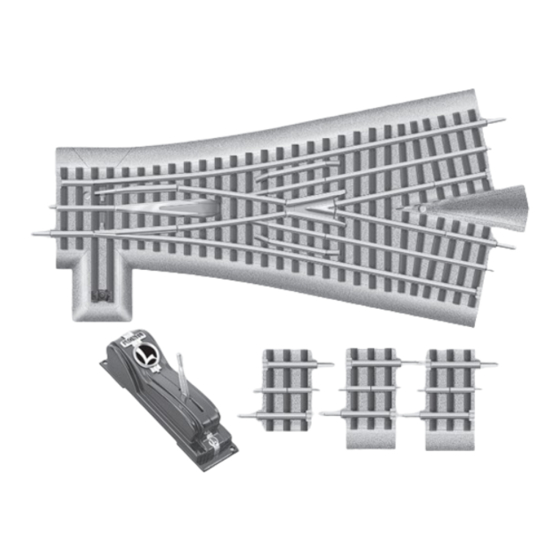
- Page 1 71-2047-250 8/08 Lionel O72 Wye Remote Switch Owner’s Manual...
-
Page 2: Table Of Contents
Operating the switch in the TrainMaster Command Control environment 9-10 Servicing the lamps Limited Warranty/Lionel Service The following Lionel marks may be used throughout this instruction manual and are protected under law. All rights reserved. Lionel , TrainMaster , Odyssey... -
Page 3: Joining The Fastrack Track Sections
Joining the FasTrack track sections asTrack track sections join together easily. With interlocking roadbed sections and Rail tab large rail tabs, the track fits together securely so you always get good electrical contact. Refer to Figure 1 to see how to join the track sections. -
Page 4: Operating The Switch
Operating the switch ou may operate the switch using the controller or the illuminated switch lamp on the roadbed. Refer to Figure 3. To operate the switch using the controller, power up the track, then pull the lever to the opposite position. Gently press the lever past the end of its path. The lights inside the controller will change colors to designate the change in switch positions. -
Page 5: Changing The Switch Stand Location
Changing the switch stand location ou may choose to position the switch stand either inside or outside the loop of track. Follow these steps and refer to Figure 4 to change the location of the switch stand. 1. Remove the two screws that secure the small roadbed section to the switch and lift away the roadbed section. -
Page 6: Routing The Controller Cable
Routing the controller cable ou may choose to route the controller cable through the notch on either side of the roadbed. As illustrated in Figure 5, simply bend the tabs to free the cable and reroute the wire. Once the cable is in place, bend down the tabs to hold the wire in the channel. Remove the notch section of roadbed and route the wire through the notch. -
Page 7: Mounting The Controllers
Mounting the controllers f you have multiple switches and controllers, you may choose to snap the interlocking controller bases together and mount them to your control panel using screws. To join the controller bases, snap the bases together on a flat surface as illustrated in Figure 6. Drive screws through the holes in the controller bases to secure the controllers to your layout. -
Page 8: Powering The Switch Through A Separate Power Supply
Powering the switch through a separate power supply ou may choose to connect the switch to a separate power supply to operate the switch when track power is off or set to a low voltage. This is most beneficial to those operating in the conventional environment. -
Page 9: Connecting The Controller
Connecting the controller he four controller wires are attached to the terminals on the underside of the switch. The controller wires were attached at the factory. The connections are as follows: green wire to THRU, black wire to GND, red wire to OUT, and yellow wire to RSC LIGHTS. Operating the switch in the TrainMaster Command Control environ- ment ou may choose to operate the switch in the TrainMaster Command Control environment... -
Page 10: Operating The Switch In The Trainmaster Command Control Environment
Operating the switch in the TrainMaster Command Control environ- ment (continued) SC-2 connections The SC-2 is capable of controlling up to five remote switches at a time. Wire the switches to the terminals on the back of the SC-2 unit as illustrated in Figure 10. Do not connect your FasTrack switch to the #1 terminal on the SC-2. -
Page 11: Servicing The Lamps
(LEDs). The LEDs are expected to last for the life of the switch and are not user serviceable. See your authorized Lionel Service Center if your LEDs require service. - Page 12 (requires proof of purchase from the Lionel Authorized Retailer* it was originally purchased). Any products on which warranty service is sought must be sent freight or postage prepaid (Lionel will refuse any package when postage is due). Transportation and shipping charges are not covered as part of this warranty.
Need help?
Do you have a question about the O72 Wye Remote Switch Fastrack and is the answer not in the manual?
Questions and answers