Advertisement
Advertisement

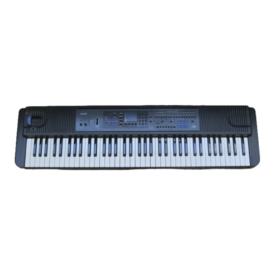
Summary of Contents for Casio WK-1500
- Page 1 WK-1500 PITCH BEND WK-1500 GM SOUND KEYBOARD...
-
Page 2: Table Of Contents
Tempo: Adjustable (216 levels, = 40 to 255) Chords: 3 types (CASIO Chords, Fingered, Full-Range Chords) Pads: Rhythm, bass, Chord 1, Chord 2, Chord 3 (adjustable on/off, tone, volume, pan, effect send, fine tune, coarse tune, expression settings) Magical presets:... - Page 3 MIDI: 16-timbre multi-timbre receive (General MIDI Level 1) 12 cm diameter × 2 (output: 5 W + 5 W) Built-in speakers: Input/Output Jacks Power supply: 12 V DC Headphones: Stereo standard jack Output impedance: 100 Ω Output jacks: Output voltage 2.5 V (RMS) MAX Assignable Jack: Standard jack (sustain, sostenuto, soft, rhythm start/stop) MIDI terminals:...
-
Page 4: Block Diagram
BLOCK DIAGRAM LED driver LED driver 7-seg. LED IC371 Q104 ~ Q111 LEDs MIDI BA612 La ~ Lg, Lp KO1 ~ KO3 LS0 ~ KO Signal KO0 ~ Generator IC102 Buttons TC74HC174AF LSI14 Keyboard KI1 ~ KI5 HD6433294A19F Power Switch POWER FI0 ~ FI7 Reset IC... -
Page 5: Circuit Description
CIRCUIT DESCRIPTION KEY MATRIX E1 (1) F1 (1) F#1 (1) G1 (1) G#1 (1) A1 (1) A#1 (1) E1 (2) F1 (2) F#1 (2) G1 (2) G#1 (2) A1 (2) A#1 (2) B1 (1) C2 (1) C#2 (1) D2 (1) D#2 (1) E2 (1) F2 (1) - Page 6 NOMENCLATURE OF KEYS G#1 A#1 C#2 D#2 F#2 G#2 A#2 C#3 D#3 F#3 G#3 A#3 C#4 D#4 F#4 G#4 A#4 C#5 D#5 F#5 G#5 A#5 C#6 D#6 F#6 G#6 A#6 C#7 D#7 G1 A1 B1 C2 D2 E2 F2 G2 A2 B2 C3 D3 E3 F3 G3 A3 B3 C4 D4 E4 F4 G4 A4 B4 C5 D5 E5 F5 G5 A5 B5 C6 D6 E6 F6 G6 A6 B6 C7 D7 E7 F7 G7 BUTTON MATRIX CH8/ CH10/...
- Page 7 CPU (LSI14: HD6433294A19F) The 16-bit CPU contains a 32k-bit ROM, a 1k-bit RAM, seven 8-bit I/O ports, an A/D convertor and MIDIl interfaces. The CPU accesses to the working storage RAM, the DSP and the key touch LSI. The CPU interprets MIDI message using the working storage RAM.
- Page 8 Pin No. Terminal I n / O u t Function 1 ~ 8 CD0 ~ CD7 In/Out Data bus 9, 10 CE1, TRSB — Not used GND7 Ground (0 V) source CK16 Terminal for 24.576 MHz clock check point VCC6 +5 V source Clock input.
- Page 9 Pin No. Terminal I n / O u t Function EOEB Read enable signal output for the effect RAM VCC7 +5 V source ECEB Chip select signal output for the effect RAM 113 ~ 117 ED11 ~ ED15 — Not used VCC4 +5 V source GND4...
- Page 10 DAC (IC11: UPD6376GS) The DAC receives 16-bit serial data output from the DSP. The data contains digital sound data of the melody, chord, bass, and percussion for the right and left channels. The DAC converts the data into analog waveforms by each channel and output them separately. The following table shows the pin functions of IC11.
- Page 11 The following table shows the pin functions of LSI16. Pin No. Terminal I n / O u t Function REQB Not used. FI8 ~ FI10, 2, 3, 60 ~ 63 Not used. Connected to +5 V. SI8 ~ SI10 +5 V source CRDB Read enable signal input CWRB...
- Page 12 POWER AMPLIFIER (IC201: LA4620) The power amplifier is a two-channel amplifier with standby switch. Boot11 IN11+ Input Pre-drive Power OUT11 Amp. Amp. Amp. IN11– – RL Short PoGND1 Protector – IN12– Input Pre-drive Power OUT12 Amp. Amp. Amp. Boot12 Terminal Pop Noise Ripple Protection...
-
Page 13: Major Waveforms
MAJOR WAVEFORMS A 1 µs A 1 µs A . 1 s A . 200 ms ˜ ˜ CH1: 5 V CH2: 5 V CH1: 5 V CH2: 5 V CH1: 5 V CH2: 5 V CH3: 5 V CH1: 20 mV CH2: 20 mV 1 Voltage VDD 3 Power ON signal PSW... -
Page 14: Printed Circuit Boards
PRINTED CIRCUIT BOARDS MAIN PCB JCM717-MA1M C146 R124 R123 R122 C103 LSI11 R121 R120 R119 R118 C141 R117 R116 C142 R115 R114 R113 FB51 C153 C152 R112 FB52 R111 R110 R109 MR17 R108 C143 R107 LSI15 R106 MR16 R105 R104 IC12 LSI14 R103... -
Page 15: Schematic Diagrams
SCHEMATIC DIAGRAMS MAIN PCB JCM717-MA1M 6 7 8 — 15 —... - Page 16 SUB PCB KDM717-MA2M — 16 —...
- Page 17 CONSOLE PCBs KDM717-CN1M/CN2/CN3/CN4 — 17 —...
- Page 18 KEYBOARD PCBs JCM762T-KY1M/KY2M/KY3 — 18 —...
-
Page 19: Exploded View
EXPLODED VIEW... -
Page 20: Parts List
PARTS LIST WK-1500 Notes: Prices and specifications are subject to change with- out prior notice. As for spare parts order and supply, refer to the "GUIDEBOOK for Spare parts Supply", published seperately. The numbers in item column correspond to the same... - Page 21 Item Code No. Parts Name Specification Main PCB 6925 3130 Main PCB ass'y, M717-MA1M M140443*1 LSI2 2012 4536 LSI, ROM MX23C2410MC-12CA51 LSI3 2012 0777 LSI, RAM LC33832M-70-TLM LSI7 2012 4298 LSI, UPD65611GB-019-3BA LSI11 2012 1316 LSI, DSP HG51B155FD-1 LSI14 2012 4550 LSI, CPU HD6433294A19F LSI15 2012 4291 LSI, RAM...
- Page 22 Item Code No. Parts Name Specification 2765 1141 Volume RK1631110-50KB 6925 3570 Knob, Bender M31488-3 Keyboard unit 6922 2720 White key set, LT M312118*1 6923 7900 White key set, LT76R M340231*1 6923 7910 White key set, LT76L M340230*1 6922 2740 Black key set, LT10P M111726-1 6923 7930 Black key set, LT-76-3P M111726-3...
- Page 23 MA0900761A Sep, 1996...


Need help?
Do you have a question about the WK-1500 and is the answer not in the manual?
Questions and answers