
Related Manuals for Polaroid M402b


Summary of Contents for Polaroid M402b
- Page 1 Repair Manual M402b MiniPortrait Camera April 2000 Technical Publications TEL: 1.781.386.5309...
-
Page 2: Table Of Contents
402b MiniPortrait Camera Repair Manual Table of Contents Table of Contents 1. Overview ........................ Description ......................Features ......................Specifications ..................... 2. Parts Replacement ....................Required Tools and Equipment ................ Front Cover Assembly ..................Removal ......................Installation ......................Shutter Assembly ....................Removal ...................... - Page 3 Installation ......................3. Calibration ......................F8 Adjustment ....................... 4. Parts Catalog ......................M402b MiniPortrait Camera (Parts List 1) ............Front Cover Assembly (Parts List 2) ..............Shutter plate Assembly (Parts List 3)..............Camera Body Assembly (Parts List 4) .............. Viewfinder Assembly (Parts List 5) ..............
-
Page 4: Overview
Overview 1. Overview Description This section of the Repair Manual gives an overview of the M402b MiniPortrait Camera . It provides the necessary information pertaining to features and specifications for the camera. Note: For detailed information pertaining to setting up and using the camera, refer to the User Guide. -
Page 5: Camera Features
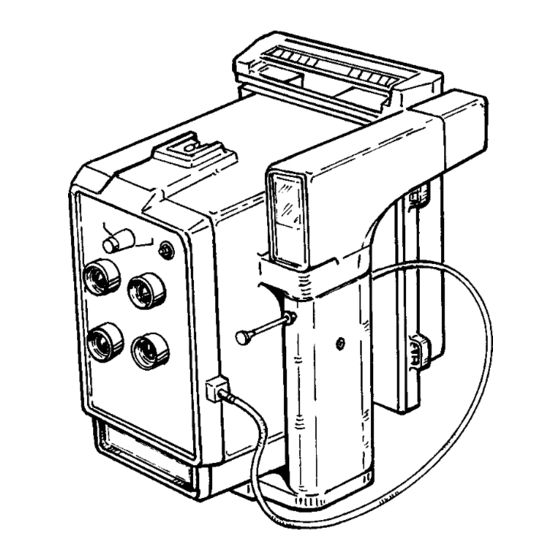
M402b MiniPortrait Camera Repair Manual Overview Camera Back Hot Shoe Aperture Knob Viewfinder Shutter Cocking Lever Not shown Camera Back Interface Plate X-sync Connector Lens Shutter Release Cable Shutter Button Tripod Mount (Not Shown) Figure 1-2. Camera features Table 1-1. Camera features (cont'd) - Page 6 Camera Back The camera uses Polaroid 3 1/4 x 4 1/4 peel-apart pack films to produce color or black and white photos. An adapted CB-103 camera back comes with the camera.
- Page 7 M402b MiniPortrait Camera Repair Manual Overview Table 1-1. Camera features (cont'd) Features Description Viewfinder Used to frame the subject. Place the subject the appropriate distance from the shutter and then look through the viewfinder to frame the subject. Once the subject is framed, press the shutter button or the shutter release cable.
-
Page 8: Specifications
15.25 cm x 21.5 cm x 17.75 cm Film All Polaroid 3 1/4 x 4 1/4 color pack films, including Polaroid Studio 125, Studio Polaroid, T669, and PC100. All Polaroid 3 1/4 x 4 1/4 B&W films including T664 and T667. -
Page 9: Parts Replacement
M402b MiniPortrait Camera Repair Manual Disassembly/Assembly 2. Disassembly/Assembly This section of the Repair Manual describes the camera's disassembly procedures. CAUTION Care should be taken throughout all disassembly and reassembly procedures never to smudge or soil the lenses. Required Tools and Equipment •... -
Page 10: Installation
M402b MiniPortrait Camera Repair Manual Disassembly/Assembly 5. Gently lift off the front cover being careful not to disturb the alignment of the shutter plates. Note: If the shutter and the diaphragm plates are misaligned during the removal of the front cover, refer to the Shutter and Diaphragm Plate assembly/disassembly procedure to properly realign (see page 24). - Page 11 M402b MiniPortrait Camera Repair Manual Disassembly/Assembly 3. Using a Phillips head screw driver, install and tighten the six (6) screws that secure the front cover and the shutter plate assembly to the camera body. CAUTION When installing the front cover make sure: •...
-
Page 12: Shutter Assembly
M402b MiniPortrait Camera Repair Manual Disassembly/Assembly Shutter Plate Assembl y (Figure 2-2) Removal 1. Remove the front cover assembly (Figure 2-1). 2. Gently lift off the shutter plate assembly being careful not to disturb the alignment of the shutter plates. - Page 13 M402b MiniPortrait Camera Repair Manual Disassembly/Assembly 2. Gently position the shutter plate assembly onto the camera body being careful not to disturb the alignment of the shutter plates. Note: If the shutter and the diaphragm plates are misaligned during the installation of the shutter plate assembly, refer to the Shutter and Diaphragm Plate assembly/disassembly procedure to properly realign (see page 24).
-
Page 14: Camera Back Assembly
M402b MiniPortrait Camera Repair Manual Disassembly/Assembly Camera Back Assembly (Figure 2-3) Removal 1. Unlatch the camera back latches. 2. Lift off the camera back assembly. Camera Back Camera Back Latch Camera Body Figure 2-3. Removing camera back Installation 1. Place the camera back assembly onto the camera back interface plate making sure that it is properly aligned. -
Page 15: Camera Back Interface Plate
M402b MiniPortrait Camera Repair Manual Disassembly/Assembly Camera Back Interface Plate (Figure 2-4) Removal 1. Remove the camera back (Figure 2-3). 2. Using a Phillips head screw driver, remove the twelve (12) flat head screws that secure the camera back interface plate to the camera body. -
Page 16: Viewfinder Assembly
M402b MiniPortrait Camera Repair Manual Disassembly/Assembly Viewfinder Assembly (Figure 2-5) Removal 1. Unscrew the cable release from the shutter button. 2. Remove the front viewfinder bezel. 3. Remove the rubber eyepiece. 4. Using a Phillips head screw driver, remove the two (2) screws that secure the rear of the outside viewfinder hand grip to the rear of the inside viewfinder hand grip. -
Page 17: Installation
M402b MiniPortrait Camera Repair Manual Disassembly/Assembly 9. Using a Phillips head screw driver, remove the two (2) screws that secure the bottom of the inside viewfinder hand grip to the hand grip base. 10. Using a Phillips head screw driver, remove the two (2) screws that secure the inside viewfinder hand grip to the side of the camera body. -
Page 18: X-Sync Connector Plate/X-Sync Switch
M402b MiniPortrait Camera Repair Manual Disassembly/Assembly X-Sync Connector/X-Sync Switch (Figure 2-6) Removal 1. Remove the front cover assembly (Figure 2-1). 2. To remove the X-sync connector: • Using a soldering iron and a solder sucker, remove the wires from the X-sync connector. -
Page 19: Installation
M402b MiniPortrait Camera Repair Manual Disassembly/Assembly Installation 1. To replace the X-sync connector: • Insert the X-sync connector into its locating hole on the back of the front cover. • Using a Phillips head screw driver, install and tighten the two (2) screws that secure the X-sync connector to the front cover. -
Page 20: Shutter Cocking Lever
M402b MiniPortrait Camera Repair Manual Disassembly/Assembly Shutter Cocking Lever (Figure 2-7) Removal 1. Remove the front cover assembly (Figure 2-1). 2. Using a pair of small needle nose pliers, gently remove the clip and washer that secure the return spring to the plastic post at the lower end of the shutter cocking lever. -
Page 21: Installation
M402b MiniPortrait Camera Repair Manual Disassembly/Assembly Installation 1. Insert the shutter cocking lever into the left shutter cocking guide making sure that its plastic locating pin is properly inserted into the square cocking slot formed by the alignment of the shutter and the diaphragm plates. -
Page 22: Shutter Actuator
M402b MiniPortrait Camera Repair Manual Disassembly/Assembly Shutter Actuator (Figure 2-8) Removal 1. Remove the front cover assembly (Figure 2-1). 2. Using a pair of small needle nose pliers, gently remove the clip and washer that secure the shutter actuator return spring and the shutter actuator to the right shutter actuator guide. -
Page 23: Installation
M402b MiniPortrait Camera Repair Manual Disassembly/Assembly Installation 1. Insert the shutter actuator onto its locating pin on the right shutter actuator guide. Note: While replacing the shutter actuator be careful not to misalign the shutter and the diaphragm plates. If the shutter and the diaphragm plates are misaligned during the replacement of the shutter actuator, refer to the Shutter and Diaphragm Plate assembly/disassembly procedure to properly realign (see page 24). -
Page 24: Shutter And Diaphragm Plates
M402b MiniPortrait Camera Repair Manual Disassembly/Assembly Shutter and Diaphragm Plates (Figure 2-9) Removal 1. Remove the front cover assembly (Figure 2-1). 2. Lift off the shutter cocking lever from the left cocking guide. 3. Using a pair of small needle nose pliers, disconnect the two shutter plate return springs from the #1 shutter plate. -
Page 25: Installation
M402b MiniPortrait Camera Repair Manual Disassembly/Assembly Installation 1. Insert # 4 diaphragm plate under the left/right cocking guides making sure that its openings are aligned with the openings on the shutter plate (Figure 2-10A). 2. Insert # 3 shutter plate under the left/right cocking guides making sure that it sits on top of # 4 diaphragm plate. -
Page 26: Replacing And Aligning Shutter And Diaphragm Plates
M402b MiniPortrait Camera Repair Manual Disassembly/Assembly A - Inserting # 4 Diaphragm Plate D - Inserting # 1 Shutter Plate B - Inserting # 3 Shutter Plate E - Inserting Aperture Drive Gear into f8 Setting and inserting Shutter Cocking Lever... -
Page 27: Connecting Front Cover X-Sync Wires To Shutter X-Sync Pins
M402b MiniPortrait Camera Repair Manual Disassembly/Assembly Front Cover Assembly Red Wire X-Sync Pins Black Wire Camera Body Shutter Plate Assembly Figure 2-11. Connecting front cover x-sync wires to shutter x-sync pins... -
Page 28: Calibration
M402b MiniPortrait Camera Repair Manual Calibration 3. Calibration This section of the Repair Manual describes the camera's calibration procedures. CAUTION Care should be taken throughout this calibration procedure never to smudge or soil the lenses. F8 Adjustment 1. If applicable, unscrew the cable release from the shutter button. -
Page 29: F8 Aperture Setting
M402b MiniPortrait Camera Repair Manual Calibration 9. Screw the cable release into the shutter button. 32 22 16 f8 setting correct Aperture Knob Shutter Cocking Lever (Not Shown) f8 setting incorrect Lens Shutter Cable Release Shutter Button Figure 3-1. f8 aperture setting... -
Page 30: Parts Catalog
M402b MiniPortrait Camera Repair Manual Parts Catalog Parts Catalog... - Page 31 M402b MiniPortrait Camera Repair Manual Parts Catalog PLATE 1 M402b MINIPORTRAIT CAMERA...
-
Page 32: M402B Miniportrait Camera (Parts List 1)
M402b MiniPortrait Camera Repair Manual Parts Catalog PARTS LIST 1 M402b MINIPORTRAIT CAMERA KEY NO. PART NO. PART NAME 106394A Lens Cap (4) 113409 Aperture Knob 113410 Upper Decal Cover 113411 Screw (4), Top Front Cover Assembly 5 (See Plate 2) - Page 33 M402b MiniPortrait Camera Repair Manual Parts Catalog PLATE 2 FRONT COVER ASSEMBLY Front Cover Assembly (Rear View)
-
Page 34: Front Cover Assembly (Parts List 2)
M402b MiniPortrait Camera Repair Manual Parts Catalog PARTS LIST 2 FRONT COVER ASSEMBLY KEY NO. PART NO. PART NAME 113744 Front Cover Assembly 106394A Lens Cap (4) 113409 Aperture Knob 113410 Upper Decal Cover 113415 Screw (2), Sync Connector 113417... - Page 35 M402b MiniPortrait Camera Repair Manual Parts Catalog PLATE 3 SHUTTER PLATE ASSEMBLY Shutter Plate Assembly...
-
Page 36: Shutter Plate Assembly (Parts List 3)
M402b MiniPortrait Camera Repair Manual Parts Catalog PARTS LIST 3 SHUTTER PLATE ASSEMBLY KEY NO. PART NO. PART NAME 113437 # 1 Shutter Plate 113438 #2 Diaphragm Plate 113439 # 3 Shutter Plate 113440 # 4 Diaphragm Plate 113441 Return Spring... - Page 37 M402b MiniPortrait Camera Repair Manual Parts Catalog PLATE 4 CAMERA BODY ASSEMBLY...
-
Page 38: Camera Body Assembly (Parts List 4)
M402b MiniPortrait Camera Repair Manual Parts Catalog PARTS LIST 4 CAMERA BODY ASSEMBLY KEY NO. PART NO. PART NAME 113460 Light Baffle 113463 Baffle Spacer 113667 Baffle Bushing Cap 113462 Bushing 113464 Hot Shoe Base 113465 Hot Shoe 113466 Screw (3), Hot Shoe... - Page 39 M402b MiniPortrait Camera Repair Manual Parts Catalog PLATE 5 VIEWFINDER ASSEMBLY...
-
Page 40: Viewfinder Assembly (Parts List 5)
M402b MiniPortrait Camera Repair Manual Parts Catalog PARTS LIST 5 VIEWFINDER ASSEMBLY KEY NO. PART NO. PART NAME 113472 Front Viewfinder Bezel 113473 Front Glass 113474 Inside Viewfinder Hand Grip 113656 Rear Viewfinder Glass 113657 Viewfinder Rubber Eyepiece 113655 Screw and Washer (2), Inside Viewfinder... - Page 41 M402b MiniPortrait Camera Repair Manual Parts Catalog PLATE 6 CAMERA BACK ASSEMBLY...
-
Page 42: Camera Back Assembly (Parts List 6)
M402b MiniPortrait Camera Repair Manual Parts Catalog PARTS LIST 6 CAMERA BACK ASSEMBLY KEY NO. PART NO. PART NAME 608941 Camera Back Assembly (Polaroid CB-103) 113651 Screw (8), Camera Back Base Plate to Camera Back Base 113652 Camera Back Base (Adapter) Plate...
Need help?
Do you have a question about the M402b and is the answer not in the manual?
Questions and answers