
Related Manuals for Samsung CM-1819


Summary of Contents for Samsung CM-1819
-
Page 1: Table Of Contents
MICROWAVE OVEN CM-1819 / CM-1419 CM-1829 / CM-1429 SERVICE Manual CONTENTS MICROWAVE OVEN 1. Precaution 2. Specifications 3. Operating Instructions 4. Disassembly and Reassembly 5. Alignment and Adjustments 6. Troubleshooting + 20sec 7. Exploded Views and Parts List 8. PCB Circuit Diagrams and Parts List 9. -
Page 2: Precaution
Primary and door sensing switches, as well as the Interlock Monitor Switch. The correct adjustment of these switches is described elsewhere in this manual. Make sure that the fuse has the correct rating for the particular model being repaired. Samsung Electronics... -
Page 3: Special High Voltage Precautions
DO NOT measure the voltage in the high voltage circuit including filament voltage of magnetron. PRECAUTION Never touch any circuit wiring with your hand nor with an insulated tool during operation. PRECAUTION Servicemen should remove their watches whenever working close to or replacing the magnetron. Samsung Electronics... -
Page 4: Specifications
2. Specifications 2-1 Table of Specifications (CM-1819 / CM-1419) MODEL CM-1819 CM-1419 ITEM TIMER Max. 25 min Max. 25 min POWER SOURCE 230V/50HZ, AC 230V/50HZ, AC POWER CONSUMPTION MICROWAVE : 3,150W MICROWAVE : 2,600W 240V: 1,800W 240V: 1,400W OUTPUT POWER... -
Page 5: Operating Instructions
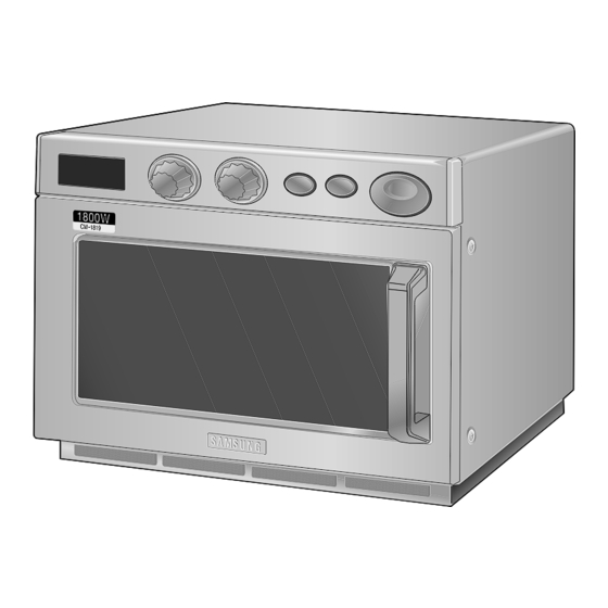
3. Operating Instructions 3-1 Features (CM-1819 / CM-1419) VARIABLE COOKING POWER CONTROL DIAL TIMER DIAL OVEN LAMP +20sec PAD DISPLAY STOP/CANCEL PAD OVEN LAMP COVER START BUTTON DOOR HANDLE CEILING COVER SAFETY INTERLOCK HOLES DOOR DOOR LATCHES PLATE TRAY AIR FILTER... - Page 6 6. DEFROST SELECTOR PAD 7. DOUBLE QUANTITY PAD 8. +20sec PAD (ONE TOUCH COOK PAD) 9. STOP/CANCEL PAD 10. START BUTTON 3-4 External Views (CM-1819 / CM-1419) 3-4-1 External Views (CM-1819 / CM-1419) 1000 3-4-2 External Views (CM-1829 / CM-1429) 1000...
- Page 7 Operating Instructions 3-5 Operation Guide (CM-1819 / CM-1419) Cooking/Reheating 1. Make sure the oven is plugged into a properly earthed electrical outlet and ‘ON’ appears in the display window. 2. Open the door. The oven lamp will be turned on.
-
Page 8: Using The Defrost Feature
Operating Instructions 3-5 Operation Guide (CM-1819 / CM-1419 continued) To stop the cooking You can stop cooking at any time so that you can: • Check the food • Turn the food over or stir it • Leave it to stand * Temporarily ;... - Page 9 ‘ON’ appears again. Food may be removed from oven whilst the fan is still running. 8. Open the door and take the food out. 9. Close the door. The oven lamp will go off. Samsung Electronics...
-
Page 10: Repeat Feature
Like traditional cooking, you may find that, depending on the food’s characteristics or your tastes, you have to adjust the cooking times slightly. Before operating the oven, times can be increased/decreased using either the time pads or +20sec button. During the operating, time may only be added by using the +20sec button. Samsung Electronics... -
Page 11: Memory Pads Programming
Memory programs are available up to 30 items. Make sure the unit is properly programmed. After programming is finished, all you have to do for memory cooking is to press the NUMBER pad. Then the selected memory program automatically starts cooking. Samsung Electronics... -
Page 12: How To Operate Memory Cooking
Result: Cooking stops. To resume cooking, close the door and press again. * Completely: Press the pad twice. Result: The cooking settings are cancelled. If you want to cancel any cooking settings before starting cooking, simply press CANCEL pad once. Samsung Electronics... -
Page 13: Power Levels And Time Variations
Operating Instructions 3-5 Operation Guide (CM-1829 / CM-1429 / CM-1819 / CM-1419) Power Levels and Time Variations The power level function enables you to adapt the amount of energy dissipated and thus the time required to cook or reheat your food, according to its type and quantity. You can choose between the power levels below. -
Page 14: Disassembly And Reassembly
4-2 Replacement of High Voltage Transformer 1. Discharge the high voltage capacitor. 2. Disconnect all the leads. 3. Remove the mounting bolts securing the HVT. 4. Reconnect the leads correctly and firmly. H. V. Trans 4 Mounting Bolts Samsung Electronics... -
Page 15: Replacement Of Door Assembly
2. Adjust so that the door has no play between the inner door surface and oven front surface. If the door assembly is not mounted properly, microwave energy may leak from the space between the door and oven. 3. Do the microwave leakage test. Samsung Electronics... - Page 16 If any of them are deformed, abnormal symptom can happen such as arcing or sparks during operation. Ass’y Stirrer Ass’y Stirrer Cover Plastic Clips Samsung Electronics...
- Page 17 Wire Harness-B Main P.C.Board (PCB1) Wire Harness-C Digitron(PCB4) Panel-Base Wire Harness-D PCB2 Button-Select Button-Start Main P.C.Board (PCB1) Control Box Ass’y (CM-1819/1419) Wire Harness-C Digitron(PCB4) Wire Harness-B Panel Base Wire Harness-F Window-Display Cover Panel PCB3 Cover-Panel/L Switch-Membrane Control Box Ass’y Cover-Panel/R...
-
Page 18: Replacement Of Lamp
3. Replace with a new lamp by rotating it counter- clockwise. Lamp Holder Lamp Cover NOTE : If it is necessary to replace the lamp holder, you can disconnect lead wires by pushing down on the hole of lead wires using a long pointed tool. Outer Panel Samsung Electronics... - Page 19 NOTE: It is not necessary to remove Magnetron in order to remove HVC. 1. Remove the outer panel and back cover. 2. Discharge the high voltage capacitor. 3. Remove HVT wire and H.V.Fuse. 4. Remove screws securing HVC bracket. H.V.Capacitor Samsung Electronics...
-
Page 20: Alignment And Adjustments
2. Once the capacitor is charged, a normal capacitor shows continuity for a short time, and then indicates 9MΩ. 3. A shorted capacitor will show continuous continuity. 4. An open capacitor will show constant 9MΩ. 5. Resistance between each terminal and chassis should read infinite. Samsung Electronics... -
Page 21: High Voltage Diode
Door Open Door Closed procedures. ∞ Primary S/W ∞ 4. Confirm that the gap between the switch housing Monitor S/W(COM-NC) ∞ Monitor S/W(COM-NO) and the switch actuator is no more than 0.5mm ∞ Door Sensing S/W when door is closed. Samsung Electronics... -
Page 22: Output Power Of Magnetron
3. After moving the water into another glass vessel, place it in the center of the cooking tray. Set the oven to high power and operate for 26 seconds for CM-1819/1829 or 33 seconds for CM-1419/1429 exactly. (3 seconds included as a holding time of magnetron oscillation) 4. -
Page 23: Check For Microwave Leakage
; CENTRAL SERVICE CENTRE 3) At least once a year have the microwave Thermistor Sensor Temperature energy survey meter checked for accuracy by its manufacturer. Samsung Electronics... -
Page 24: Troubleshooting
2. Defective high voltage components Check high voltage component (No heat while oven lamp H.V.Transformer according to component test procedure and fan motor turn on.) H.V.Capacitor and replace if defective. H.V.Diode, H.V.Fuse Magnetron Samsung Electronics... - Page 25 Oven can program Defective circuitry of Start function Check circuitry of Start function but timer does not of Main PCB Ass’y. of Main PCB Ass’y and replace if start. defective. Loose lead wires Adjust or repair loose wires. Samsung Electronics...
- Page 26 Check the circuitry. (Refer to Operating Sequence circuit failure as shown in page 42.) 1. Memory IC (EEPROM IC) Check Memory IC (IC3) and replace if defective. (CM-1829 failure /1429) 2. MICOM failure Replace Assy Main PCB or MICOM. Samsung Electronics...
- Page 27 7. Exploded Views and Parts List 7-1 Exploded Views CM-1829 CM-1429 CM-1819 CM-1419 (CM-1829/1429) (CM-1819/1419) Samsung Electronics...
-
Page 28: Exploded Views And Parts List
CM-1419/1429 DE59-40001A DIODE-H.V HVR-1X-32B-12 DE26-20162A TRANS L.V SLV-1829E 230 19.7/3.1V 50Hz 4 DE31-10180A MOTOR-VENTILATION SMV-1829EA 120V60Hz 2250rpm CM DE61-30189A SUPPORTER-FAN-MOUNT SECC T1.0 CM-1819 DE72-50088A DUCT-FAN ALCOAT T0.5 CM-1819 DE72-50089A DUCT-MGT/R SECC T0.5 CM-1819 DE72-50090A DUCT-MGT/L ALCOAT T0.5 CM-1819 DE61-50529A BRACKET-SUPPORT STS,0.8,NOISE... - Page 29 SGCC2 T1.0 W15 L8 DE71-60424A COVER-CEILING MICA_SHEET T0.5 W348 L319 CM-1 DE47-20017A THERMOSTAT PW-2N(150/60 187Z) 250V/7.5A 1 DE32-10013A SENSOR-THERMISTOR PT-312-K2 DE63-90191F CUSHION-GUIDE-F PUT-FOAM T10 W2 L700 CM1819/29 DE39-40693A WIRE HARNESS-A 230V50HZ CM-1819/29 EUROPE * S.N.A : Service Not Available Samsung Electronics...
- Page 30 SCREEN-DOOR(B) TEMP-GLASS T3.2 DE64-90146A DECORATION-COV/DOOR STS CM-1819 DE64-20123A HANDLE ZN-DICASTING 500G CM-1819 DE71-60433A COVER-HANDLE STS430 T0.5 CM-1819 DE64-40296A DOOR-KEY CR3C DE60-60080A PIN-KEY A M3.95 L21 STS304 CM-1819 DE61-70144A SPRING-KEY PI6.5 D0.8 CM-1819 DE61-80138A HINGE SCP1 T3.0 W24.5 L29.5 Samsung Electronics...
- Page 31 Exploded Views and Parts List 7-4 Exploded View & Parts List - Control Parts (CM-1819/1419) Ref. No Parts No. Parts Name Description/Specification Q'ty Remarks DE91-10512A ASSY PCB-MAIN CM-1819 230V50Hz VFD CM-1819 DE91-10514A ASSY PCB-MAIN CM-1419 230V50Hz VFD CM-1419 DE70-30126A PANEL-BASE...
- Page 32 DE70-30125A PANEL-BASE RESIN-ABS TC CM-1829 DE34-10237A SWITCH-MEMBRANE PE-SHEET 240V 0.5A 200GF 265x5 DE71-60426A COVER-PANEL STS430 T0.5 TC CM-1829 DE71-60428A COVER-PANEL/L RESIN-ABS CM-1819 Ni Cr-plating DE71-60429A COVER-PANEL/R RESIN-ABS CM-1819 Ni+Cr PLATING DE66-20212A BUTTON-START RESIN-ABS CM-1819 Ni Cr-plating DE67-40161A WINDOW-DISPLAY RESIN-PMMA 82555 CM-1819...
- Page 33 TH(WASHER) + 4 L12 MSWR18C N OUTPANEL DE60-10197A SCREW-WASHER TH(WASHER) + 4 L12 MSWR18C N SUP-FAN DE60-10197A SCREW-WASHER TH(WASHER) + 4 L12 MSWR18C N THERMISTOR DE60-20021A BOLT-HEX MSWR3 TAP 5X12S YELLOW HINGE DE60-30015A NUT-FLANGE M5 P0.8 MSWR10 FEFZY Samsung Electronics...
- Page 34 P.C.B Circuit Diagrams and Parts List 8-2 P.C.B Circuit Diagram (CM-1829 / CM-1429) Samsung Electronics...
- Page 35 P.C.B Diagrams and Parts List 8-3 P.C.B Parts List (CM-1819/1419) Parts No. Parts Name Description / Specification Q'ty Remarks DE91-10512A ASSY PCB-MAIN CM-1819 230V50Hz VFD 0604-000237 PHOTO-COUPLER TR 200mW DIP-4 ST IC4,5 3002-000198 BUZZER-PIEZO 80dB 4KHz ST BUZ1 3406-000175 SWITCH-ROTARY 28V 10mA DP36T 18.8mm...
- Page 36 P.C.B Diagrams and Parts List 8-3 P.C.B Parts List (CM-1819/1419 continued) Parts No. Parts Name Description / Specification Q'ty Remarks 2401-000180 C-AL 1000uF 20% 35V GP 16x25x7.5m 2401-000466 C-AL 10uF 20% 35V GP TP 5x7 5 2401-000598 C-AL 1uF 20% 50V GP TP 4x7 5...
- Page 37 DSP1 DE13-20016A IC-VOLT REGU KA7805A TO-220AB 1A 0/125C DE39-40113B WIRE HARNESS-F 100V 50/60HZ RE-CH1 DE39-40692A WIRE HARNESS-B 230V50HZ CM1819/29 EUROPE DE39-40694A WIRE HARNESS-C 230V50Hz CM-1819/29 EUROPE DE61-90178A HOLDER-DIGITRON NY66 CM-1819 DSP1 DE91-20593A ASSY PCB AUTO-MAIN 230V50Hz VFD CM-1829 0401-001002 DIODE-SWITCHING...
- Page 38 CONNECTOR-HEADER BOX 3P 1R 2.5mm STRAIGHT SN CN13,9 3711-000940 CONNECTOR-HEADER BOX 4P 1R 2.5mm STRAIGHT SN 3711-000999 CONNECTOR-HEADER BOX 5P 1R 2.50mm STRAIGHT SN DE13-20009A IC KA7533 DIP DE39-60001A WIRE-SO COPPER PI0.6 SN T 52MM TAPING_WIRE J04~06,08~38 J02(CM-1429) Samsung Electronics...
-
Page 39: Wiring Diagram & Operating Sequence
9. Wiring Diagram & Operating Sequence 9-1 Wiring Diagram (CM-1819/1419/1829/1429) Samsung Electronics... -
Page 40: Description Of Operating Sequence
1 and 2 is 30 seconds. The relation between indications on the display window and the output power of the microwave oven is as shown in figure below. CM-1819 / CM-1829 CM-1419 / CM-1429 c(d): 20% -> opt open - 7sec(8sec) 25% ->... - Page 41 NOTE : LAMP: Lamp Relay (250V 5A) MAIN: Main Relay (250V 16A) VENT: Ventilation Motor Relay (250V 5A) IR1: Inrush Relay1 (250V 5A) IR2: Inrush Relay2 (250V 5A) P1: Power Relay1 (250V 16A) P2: Power Relay2 (250V 16A) Samsung Electronics...
- Page 42 Relay open) is detected, the error code (E41, E42) shows on the display window. When the error code appears in the display window, check the waveform(A), (B), (C),or (D). In case of Power Relay 1 (RY2), check the waveform (A), (B) below. In case of Power Relay 2 (RY5), check the waveform (C), (D) below. Samsung Electronics...
Need help?
Do you have a question about the CM-1819 and is the answer not in the manual?
Questions and answers