Samsung CM1929 Service Manual
Hide thumbs
Also See for CM1929:
- Owner's instructions & cooking manual (352 pages) ,
- Service manual (41 pages) ,
- Owner's instructions and cooking manual (24 pages)
Table of Contents
Advertisement
Advertisement
Table of Contents

Related Manuals for Samsung CM1929


Summary of Contents for Samsung CM1929
- Page 1 08/2012 Mod: CM1929 Production code: CM-1929A...
- Page 2 BASIC: CM1929 CM1919 MODEL: CM1929 MODEL CODE: CM1929 VERSION: 0001,0002 1. Handle Door Design. 2. 0.9 cu.ft Cavity 3. High Power Output...
-
Page 3: Table Of Contents
• Contents 1. Precaution ................... . 3 1-1 Safety precautions . -
Page 4: Precaution
1. Precaution... -
Page 5: Safety Precautions
1. Precaution Follow these special safety precautions . Although the microwave oven is completely safe during ordinary use, repair work can be extremely hazardous due to possible exposure to microwave radiation, as well as potentially lethal high voltages and currents . 1-1 Safety precautions ( 1. -
Page 6: Special High Voltage Precautions
1. Precaution 1-2 Special High Voltage Precautions 1. High Voltage Warning Do not attempt to measure any of Discharge the 2 High Voltage Capacitors the high voltages --this includes the filament voltage of the before servicing! magnetron . High voltage is present during any cook cycle . Before touching any components or wiring, always unplug the oven and discharge the high voltage capacitor (See Figure 1-1) -
Page 7: Specifications
2. Specifications 2-1 Table of Specifications Model Items Model Basic Model New Model CM1929, CM1919/ELE CM1929 Timer Max . 25min (Power Level : HIGH) Max . 25min (Power Level : HIGH) Power Source 230V 50Hz, AC 240V 50Hz, AC Power Consumption... -
Page 8: Operating Instructions
3. Operating Instructions 3-1 Control Panel + 20sec DISPLAY DEFROST SELECTOR PAD PROGRAM PAD DOUBLE QUANTITY PAD PROGRAM LOCK PAD +20sec PAD (One Touch Cook Pad) NUMBER PADS(Time, Memory STOP/CANCEL PAD Programming) 10 . START BUTTON POWER LEVEL SELECTOR PAD... -
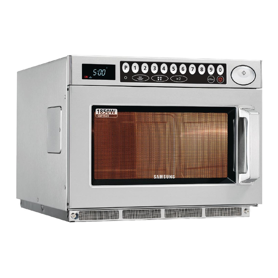
Page 9: Features & External Views
3. Operating Instructions 3-2 Features & External Views CONTROL PANEL OVEN LAMP (230V 25W) DISPLAY OVEN LAMP COVER START BUTTON CEILING COVER DOOR HANDLE SAFETY INTERLOCK HOLES DOOR PLATE TRAY DOOR LATCHES AIR FILTER 1000... -
Page 10: Disassembly And Reassembly
4. Disassembly and Reassembly 4-1 Replacement of Magnetron, Motor Assembly and Lamp Remove the magnetron including the shield case, Duct-MGT-L permanent magnet, choke coils and capacitor (all Nut-Flange of which are contained in one assembly) . Duct-Fan 1. Remove the outer panel . NOTE: Before servicing, make sure to discharge electric charge remaining on the high voltage capacitors or wait for more than 5 min . -
Page 11: Replacement Of Door Assembly
4. Disassembly and Reassembly 4-3 Replacement of Door Assembly 4-3-1 Removal of Door Assembly NOTE: Be sure to wear gloves when you disassemble or assemble the parts . 1 . Remove hex bolts securing the upper hinge and lower hinge . Then remove the door assembly . 2. -
Page 12: Replacement Of Fuse And H.v Fuse
4. Disassembly and Reassembly 4-4 Replacement of Fuse and H.V Fuse 1 . Disconnect the oven from the power source . 2. Remove defective fuse from Noise filter. 3 . When replacing the fuse, be sure to use an exact replacement part . -
Page 13: Replacement Of Control Circuit Box Assy And P.c.board
4. Disassembly and Reassembly 4-6 Replacement of Control Circuit Box Assy and P.C.Board 4-6-1 Removal of Control Box Assembly 1 . Be sure to discharge any static electric charge built up on your body and avoid touching the touch control circuitry . -
Page 14: Replacement Of Fan Motor
4. Disassembly and Reassembly 4-7 Replacement of Fan Motor 1 . Remove the outer panel and back-cover . Ventilation Motor 2 . Discharge the high voltage capacitor . 3 . Remove all the lead wires from Magnetron and High Voltage Capacitor . 4 . -
Page 15: Replacement Of Air Filter
4. Disassembly and Reassembly 4-10 Replacement of Air Filter 1 . Remove the bolt at both ends of the Air Filter . Then the locking clamps inside are released . 2 . Lift the Air Filter off the post carefully . NOTE : Spacer pins are not detachable from the Air Filter Bolt... -
Page 16: Alignment And Adjustments
5. Alignment and Adjustments PRECAUTION 1. High voltage is present at the high voltage terminals during any cook cycle . 2. It is neither necessary nor advisable to attempt measurement of the high voltage . 3. Before touching any oven components or wiring, always unplug the oven from its power source and discharge the high voltage capacitor . -
Page 17: High Voltage Diode
5. Alignment and Adjustments 5-4 High Voltage Diode 1. Isolate the diode from the circuit by disconnecting its leads . 2. With the ohm-meter set at the highest resistance scale, measure across the diode terminals . Reverse the meter leads and read the resistance . A meter with 6V, 9V or higher voltage batteries should be used to check the front-to back resistance of the diode (otherwise an infinite resistance may be read in both directions). -
Page 18: Output Power Of Magnetron
5. Alignment and Adjustments 5-7 Output Power of Magnetron PRECAUTION MICROWAVE RADIATION PERSONNEL SHOULD NOT ALLOW EXPOSURE TO MICROWAVE RADIATION FROM MICROWAVE GENERATOR OR OTHER PARTS CONDUCTING MICROWAVE ENERGY . The output power of the magnetron can be measured by performing a water temperature rise test . Equipment needed : •... -
Page 19: Procedure For Measurement Of Microwave Energy Leakage
5. Alignment and Adjustments 5-9 Procedure for Measurement of Microwave Energy Leakage 1. Pour 275±15cc of 20±5°C(68±9°F) water in a beaker which is graduated to 600cc, and place the beaker in the center of the oven . 2. Start to operate the oven and measure the leakage by using a microwave energy survey meter . -
Page 20: Troubleshooting
6. Troubleshooting PRECAUTION 1. CHECK GROUNDING BEFORE CHECKING FOR TROUBLE . 2. BE CAREFUL OF THE HIGH VOLTAGE CIRCUIT . 3. DISCHARGE THE HIGH VOLTAGE CAPACITOR . 4. WHEN CHECKING THE CONTINUITY OF THE SWITCHES OR TRANSFORMER, DISCONNECT ONE LEAD WIRE FROM THESE PARTS AND THEN CHECK CONTINUITY WITHOUT THE POWER SOURCE ON . - Page 21 6. Troubleshooting SYMPTOM CAUSE CORRECTIONS Oven lamp goes off 1. Loose lead wire or open filament Tighten lamp lead wire or replace with a new lamp 2 . Misadjustment of latch switch 3 . Defactive primary latch switch Microwave output is low; . 1 .
- Page 22 6. Troubleshooting 6-1 Electrical Malfunction (Continued)
- Page 23 6. Troubleshooting 6-1 Electrical Malfunction (Continued)
- Page 24 6. Troubleshooting 6-1 Electrical Malfunction (Continued)
-
Page 25: Error Codes & Corrections
6. Troubleshooting 6-2 Error Codes & Corrections CODE CAUSE CORRECTIONS 1 . Improper input power freqency . Check if power frequency is 50Hz . 2 . Defective Ass’y Main P .C .B Replace Ass’y Main P .C .B or MICOM 1 . - Page 26 7. Exploded Views and Parts List 7-1 Exploded Views...
-
Page 27: Exploded Views And Parts List
7. Exploded Views and Parts List 7-2 Main Parts List (S.N.A : SERVICE NOT AVAILABLE) Level Code No. Description Specification Q’ty SA/SNA Remark M036 4713-000168 LAMP-INCANDESCENT 230V,-,25W,ORG,-,-,- Z783 6011-001140 BOLT-STUD M4,L8,NI PLT,BSW M066 DE01-00095A FILM-LAMP -,PET,-,84,T0 .15,114,CM-1819,- M035 DE03-00009A MAGNETRON 2M244-M12E,1KW/2460MHZ,3 .15V/4 M038 DE26-00058A... - Page 28 B005 DE61-00066A SPRING-Q CM1819/1829,MSWR,PI0 .8,-,-,-,- B006 DE66-40062A LATCH-BODY -,-,-,-,-,-,- B012 DE66-90107A LEVER-SWITCH(U) PBT,CM-1819,-,-,-,-,- B013 DE66-90108A LEVER-SWITCH(L) PBT,CM-1819,-,-,-,-,- M015 DE96-00356G ASSY POWER CORD KKP-550A,-,250V15A,1700M W002 DE96-00503A ASSY-WIRE HARNESS A CM1929,230V 50HZ VI T002 DE97-00319A ASSY-TRAY CERAMIC CM1829,-,-,- T108 DE61-00170A FOOT-TRAY CM1049,URETHANE,-,WHT,-,-,-...
-
Page 29: Door Parts List
HINGE -,SHV-945EG1,KEC,T3 .0,W24 .5,L2 D019 DE64-20123A HANDLE CM-1819,ZN-DICASTING,-,-,-,-,C D011 DE64-40296A DOOR-KEY -,CR3C,-,-,-,-,-,- D006 DE64-40298A DOOR-C -,PP,-,-,-,-,-,- D021 DE64-90145A DECORATION-DOOR -,ABS,CM-1819,-,-,-,CM-1 D022 DE64-90146A DECORATION-COV/DOOR -,STS,CM-1819,-,-,-, D024 DE67-20174N SCREEN-DOOR(B) CM1929,GLASS,3 .2,198 .5,36 D026 DE71-60433A COVER-HANDLE -,STS430,T0 .5,CM-1819,-,-,- D004 DE92-50132B ASSY DOOR-E CM-1819,COATING,BLK... -
Page 30: Control Parts List
7. Exploded Views and Parts List 7-4 Control Parts List (S.N.A : SERVICE NOT AVAILABLE) Level Code No. Description Specification Q’ty SA/SNA Remark C082 DE93-30442T ASSY CONTROL-BOX -,CM1929,-,COMMERCIAL 0001VER CM1929,230V50HZ,BLACK,STS,ABS,HEA C082 DE94-02182A ASSY CONTROL-BOX 0002VER VY-COMMERCIAL MWO,MEMBRANE C001 DE93-30529N ASSY CONTROL-PANEL -,CM1329,-,COMMERCIAL C004... -
Page 31: Standard Parts List
7. Exploded Views and Parts List 7-5 Standard Parts List (S.N.A : SERVICE NOT AVAILABLE) Level Code No. Description Specification Q’ty Remark 6002-000630 SCREW-TAPPING PH,+,2S,M3,L8,ZPC(YEL),SWR MAIN PCB 6002-001325 SCREW-TAPPING TH,TORX,2S,M4,L12,ZPC(YEL) 6002-001326 SCREW-TAPPING OH,+,1,M4,L8,NI PLT SNA OUTER PANEL SIDE,COVER-LAMP,BASE 6006-001170 SCREW-ASSY TAPP WS,TH,+,M4,L10,ZPC(YEL) SNA S .MEM .EARTH,P/C EARTH,BKT-EARTH 6006-001176... -
Page 32: Schematic Diagrams
8. Schematic Diagrams 8-1 Schematic Diagrams (This Document can not be used without Samsung’s authorization) -
Page 33: Electrical Parts List
9. Electrical Parts List 9-1 Electrical Parts List (S.N.A : SERVICE NOT AVAILABLE) Level Code No. Description Specification Q’ty Remark RCS-D2CM-01 ASSY PCB PARTS CM1829 , 230V50HZ 0202-001341 SOLDER-WIRE FLUX RMA98,P3,M705,F2-5-A12E 0202-001538 ECO WIRE M708 3 .0MM 0204-002291 FLUX SV-PBF-302,ROSIN, R-NH3 HBR,HA 0604-000117 PHOTO-COUPLER TR,130-260%,200MW,DIP-4,ST... - Page 34 100uF,20%,10V,GP,TP,6 .3x7,5 C109 2401-000303 C-AL 100UF,20%,25V,GP,TP,6 .3X11,5 C105 2401-000598 C-AL 1uF,20%,50V,GP,TP,4x7,5 2401-000911 C-AL 22uF,20%,16V,GP,TP,5x7,5 C06,C07 2401-001573 C-AL 47uF,20%,50V,GP,TP,6 .3x11,2 .5 C108 2401-003505 C-AL 10UF,20%,450V,GP,TP,10X20MM,5 C102 2801-003933 CRYSTAL-UNIT 8MHZ,50PPM,28-AAA,12PF,70OH XTL1 DE09-00316A IC MICOM TMP87CM14F-4NK5,CM1929,64PIN,+ IC01 DE39-60001A WIRE-SO COPPER PI0 .5,SN,T,52MM,TAPING_WI J05~J29...
- Page 35 9. Electrical Parts List 9-1 Electrical Parts List(Continued) (S.N.A : SERVICE NOT AVAILABLE) Level Code No. Description Specification Q’ty Remark DE41-00334A PCB-MAIN RCS-D2CM,FR-1,1,-,T1 .6,296X197 2202-000253 C-CERAMIC,MLC-AXIAL 4 .7nF,20%,16V,Y5R,-, 2203-000555 C-CER,CHIP 0 .02NF,5%,50V,C0G,TP,2012 C03,C04 DE39-40692A WIRE HARNESS-B 11PIN,-,-,CM1819/29,-,-,- WIRE1 DE39-40694A WIRE HARNESS-C 9PIN,-,-,-,-,-,-,-,-,-,-, WIRE2 DE39-40113B...
-
Page 36: Wiring Diagrams
10. Wiring Diagrams 10-1 Wiring Diagrams (This Document can not be used without Samsung’s authorization) -
Page 37: Description Of Operating Sequence
2 is energized for 15 seconds in turn. One complete ON and OFF cycle time of the power relay 1 and 2 is 30 seconds. The relation between indications on the display window and the output power of the microwave oven is as shown in figure below. CM1919/CM1929 20% → opt open-7sec(8sec) c(d): 10% → opt open-4sec(11sec) - Page 38 10. Wiring Diagram and Operating Sequence 10-2 Description of Operating Sequence(Continued) Initial operating status of Power Relay when the START button is pressed. Relays are designed to work as shown in the figure below. When the oven is set to DEFROST power position, Inrush Relay1 and Power Relay1 are programmed to work with Inrush Relay2 and Power Relay2 not simultaneously but alternately.
- Page 39 10. Wiring Diagram and Operating Sequence 10-2 Description of Operating Sequence(Continued) High Voltage Transformer input power sensing circuitry Refers to the circuitry that detects and check if the input power is correctly supplied to the primary terminal of High Voltage Transformer when the microwave oven is operating. If any abnormal condition(eg.
-
Page 40: Reference
11. Reference 11-1 Model name standard Baoad Classification Distinguisher Middle Classfication Distinguisher Product Code Full Name CMO (Counter-top MWO) USA CMO(EPOXY CAVITY) UTC (Under The Cabinet) USA UTC Browner, Grill USA GRILL Convection USA CONVECTION USA CMO Sensor USA CMO SENSOR DC MWO USA DC MWO Hospital MWO... - Page 41 11. Reference 11-1 Model name standard (Continued) (Blue Color) : Not Used Baoad Distinguisher Middle Classfication Distinguisher Cavity / type Distinguisher Full Name Classification SOLO / CMO CME / CMC / CMW / CMS CERAMIC ENAMEL Inverter SOLO CIE / CIC / CIW / CIS Grill / Browner CGE / CGC / CGW / CGS CERAMIC...
-
Page 42: Customer Inquiry Cases And Countermeasures
• Close the door completely . => Press the Cancel the oven is out of order . button . => Press the Start button . • Contact the nearest Samsung after-sales service center . • Ground problem may • If the oven is placed in a humid area, buy an electric happen when the oven wire in a store selling electrical products . - Page 43 Error with Failure and Non- failure . • Visit the nearest Samsung Service Center or local dealer to buy accessories . Before visiting, check the model name printed on the lower right side of the front Accessory panel of the oven .
Need help?
Do you have a question about the CM1929 and is the answer not in the manual?
Questions and answers
How to open door frame and replace the door hook
To open the door frame and replace the door hook on a Samsung CM1929, follow these steps:
1. Remove the hex bolts securing the upper and lower hinges.
2. Take off the entire door assembly.
3. Use a flat screwdriver or thin metal plate (0.5 mm or less in thickness) to separate Door C from Door E by inserting it into the gap between them. Handle Door C carefully as it is fragile.
4. Remove the 2 screws that secure the Door Handle to the Door E assembly.
5. Unbend the 2 metal tabs at both ends of the Door Handle to remove the Door Handle Cover.
6. This will expose the internal components, allowing access to the door hook for replacement.
Make sure to reassemble all components in reverse order after replacing the door hook.
This answer is automatically generated
SAMSUNG CM 1929 1850 W WE HAVE ERA E41 CAN YOU ADVISE PLEASE.