Sign In
Upload
Download
Table of Contents
Contents
Add to my manuals
Delete from my manuals
Share
URL of this page:
HTML Link:
Bookmark this page
Add
Manual will be automatically added to "My Manuals"
Print this page
×
Bookmark added
×
Added to my manuals
Manuals
Brands
Fiat Manuals
Automobile
500L
Workshop manual
Fiat 500L Workshop Manual
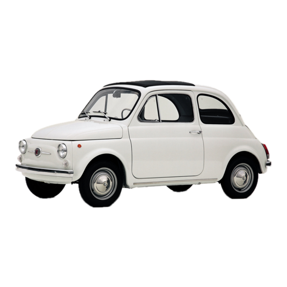
Fiat 500 1957-73
Hide thumbs
Also See for 500L
:
Owner's manual
(428 pages)
,
Owner's handbook manual
(224 pages)
,
User manual
(116 pages)
1
2
3
4
5
6
7
8
9
10
11
12
13
14
15
16
17
18
19
20
21
22
23
24
25
26
27
28
29
30
31
32
33
34
35
36
37
38
39
40
41
42
43
44
45
46
47
48
49
50
51
52
53
54
55
56
57
58
59
60
61
62
63
64
65
66
67
68
69
70
71
72
73
74
75
76
77
78
79
80
81
82
83
84
85
86
87
88
89
90
91
92
93
94
95
96
97
98
99
100
101
102
103
104
105
106
107
108
109
110
111
112
113
114
115
116
117
118
119
120
121
122
123
124
125
126
127
128
Table Of Contents
129
page
of
129
Go
/
129
Contents
Table of Contents
Bookmarks
Table of Contents
The Engine
Description
Left Side View of the Power Plant to Suit
Right Side Rear Three-Quarter View of the Power Plant for 500 Station Wagon
Engine Section through Crankshaft, Pistons and Valves
Engine Cross-Section through a Cylinder
Engine Removal
120.000 Engine Assembly: Cross-Section View through a Cylinder
Engine Compartment Lid Open
Engine Removal Using the Jack with Cross-Member
Engine Components: Crankcase, Cylinder Head, Timing Sprockets Cover
Tool A.40014 for Cylinder Head Removal
Removing Crankshaft Sprocket with Puller A.46020
Cylinder Hold-Down Tool A.601 56
Removal of Stud from Crankcase by Puller A.40010
Engine Without Blower Cowling and Cylinder Head Cover
Engine Disassembly (Station Wagon)
Tool A.60084 for Valve and Valve Spring Removal
Cylinder Head Removal, Servicing and Replacement
Cleaning Valve Guides
Installing a Valve Guide Using Tool A.60153 Provided with Pilot Bush
Main Specifications of Intake and Exhaust Valves and Valves Guides
Dismantling the Cylinder Head
Inspection and Servicing of the Cylinder Head
Valve Springs
Cylinder Head Installation
Timing Gear Overhaul
Valve, Pushrod and Tappet Assembly
Crankcase and Cylinders
Finned Cylinder
Cylinder Measurement Points
Honing or Reboring Cylinder Bores
Checking Cylinder Height
Inspection of Tappet Seats
Piston Assembly
Checking Piston Ring-To-Land Clearance
Reassembly of Piston
Checking Ring Gap (Ring in Cylinder)
Checking Rod Bearing Inserts and Crankpin Journals
Checking Rod Bearing Insert to Crankpin Journal Clearance
Connecting Rod Components
Installation of Connecting Rod Bearing Inserts
Little End Bushing
Engine Front End Without Flywheel
Piston-Connecting Rod Assembly
Crankshaft and Main Bearings
Camshaft End Crankshaft Supporting Member and Bearing Assembly, and Spare Main Bearing
Flywheel and Starter Ring Gear
The Oil Pump
Engine Lubrication Diagram
Pump Removal and Reassembly
Lubrication Diagram of Engine 120.000
Pump Dismantling, Inspection and Reassembly
Station Wagon
Pump Gears Removal, Inspection and Reassembly
Lubrication, Oil Filter, Relief Valve
Engine Longitudinal Section through Oil Pump
Centrifugal Oil Filter Components
Engine Detail Showing Lube Oil Passages
Cleaning and Inspection
Oil Pressure Indicator Sender Unit
Valve Timing
Valve Stem-To-Rocker Clearance Adjustment
Engine Assembly
Graduated Sector C.673 for Valve Gear Timing
Cylinder Head Hold-Down Nuts Tightening Sequence 500 Sedan
The Correct Position of Connecting Rod-Piston Assembly on Engine 120.000
Engine Assembly (Station Wagon)
Cylinder Head Stud Nut Tightening Sequence.500 D. F and L Sedan and Station Wagon
Power Plant Rear Suspension
Power Plant Mountings
Adjustment of Generator and Fan Drive Belt
Modifications
Fault Diagnosis
The Fuel System
Fuel Pump Operating Principles
Routine Maintenance
Pump Removal, Dismantling and Examination
Fuel Pump Components
Reassembly, Installation and Adjustment
Carburetter Operation and Adjustment, Weber 26.IMB
Fuel Pump and Control Pushrod
Carburetter Operation
Diagrammatic Section of Weber 26.IMB Carburetter
Starting Device (Choke) Diagrammatic Section
Weber 26.IMB Carburetter Starting Device (Choke) End
Starting Device
Engine Starting
Normal Car Driving
Idle Speed Adjustment
Adjustment of Fuel Level in Float Chamber:
Float Adjustment Data
Weber 26.IMB Carburetter Cover Components
Jets, Jet Holders and Choke Valve
Throttle Valve Components
Carburetter Cleaning
Carburetter Operation and Adjustment, Weber 26. OC
Carburetter Operation, Starting Device:
Section of Later Starting Device
Diagrammatic Section Views of 26.OC Weber Carburetter through the Starting Device
Diagrammatic Section Views of 26.OC Weber Carburetter
Float Level Setting Diagram Weber Carburetter Type 26.OC
Adjustment of Fuel Level in Float Chamber
Removing the Air Cleaner, 500F, L
Diagram of Blow-By Gases Re-Circulation Device
Air Cleaner (Sedan)
Air Cleaner—Engine 110 F.000
Air Cleaner—Station Wagon
Blow-By-Gases Recirculation Device
Location of the Fuel Tank in Front Compartment, 500F, L
The Ignition System
Adjusting the Contact Breaker Points
Cleaning the Contact Points
Ignition Faults
Testing the Low-Tension Circuit
Capacitor
Removing and Dismantling Distributor (Sedan and Sports)
Ignition Distributor in Place on Engine
Use of Fixture Ap.5030/1 to Check Ignition Timing
Removing and Dismantling Distributor (Station Wagon)
Timing the Ignition
Sparking Plugs
Sparking Plug Leads
The Distributor Driving Spindle (Sedan and Sports Engine)
The Cooling System
Engine Cooling Air Circulation System
Cooling Air Circulation System of Engine 120.000
Air Outlet Thermostat and Shutter
Tension Adjustment, Thermostat to Shutter Link
Location of Cooling Air Outlet Thermostat and Shutter
Diagram of the Heating System Safety Device (Sedan and Station Wagon)
Heating System Safety Device
The Clutch
Removal and Installation
Dismantling and Inspection of Clutch Cover
Assembly and Adjustment
Clutch Components (New 500, 500D Sedan and Early Station Wagon)
Inspection-Diaphragm Clutch
Clutch Assembly Installed on Engine
Clutch Cover Assembly Inspection Diagram 500F, L and Later Station Wagon
Installing the Clutch on Flywheel Using Pilot A.62023
Pilot Bushing
Clutch Controls and Adjusting Mechanism
Withdrawal Mechanism
Clutch Throw-Out Mechanism
Gearbox and Differential Unit
Gearbox-Differential Unit Longitudinal Section
Removal of Gearbox/Differential Unit
Gearbox Gears, Forks and Striker Rods
Detail of Gearbox Section through Striker Rod Positioning Ball Springs
Dismantling-Gearbox
Differential Unit Complete with Axle Shafts
Differential Components
Inspection of Components
Reassembly-Gearbox
Dismantling-Differential and Final Drive
Reassembly-Differential Unit
Final Drive Gear Set Adjustment
Graphic Demonstration of Values a and a
Setting Dial Indicator to Zero on Tool A.62037
Adjusting Final Drive Gear Set
Ring Gear Clearance and Differential Bearing Pre-Load
Check and Adjustment of Tooth Contact between Pinion and Ring Gear
Replacement of Gearbox-Differential Unit
Swing Axle Shafts and Slip Joints
Location of Gearshift Lever on Control Passage Tunnel
Gear Shift Control Mechanism
Dismantling and Inspection
Modified Items in Transmission-Differential Assembly
End Sectional View of Transmission-Differential Assembly
Rear Suspension and Wheels
Removal of Rear Suspension Assembly
Rear Suspension Assembly
Servicing Swing Arms
Right Rear Suspension Assembly, Sectioned through Brake Drum and Arm Mountings
Wheel Bearing Adjustment
Swinging Arm Adjustment
Installation of Rear Suspension Assembly
Adjusting Rear Wheel Toe-In Angle
The Position of Rear Suspension for Rear Wheel Toe-In Inspection and Adjustment
Checking Left Rear Wheel Toe-In
Sectional View of Right Side Rear Wheel and Axle Shaft
Front Suspension and Hubs
Front Suspension Removal and Dismantling
Front Suspension
Leaf Spring
Section through Left Swinging Arm
Section through One Spring Mounting
Front Leaf Spring, Loaded at Center
Front Leaf Spring, Installed on Car
Spring Deflection Test
Swinging Arm Components
Leaf Spring Inspection and Repair
Swinging Arms
Kingpin Housing
Steering Knuckle and Wheel Hub
Removing Right Front Wheel Hub Cap by Remover A.46023
Removing Left Front Wheel Brake Drum by Puller A.40005
Sectional View of Shock Absorber
Leaf Spring Position under Full Static Loads on Fixture A.66061 or A.74061
Hydraulic Damper
Installing Right Front Wheel Hub Cap by Tool A.66059
Front Suspension Assembly and Installation
Swing Arm Setting
Section through Steering Knuckle and Leaf Spring Mounting at Kingpin
Castor, Camber Angles
Steering Geometry
Adjustment of Castor Angle
Adjustment of Camber Angle
Steering System
Steering Wheel Removal and Refitting
Steering Box Removal and Refitting
Steering Box, Idler Member and Steering Linkage Arrangement on Vehicle
Securing Steering Wheel Mounting Nut
Steering Box Dismantling and Reassembly
Layout of Steering Gear Components
Section of Steering Box, through Worm Screw
Steering Box Cutaway
Refitting the Steering Box
Relay Lever and Support
Steering Rods (Tie Rods)
Front Wheel Toe-In Checking Diagram
The Braking System
Brake Adjustment (Station Wagon)
Preventative Maintenance
Diagrammatic View of Service and Rear Wheel Parking Brake System
Left Front Wheel Brake Assembly (500 Sedan)
Front Brake Drum Removal
Dismantling Brake Unit
Brake Shoe Lining
Reassembly of Front Brakes
Rear Brake Drum Removal
Reassembly of Rear Brakes
Master Cylinder Removal
Master Cylinder Section
Dismantling Master Cylinder
Refitting the Master Cylinder
Wheel Cylinder Operation
Brake Fluid Reservoir
Reassembling Wheel Cylinders
Self-Adjusting Device
Removing a Flexible Hose
Bleeding the System
Removing the Hand Parking Brake Cable
The Dual Circuit Braking System
The Electrical Equipment
The Battery
Battery Location
Cross-Section View of Battery
The Generator
Testing When Generator Is Not Charging
Removing Generator
Servicing Brushes
Servicing the Commutator
Components of Generator
Components of Starter
Testing Field Coils
Reassembly and Refitting the Generator
The Starter Motor
Tests for a Starter Which Does Not Operate
Removing the Starter
Examining the Commutator and Brush Gear
Testing the Field Coils
Wiring Diagram for Checking the Cutout Closing Voltage
Wiring Diagram for Checking the Reverse Current of Cutout
Reassembling and Refitting the Starter
The Control Box
Checking Cut-Out
Closing Voltage
Reverse Current
Checking Voltage/Current Regulator
Wiring Diagram for Setting the Cut-Out Relay
Wiring Diagram for Setting the Voltage Andcurrent Regulators
Wiring Diagram for Setting the Cutout Relay
Location of Electrical System Fuses
Cut-Out Relay Adjustment
Voltage Regulator Adjustment
Windshield Wiper Wiring Diagram
Faulty Operation of Flashers
Windscreen Wipers
Wiper Unit Faulty Operation
Removal and Refitting the Motor
Headlamp Removal
The Lighting System
Replacement of Bulb from Inside Front Compartment
Disassembling Front Parking and Direction Indicator Lamp
Beam Setting
Disassembling Tail Parking, Stop, Direction Indicator Lamp and Reflector Lens
Lamp Brilliance Varies with the Speed of the Car
Fuel Reserve Supply Indicator Sender Unit
Number Plate Lamp
Horn (Opened)
Lighting and Flasher Switch
Switch Unit Removal
Bodywork Finish
Interior and Chrome Cleaning
Cleaning Imitation Leather
Chrome Plated Parts
Door Trim and Accessories
Weather Strip
Advertisement
Quick Links
1
The Engine
Download this manual
See also:
Owner's Manual
,
User Manual
FIAT 500 1957-73
Workshop Manual
Autobooks
Models Covered
Fiat New 500
Fiat 500D
Fiat 500F
Fiat 500L
Fiat and Autobianchi Giardiniera
Table of
Contents
Previous
Page
Next
Page
1
2
3
4
5
Advertisement
Table of Contents
Need help?
Do you have a question about the 500L and is the answer not in the manual?
Ask a question
Questions and answers
Related Manuals for Fiat 500L
Automobile Fiat 500L Owner's Manual
(428 pages)
Automobile Fiat 500L Owner's Handbook Manual
(224 pages)
Automobile Fiat 500L User Manual
2014 (116 pages)
Automobile Fiat 500L Quick Manual To Repairs
(18 pages)
Automobile Fiat 500 Abarth Owner's Manual
2013 (380 pages)
Automobile Fiat 500 Owner's Handbook Manual
(228 pages)
Automobile Fiat 500 Owner's Handbook Manual
(218 pages)
Automobile Fiat 500 C Owner's Handbook Manual
(164 pages)
Automobile Fiat 500 Collision Awareness Manual
(144 pages)
Automobile Fiat 500 Abarth User Manual
2012 (116 pages)
Automobile Fiat 500 User Manual
2012 (116 pages)
Automobile Fiat 500 User Manual
(100 pages)
Automobile Fiat 500 Abarth User Manual
2013 (80 pages)
Automobile Fiat 500 Warranty Information
(38 pages)
Car Receiver Fiat 500 Manual
Sound system (30 pages)
Automobile Fiat 500 Supplement Manual
(24 pages)
This manual is also suitable for:
500f
500d
500
Table of Contents
Save PDF
Print
Rename the bookmark
Delete bookmark?
Delete from my manuals?
Login
Sign In
OR
Sign in with Facebook
Sign in with Google
Upload manual
Upload from disk
Upload from URL
Need help?
Do you have a question about the 500L and is the answer not in the manual?
Questions and answers