Table of Contents
Advertisement
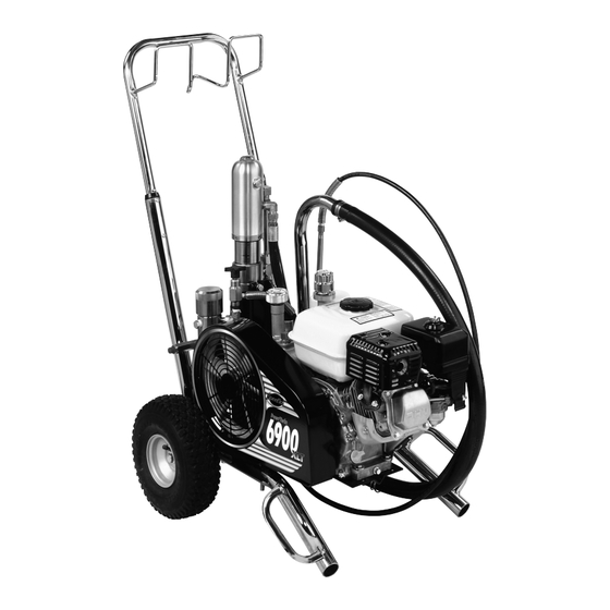
PowrTwin 6900
0Model Number:
Gas Bare
Gas Complete
DC Electric Bare
Gas/Electric Complete
Printed in the U. S. A.
448-305
448-310
448-315
448-320
Owner's Manual
For professional use only
Do not use this equipment
before reading this manual!
NOTE: This manual contains important warnings
and instructions. Please read and retain for
reference.
0205 © 2005 Titan Tool Inc. All rights reserved. Form No. 313-2495A
XLT
Advertisement
Table of Contents

Related Manuals for Speeflo PowrTwin 6900XLT


Summary of Contents for Speeflo PowrTwin 6900XLT
- Page 1 Owner’s Manual For professional use only Do not use this equipment before reading this manual! PowrTwin 6900 0Model Number: Gas Bare 448-305 Gas Complete 448-310 NOTE: This manual contains important warnings and instructions. Please read and retain for DC Electric Bare 448-315 reference.
-
Page 2: Table Of Contents
Table of Contents WARNING Safety Precautions....... . . 2 Grounding Instructions ......3 HAZARD: Injection injury - A high pressure stream Gasoline Engine Safety . -
Page 3: Grounding Instructions
Grounding Instructions • Power cord must be connected to a grounded circuit (electric models only). Electric models must be grounded. In the event of an • Always flush unit into a separate metal container, at low electrical short circuit, grounding reduces the risk of electric pump pressure, with spray tip removed. -
Page 4: Gasoline Engine Safety
313-1837 Electroless nickel plated ductile iron, electroless nickel plated labels, order directly from carbon steel, stainless steel, tungsten carbide, , thiokol 313-1306 Spanish Speeflo free of charge. impregnated leather, ultra high molecular weight polyethylene. 313-1307 313-785 French 313-786 313-787 German 313-788 ©... -
Page 5: Introduction
Operation Congratulations on having selected the finest airless sprayer Fueling (gas engine) available in the world. Speeflo piston pumps are tireless workhorses — so tough they are virtually indestructible, even under the most severe service. Speeflo designs and builds WARNING equipment with superior quality and reliability. -
Page 6: Setup
Refer to the Maintenance section of this manual for hydraulic system maintenance instructions. CAUTION Use of Speeflo's Coolflo™ Hydraulic Fluid is mandatory in the hydraulic system. Do not use any other hydraulic fluid. Use of any other hydraulic fluid may seriously damage the hydraulic system and will void the warranty. -
Page 7: Preparing To Paint
Preparing a New Sprayer Preparing to Paint If this unit is new, it is shipped with test fluid in the fluid section Before painting, it is important to make sure that the fluid in the to prevent corrosion during shipment and storage. This fluid system is compatible with the paint that is going to be used. -
Page 8: Painting
b. To start the electric motor, move the ON/OFF switch to WARNING the ON position. 7. Turn the pressure control knob clockwise approximately 1/3 of the way down to increase pressure until the sprayer Ground the gun by holding it against the cycles evenly and paint flows freely from the bleed hose. -
Page 9: Pressure Relief Procedure
Pressure Relief Procedure 3. Place the siphon tube into a container of the appropriate solvent. WARNING CAUTION Be sure to follow the pressure relief procedure when Use only compatible solvents when cleaning out oil based shutting the unit down for any purpose, including enamels, lacquers, coal tar, and epoxies. -
Page 10: Cleaning A Clogged Tip
Cleaning a Clogged Tip Maintaining the Filter Assembly 1. Follow the “Pressure Relief Procedure” in the Operation Clean the filter regularly. Dirty or clogged filters can greatly section of this manual. reduce filtering ability and cause a number of system problems including poor spray patterns, clogged spray tips, etc. -
Page 11: Maintaining The Hydraulic System
2. Change the hydraulic fluid every twelve months. Drain 3. Clean and re-gap the spark plug. the old fluid from the tank and fill with 5 quarts of Speeflo 4. Clean the spark arrestor. Coolflo™ Hydraulic Fluid (6 quarts when also replacing Weekly the hydraulic filter). -
Page 12: Replacing The Motor Brushes (Electric Motor)
Replacing the Motor Brushes WARNING (electric motor) Perform this procedure using Motor Brush Kit P/N 978-050. If electric motor overloads and stops running, The kit consists of two brushes, two springs, and two clips. IMMEDIATELY turn the motor off and follow the Pressure Relief Procedure in the Cleanup section of this manual. -
Page 13: Troubleshooting
Troubleshooting Airless Gun Problem Cause Solution Spitting gun 1. Air in system 1. Inspect connections for air leaks. 2. Dirty gun 2. Disassemble and clean. 3. Needle assembly out of adjustment 3. Inspect and adjust. 4. Broken or chipped seat 4. -
Page 14: Hydraulic Motor
Troubleshooting Hydraulic Motor Problem Cause Solution Oil motor stalls at bottom (no 1. Fluid pump piston seat unthreaded 1. If connecting rod is okay, remove cylinder unusual heat problems) head plug and pop valve down. Replace plug and start machine. If machine cycles up and stops at bottom again, then problem is piston seat on fluid pump. -
Page 15: Spray Patterns
Troubleshooting Spray Patterns Problem Cause Solution Tails 1. Inadequate fluid delivery 1. Fluid not atomizing correctly: Increase fluid pressure. Change to smaller tip orifice size. Reduce fluid viscosity. Reduce hose length. Clean gun and filter(s). Reduce number of guns using pump. - Page 16 Consignes de sécurité DANGER : RISQUES D’EXPLOSION OU D’INCENDIE – Les émanations de solvants et de peinture sont Le présent manuel contient des renseignements à lire attentivement et explosives et inflammables. Elles peuvent causer à bien comprendre avant d'utiliser l'équipement. Lorsque l’un des des blessures corporelles ou des dommages matériels importants.
- Page 17 DANGER : GÉNÉRALITÉ – Ce produit peut provoquer des Sécurité des moteurs à essence blessures ou des dégâts matériels graves. PRÉVENTION: • Lisez attentivement toutes les instructions et les consignes de AVERTISSEMENT sécurité avant de faire fonctionner l'appareil. • Débranchez toujours le moteur de la source d'alimentation Les produits chimiques contenus dans les vapeurs électrique avant de travailler avec l'équipement (modèles d'échappement de cet appareil sont reconnus par l'État de la...
- Page 18 Precauciones de seguridad PELIGRO: EXPLOSIÓN O INCENDIO – Los vapores de solventes y pinturas pueden explotar o incendiarse. Se pueden Este manual contiene información que debe leer y comprender antes producir lesiones graves y daños materiales. de usar el equipo. Cuando se encuentre con uno de los siguientes PARA PREVENIR: símbolos, preste especial atención y observe sus indicaciones de •...
- Page 19 Seguridad del motor de gasolina PELIGRO: GENERAL – Este producto puede causar graves lesiones o daños materiales. PARA PREVENIR: ADVERTENCIA • Lea todas las instrucciones y advertencias antes de hacer funcionar el equipo. • Desconecte siempre el motor de suministro eléctrico antes de dar El escape del motor de esta unidad contiene productos químicos servicio al equipo (sólo modelos eléctricos).
-
Page 20: Parts Lists And Service Instructions
Parts Lists and Service Instructions Main Assembly Item Part # Description Quantity Item Part # Description Quantity 235-118 Motor/pump assembly ......1 ---------- Hydraulic system ........1 703-137 Swivel fitting assembly (includes item 5) .1 449-181 Belt, "V" ...........1 ---------- Bleed hose assembly w/valve ....1 506-275 Convertokit, 5.5 HP, Honda, gasoline 930-515... -
Page 21: Cart Assembly
Cart Assembly (P/N 335-020) Item Part # Description Quantity Item Part # Description Quantity 590-502 Handle ............1 590-507 Snap button ..........2 449-055 Motor/pump bracket .........1 590-504 Sleeve ............2 862-460 Screw ............1 590-506 Washer .............2 590-100 Retaining ring ...........4 856-002 Washer .............4 870-009 Washer .............4 856-921... -
Page 22: Hydraulic System
Hydraulic System Item Part # Description Quantity 313-755 Knob decal ..........1 862-414 Set screw..........1 448-243 Pressure control knob ......1 860-520 Set screw..........1 449-195 Pulley/fan assembly .........1 448-494 Key, pump (.156 x .156 x 1 3/16 ) ....1 449-752 Hydraulic pump ........1 431-042 Tube connector ........1 858-636... -
Page 23: Dc- Electric Convertokit
DC - Electric Convertokits ON/OFF switch is also circuit breaker reset CSA Approved Motor 506-211 506-205 506-211 506-205 115V CSA, 115V 115V CSA, 115V Item Part # Description Qty. Qty. Item Part # Description Qty. Qty. 506-259 Cover ........1....1 977-228 Pulley ........1 860-501 Nut stop ......4....4... -
Page 24: Gas Convertokit
Gas Convertokit (P/N 506-275) Filter Assembly 930-514 930-515 930-516 Item Part # Description Qty. Qty. Qty. 930-937 Filter cap assembly ..1....1 ...1 930-020 Spring ......1....1 ...1 930-005 Filter element, 5 M, w/ball ....1 930-006 Filter element, 50 M, w/ball ........1 Item Part # Description... -
Page 25: Bleed Valve Assembly
Bleed Valve Assembly (P/N 944-030) Siphon Hose Assembly 103-816 103-817 Item Part # Description Qty. Qty. 420-070 Hose........4.5'....6.5' 103-679 Hose clamp .......2 ....2 103-575 Tube ........1 103-585 Tube ............1 103-627 Rock catcher .....1 ....1 Item Part # Description Quantity 194-771 Adapter ......1 ....1 944-034 Valve handle..........1... -
Page 26: Hydraulic Motor
Hydraulic Motor See page 31 for installation instructions. Item Part # Description Quantity Motor Service Kit — Minor (P/N 235-050) 235-018 Trip retainer ..........2 Item Part # Description Quantity 141-007 O-ring ............2 141-007 O-ring ............2 325-005 Trip spring, ..........2 325-005 Trip spring ..........2 569-016 Ball, SS.............2... - Page 27 3. Place the motor/pump assembly in a vise, holding it 3. Install sleeve retainer (13) followed by snap ring (14) into securely by the motor/pump block (25). cylinder head (11), which will hold valve sleeve in place. Install o-ring (12) in the o-ring groove of the cylinder head. 4.
-
Page 28: Français
Hydraulic Motor Cut-Away Fluid Section Torque head plug to Torque flex locknut to 15 ft./lbs. (219 N/m). 10 ft./lbs. (146N/m). Do not over-tighten Use blue Loctite. o-ring seal. Motor/ Pump Block Torque trip retainers to 15 ft./lbs. (365 N/m). Do not over-tighten o-ring seal. - Page 29 Use of non-Speeflo service parts may void warranty. Ask motor/pump block. for original parts made by Speeflo for best services. This pump should receive a routine servicing after approximately 11. Insert the upper packing set (4) into the motor/pump block 1,000 hours of use.
-
Page 30: Gun Manifold Assemblies (Optional)
Gun Manifold Assemblies (Optional) SIngle Gun Add-On Manifold Assemblies Add-A-Gun Kit 1-Gun Add-On Kit 975-111 975-311 975-200 975-300 1 Gun Add-On 1 Gun Add-On Add-A-Gun Kit Add-A-Gun kit Item Part # Description 1/4" 3/8" 1/4" 3/8" 814-002 Nipple, Hex .......1 ..............1 814-004 Nipple, Hex............1..............1 940-553... -
Page 31: Sae O-Ring Fitting Installation
SAE O-Ring Fitting Installation Accessories and Service Kits These items may be purchased separately from your local Speeflo distributor. Steps 1 & 2: Lubricate Part # Description 103-816 5 Gal. Siphon Hose Assembly w/Rock Catcher 1" x 4.5' 103-817 55 Gal. Siphon Hose Assembly w/Rock Catcher Lubricate 1"... -
Page 32: Limited Warranty
Limited Warranty Titan Tool, Inc., (“Titan”) warrants that at the time of delivery to the original purchaser for use (“End User”), the equipment covered by this warranty is free from defects in material and workmanship. With the exception of any special, limited, or extended warranty published by Titan, Titan’s obligation under this warranty is limited to replacing or repairing without charge those parts which, to Titan’s reasonable satisfaction, are shown to be defective within twelve (12) months after sale to the End User.
Need help?
Do you have a question about the PowrTwin 6900XLT and is the answer not in the manual?
Questions and answers