Table of Contents
Advertisement
Quick Links
Advertisement
Table of Contents
Troubleshooting

Related Manuals for POSEIDON MKVI


Summary of Contents for POSEIDON MKVI
- Page 1 Poseidon MKVI User Manual Chapter 1 Page 1 POSEIDON MKVI USER MANUAL...
-
Page 2: Table Of Contents
3. Counter lungs to BCD / Harness..............15 Part 1 – Preparation 4. Rear CC hoses to counter lung...............16 5. Rear CC loop hoses..................18 An Overview of the Poseidon MKVI ................1 6. Attaching the cylinders..................20 Primary Display ....................1 7. E-module......................21 Open-Circuit / Closed-Circuit Mouthpiece............2... - Page 3 Managing ascents ....................61 Units of measure ..................51 Ending the dive ....................61 Alarm signal area ..................51 Safe diving with the Poseidon MKVI ..............62 Abort! and open circuit alerts ................51 DO NOT DIVE alert ..................51 Chapter 4 - Post-dive care and maintenance General alert ....................52...
- Page 4 40m Deco Version ..................85 48m/60m Deco / Trimix Version ..............85 Maximum TTS....................85 Appendix 1 - Troubleshooting guide Pre-Dive Procedures with a MKVI enabled for Decompression Diving ....86 48m/60m Deco Trimix ..................86 Automatic pre-dive test ..................68 Switching in between batteries ................86 Standard response to test failure ..............69...
-
Page 5: Conventions Used In This Guide
Alert boxes that are RED contain extremely critical information related to the safety and well-being of the diver. Failure to comply On certain pictures in this manual the MKVI rebreather may be equipped with with information contained in these boxes could lead to serious accessories which are not part of the standard scope of delivery. -
Page 6: Preface
1 Unlike open-circuit scuba, the rate of gas consumption on the Poseidon MKVI does not depend on the depth of the dive. Instead, the oxygen supply depends on how fast the diver consumes oxygen through metabolism. -
Page 7: Conformance With Ce Requirements
CE approval and they are NOT the exact specifications of the Poseidon MKVI. (39º Farenheit), and a maximum of 35º Celsius (95º Farenheit). Operation at temperatures The exact specifications and values of the MKVI can be found in the later chapters of this outside of this range may lead to unreliable function. - Page 8 Poseidon MKVI User Manual Chapter 1 Page vii Chapter 3 of this Manual describes procedures for donning and fitting of the MKVI, to ensure proper positioning on the diver, as well as instructions for proper use while conducting a dive.
-
Page 9: Chapter 1 - Preparation & Assembly
Poseidon MKVI. Figures 1-1 and 1-4 illustrate these loca- tions and the main systems of the Poseidon MKVI. The “left” side of the rig Right side water corresponds to a diver’s left side when wearing the rig normally; the “right”... -
Page 10: Open Circuit/Closed Circuit Mouthpiece
Page 2 Open circuit/closed circuit mouthpiece One of the most amazing of several technology breakthroughs in the Poseidon MKVI is its switch-able mouthpiece. It incorporates a high-performance lightweight open-circuit regulator, and you can breathe it just that way, just like standard scuba. With a simple quarter-turn of an easy-to-operate switch, the system is ready for fully closed-circuit, bubble-free, silent, depth- independent diving. -
Page 11: Breathing Loop Overview
Chapter 1 Page 3 Breathing loop overview The most visible elements of the front portion of the Poseidon MKVI comprise Electronics module the breathing loop: breathing hoses; convertible open and closed-circuit mouthpiece with built-in automatic diluent addition valve (ADV); water diver-... -
Page 12: Carbon Dioxide Absorbent Cartridge
Cartridge Housing discussion. Gas injection module In a fully-closed rebreather like the Poseidon MKVI, oxygen is consumed by the diver and a mechanism must be provided for replacement of that used oxygen. Otherwise the mixture will slowly be depleted to dangerously oxygen low levels (hypoxia). The MKVI is designed to... -
Page 13: Smart Battery Care
Poseidon MKVI User Manual Chapter 1 Page 5 Receiver Safety latch slot Figure 1-6. Smart battery module Smart battery care Retainer screw post Figures 1-7 shows the installation procedure for the smart battery. The battery contains four Figure 1-7. (Left) Align the retainer screw posts on the Smart Battery with the receiver slots... -
Page 14: Charging
Page 6 Charging Included with the Poseidon MKVI is a proprietary multi-function desk-top charger unit that includes adapters for most international power outlets. The battery charger has three status lights arranged in a circular pattern on the open section of the base. These are, in counter- clockwise order from the lower left in Figure 1-9: power, “Learn Cycle”... -
Page 15: Long-Term Storage
If someone wearing the MKVI accidentally falls into the It is strongly recommended that you use the same battery in the same Poseidon MKVI for any water, the system will automatically power up the rig, enhancing the probability for survival of the user. -
Page 16: Dive Log Data
The information stored in this log will be of significant interest in reconstructing dives and learning about how the rig and you behave during a dive. A Windows-based MKVI dive log reviewer are available as a download from Poseidon (www.poseidon.com). In general, the unit DANGER: will store approximately 20 hours of dive time;... - Page 17 A second, and more commonly used seal is the “ radial “ o-ring. Figure 1-11 shows a typical Sealing surface for ”radial” o-ring seal implementation in the Poseidon MKVI breathing hose and hose connection ports. In contrast to a axial o-ring seal, a radial seal involves a circular groove that goes around a cylindrical or...
-
Page 18: Cylinders And Regulators
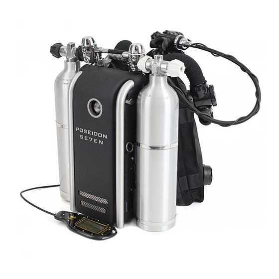
Poseidon MKVI User Manual Chapter 1 Page 10 Cylinders and regulators The Poseidon MKVI (EU version only) is factory-issued with two 3-liter aluminum cylinders with Poseidon post-style valves (see Figure 1-12). The oxygen cylinder has a white valve knob and DANGER: the diluent cylinder has a black valve knob. -
Page 19: Filling The Cylinders
General examples of diluent gases that can be used in rebreathers include: air, nitrox, trimix, and heliox. The MKVI is in its recreational configuration limited to 40m / 130 feet depth and uses only air as an allowed diluent, following established compressed air scuba sport diving practices. -
Page 20: Part 2 - Assembly
Please note that the Besea harness and the 11-inch adapter are both sold separately and are not included in the Poseidon MKVI. The pre-packed scrubbers are consumables and are sold separately and not included in the MKVI. Standard tank band supplied with the MKVI, quick release buckles on the items sold separately. -
Page 21: Stabjacket / Bcd / Wing
This is to allow more experienced divers the choice of using an existing personal backpack, harness, and buoyancy compensator. Poseidon supplies the tightly-integrated Besea, harness, and buoyancy wing system for use with the MKVI. The front extrusion rail on the Poseidon MKVI accepts the 11-inch adapter (see Figure 1-13). Attachment of the Besea is as quick as aligning the 11-inch adapter pin-bolts to the upper holes in the Besea harness as shown in Figure 1-13. -
Page 22: Tank Band
Poseidon MKVI User Manual Chapter 1 Page 14 2. Tank band Figure 1-14a. Tank band (assesory). The tank band buckles should be aligned so that they are folded backwards when the tank is securly locked in place. Thread the tank band through the tank band bracket, from the back towards the front. -
Page 23: Counter Lungs To Bcd / Harness
(Figure 1-16) attach the counterlungs to the shoulder straps of the backpack. The MKVI is provided with a lower D-ring and a crotch strap that connect to the Connect the small male plastic clip on the upper part of the counter lung to the female plastic bottoms of each counterlung. -
Page 24: Rear Cc Hoses To Counter Lung
Poseidon MKVI User Manual Chapter 1 Page 16 4. Rear CC hoses to counter lung T-connections. Connect the T-connection to the top port in each counter lung. Radial seal surface Radial o-ring seal Thread connection post Figure 1-17. Insert the right hand water diversion manifold into the port on the right counterlung. - Page 25 Poseidon MKVI User Manual Chapter 1 Page 17 Figure 1-19 shows a cross section of the water diversion manifold. A quick inspection will show that on one side (the “front”) you can insert a finger and feel an open vertical tube leading down to the threaded counterlung connection post (see Figure 1-19).
-
Page 26: Rear Cc Loop Hoses
There are a total of eight (8) hose connections to be made in the assembly of the Poseidon MKVI. Assembly of these hoses starts at the gas processor, and continues forward Repeat these steps with the right rear breathing hose, so the rig is as shown in Figure 1-21. - Page 27 Poseidon MKVI User Manual Chapter 1 Page 19 Figure 1-25. Attach the right counterlung Figure 1-26. Attach the left rear breathing water diversion manifold to the right rear hose to the left counterlung shoulder port. breathing hose. ”Radial” o-ring seal Sealing surface for ”radial”...
-
Page 28: Attaching The Cylinders
6. Attaching the cylinders Attach the two tanks to the canister housing tank connections and secure them with the tank The Poseidon MKVI is equipped with one mounting bracket holding two nylon cylinder straps straps. with cam buckles on each side. Attachment of the diluent cylinder (black valve handle) is illus- trated in Figures 1-27 and 1-28. -
Page 29: E-Module
7. E-module Check and make sure that the two o-rigs around the e-module are in place and without At the heart of the Poseidon MKVI is an electronic, pneumatic, control, and user feedback damage. system. The electronics module, shown at the center of Figure 1-29, contains the primary... - Page 30 DANGER: The electronics module contains the most important life-critical element of the Poseidon MKVI: the oxygen sensors. A leak into the electronics housing may contaminate the oxygen sensors WARNING: and prevent them from providing correct readings. Dual radial...
-
Page 31: 8. 1St Stages
If contamination occurs, the compromised components Figure 1-32. should be taken to an authorized Poseidon Tech Center representative or a qualified tech dive 16 cm Low Pressure hose’s shop technician for oxygen cleaning. - Page 32 Never expose these components to compressed air, which can contaminate components with oil. Always have these components cleaned and serviced by a Poseidon Tech Center representative or other qualified personnel. Always use oxygen- compatible lubricants when servicing o-rings and seals. Open oxygen cylinder valves slowly.
-
Page 33: Lp Hose & Hud To Mouthpiece
Poseidon MKVI User Manual Chapter 1 Page 25 9. LP hose & HUD to mouthpiece Figure 1-38. Connect the long braided 90 cm Low Pressure hose to a IP port on the diluent 1st stage. Twine the HUD cable around See Figure 1-37. -
Page 34: 10. Jetstream Octopus
Chapter 1 Page 26 10. Jetstream Octopus The Poseidon MKVI is delivered with an alternative air source (i.e. Octopus) that should be connected to the diluent 1st stage. To fully understand the funktions of the Jetstream Octopus, please read the Jetstream Octopus manual. -
Page 35: 11. Front Cc Hoses To Counter Lung T-Section
Poseidon MKVI User Manual Chapter 1 Page 27 11. Front CC hoses to counter lung T-section Connect the left front CC loop hose to the inhalation counter lung T-connection. Lay out the two remaining breathing hoses. Connect the right front breathing hose to the front port of the right counterlung water diversion manifold (Figures 1-43). -
Page 36: 12. Front Cc Hoses To Mouthpiece
Connect the front right CC loop hose to the exhalation side CC loop hose connection of the valve only with a Poseidon original manufacture mouthpiece checkvalve. Attach the right hand mouthpiece. - Page 37 IMPORTANT: Poseidon original manufacture mouthpiece checkvalve. Attach the left front breathing hose to The left and right checkvalves and their carrier plates in the the upstream CC port as shown in Figure 1-45, following the standard hose connection pro- mouthpiece are identical to each other.
-
Page 38: 13. Scrubber
CO absorbent cartridge. the MkVI to 60m reduces the performance. At 60m the canister has been tested for a duration of 120 minutes, water temp 4°C, and a breathing rate of 40lpm producing 1.6 l CO2 per... - Page 39 It is also good practice to rinse, disinfect, and dry the absorbent sponge following a dive. Any disinfectant solution that doesn’t have a negative effect on plastics and/or rubber can be used for this purpose. Poseidon recommends using a Figure 1-49. Remove the End Plate.
- Page 40 It is good practice to rinse, disinfect, and dry the lower absorbent sponge following a dive. Any disinfectant solution that doesn’t have a negative effect on plastics and/or rubber can be used for this purpose. Poseidon recommends using a disinfectant called Gigasept™ or a disinfec- tant called Virkon.
- Page 41 Figure 1-56. Figure 1-57. Figure 1-58. Figure 1-59. Loading the Cartridge End Cap into the Loading the Poseidon MkVI Cartridge Insert cartridge top plate and inspect Inspect and lubricate cartridge housing new replacement SofnoDive ® Top Cap into the replacement Sofno- the face-seal o-ring.
- Page 42 O-rings and their sealing surfaces are at the heart of reliable operation of the Poseidon MKVI. Pay attention to this detail when you assemble the rig.
- Page 43 Because CO exists naturally in the atmosphere, a SofnoDive doubt, leave the cartridge inside the Poseidon MKVI and store it 797 cartridge openly exposed to the atmosphere will expire in 24 with the mouthpiece in the open-circuit (OC) switch position to hours.
-
Page 44: Servicing
Chapter 1 Page 36 Servicing Poseidon MKVI cylinders should be hydro-tested once every five years and visually inspected yearly. Regulators should be rebuilt every two years. Oxygen regulators, cylinders, and cylinder valves should be oxygen cleaned every two years. All of these services form a part of the Poseidon Tech Center biannual service. -
Page 45: Chapter 2 - Pre-Dive Procedures
Attach both the diluent and oxygen cylinders using the procedures described in Chapter 1. Do the rebreather diver need to formalize the process leading up to a dive. The MKVI design team not turn the cylinders valves on initially, as this will result in wasted gas during certain portions has gone to extraordinary measures to automate the pre-dive procedure and the operation of of the pre-dive tests. -
Page 46: Intact Breathing Loop Verification
Poseidon MKVI User Manual Chapter 2 Page 38 With the mouthpiece in the OC position, observe over a period of a minute or two whether the breathing hoses expand from their contracted state, and the counterlungs show signs of WARNING: relaxing or inflating slightly. -
Page 47: Electronics Power-Up
Because the MKVI is designed to accept firmware updates, knowing the specific version number of the firmware is extremely important when diagnosing problems. The serial number of the rebreather Figure 2-2. -
Page 48: Power-Up Self Test (Test 1 - 38)
Poseidon MkVI. You will see and hear the rig as it tests the HUD light and vibrator, and the battery lights and speaker systems. Similarly, you may also hear the rig opening and closing some of the gas control valves. -
Page 49: Pre-Dive Tests (Test 39 - 55)
Two things are worth noting in Figure 2-5. First, the bar graph along the top of the LCD screen Once the PST tests have completed the dive manager will send the MkVI into Pre-Dive mode. is a progress bar, indicating how much time remains before the PST is complete, or how much A very brief summary of these pre dive tests is as follows: time is left for the diver to complete some required action. -
Page 50: Tissue Tension Test (Test 40)
Tissue tension (test 40) Open circuit mouthpiece position (test 43) As discussed in Chapter 1, the Poseidon MKVI stores decompression data in two places: the Test 43 (mouthpiece OC position test) is automatically passed provided the mouthpiece was battery, and the main backpack computer. This allows a diver to switch to a spare battery while left in the OC position following the previous steps. -
Page 51: Oxygen And Diluent Cylinder Supplies /Test 44 & 45)
Poseidon MKVI User Manual Chapter 2 Page 43 Oxygen and diluent cylinder supplies (test 44 & 45) Tests 44 and 45 determine whether the Oxygen and Diluent cylinders, respectively, are turned on and have sufficient gas to conduct a dive. Following proper procedure, both cylinders will have been in the off position when Test 44 is reached (if not, gas will be wasted during Tests 24–27,... -
Page 52: Battery Power Verification (Test 48)
Like the Negative Pressure Loop test, this test could very easily be performed manually. However, one of the features of the Poseidon MKVI – the placement of the depth sensor within the breathing loop – allows this test to be performed automatically. And so it is –... -
Page 53: Oxygen Sensor Calibration (Test 53)
If no amount of repositioning of the mouthpiece lever or HUD allows the system to pass Test 50, then contact an authorized Poseidon Service Center. Figure 2-11. -
Page 54: Service Interval Check (Test 55)
Each rebreather unit must be brought to a qualified Poseidon Service Center at least once every two years, to receive updates and make any necessary repairs or adjustments. When Test 55 is displayed, the number in the lower-right corner of the screen (adjacent to the small clock icon) indicates the number of weeks remaining before servicing will be required. -
Page 55: Pre-Dive Checklist
Poseidon MKVI User Manual Chapter 2 Page 47 Poseidon MKVI Pre-dive checklist Start up Procedure Pre-dive checklist Cylinders OFF, CLOSE OPV, Check for damage, dirt and OPEN-CIRCUIT mode. deteriorations during assembly. Touch wet-switch, keep dry for 5 seconds, then HOLD wet-switch. -
Page 56: Chapter 3 - Dive Procedures
HUD vibrator DANGER: Perhaps the most important alarm signal on the Poseidon MKVI is a customized version of the Do NOT attempt to use the Poseidon MKVI rebreather without patented Juergensen Marine DIVATM vibrator system, located in the HUD mounted on the proper training! This Manual is NOT an adequate substitute for mouthpiece. -
Page 57: Hud Light
(LCD), with pre-printed numerals and symbols, and provides the diver with important information concerning sensor readings, system messages, decompression status, and other data during the course of the dive. It is extremely important that all Poseidon MKVI divers understand how to read the information contained in the Primary Display, particularly concerning various alarm conditions. - Page 58 Failure to do so could lead to serious injury or death. When the Poseidon MKVI electronics are started (via the wet switch, or when the battery is inserted into the unit), the LCD screen momentarily shows all elements of the display, as illus-...
-
Page 59: Units Of Measure
Units of measure Abort! and open circuit alerts The Poseidon MKVI is capable of displaying parameter values in either metric or imperial units. The most important alert symbols on the screen are also the largest: The ABORT! and Open- ABORT! Both screens at the top of the next page show the same information, except that the left Circuit symbols. -
Page 60: General Alert
IMPORTANT: bolt on the screen. This symbol indicates that a It is the sole responsibility of each and every Poseidon MKVI diver problem has been detected with the electron- to understand all of the alarm systems and conditions, monitor... -
Page 61: Po Setpoint
(less than one second) switch to show the current One of the important new features in the Poseidon MKVI is the Hyperoxic Linearity test. When Setpoint. Normally, this value will be the same as the current PO... -
Page 62: Oxygen Sensor Confidence
“nc” with “n” in the lower half, and “c” in the upper half (mouthpiece is not fully in either Poseidon MKVI is the automatic oxygen sensor position), or “un” with “u” in the upper half, and “n” in the lower half (mouthpiece position validation system, which monitors the reliability is unknown). -
Page 63: Current Depth
Poseidon MKVI User Manual Chapter 3 Page 55 Maximum depth / Ceiling In most circumstances,the maximum depth achieved during the dive is displayed below the current depth, in the lower-left corner of the IMPORTANT: Primary Display, to the left of the word “Max”. -
Page 64: Remaining Dive Time (Rdt)
Figure 3-27. Ascend arrow. Figure 3-28. Descend arrow The Poseidon MKVI rebreather is in recreational mode not intended for use on planned decompression dives. Although the Primary In the unlikely event that a diver incurs a decompression obligation (i.e., the Decompression... -
Page 65: Battery Life Indicator
Poseidon MKVI User Manual Chapter 3 Page 57 Battery life indicator Cylinder pressure indicators Along either side of the Primary Display are the two cylinder pressure indicators, represented Near the bottom of the Primary Display, just to as bar graphs. The graph on the left side of the screen is for the diluent supply, and the graph the left of the Elapsed Dive Time value, is the on the right side of the screen is for the oxygen supply. -
Page 66: System Monitoring
As mentioned previously, the Remaining Dive Time (RDT) value is based on several different MKVI Primary Display is only the first step. All divers must learn to monitor the Primary Display factors. The value displayed represents the amount of remaining time (in minutes) for the most and alarm systems regularly throughout the dive. -
Page 67: Breathing Underwater
Counterlung placement Counterlung strap adjustments When properly adjusted, the Poseidon MKVI should rest easily on the diver’s back. It should Besides the three large straps for attachment to the harness, each counterlung has several not feel awkward or loose, but rather it should be reasonably snug and comfortable. Specific additional straps used to adjust positioning. -
Page 68: Tips On Breathing
In most cases, the water that collects inside the exhalation counter lung will not buoyancy control with closed-circuit rebreathers is beyond the scope of this Manual. However, disrupt the function of the Poseidon MKVI in any way, so it can be safely ignored. However, the following tips might be useful. -
Page 69: Managing Ascents
When the electronics shut down, the oxygen gas supply system is vented. If the cylinder valve is open, the system After surfacing and exiting the water, the Poseidon MKVI electronics will continue to function will not properly vent. indefinitely, ensuring a life-sustaining gas mixture is maintained in the breathing loop, until the following four conditions have all been met: the depth is “0”;... -
Page 70: Safe Diving With The Poseidon Mkvi
The default setpoint control algorithm is designed to allow for hands-off control of the system PO during all phases of a dive. The Poseidon MKVI uses a proprietary method that • ALWAYS remove the sponge from the top and bottom of the CO absorbent cartridge after begins with a default control setpoint on the surface of 0.5 bar and gradually increases PO... -
Page 71: Chapter 4 - Post-Dive Care And Maintenance
Chapter 3 to shut the power down on the electronics system. Failure to do so will not cause any risk to the diver or the Poseidon MKVI itself, but it will lead to unnecessary battery consumption, thereby requiring re-charging sooner than would otherwise... -
Page 72: Replacing The Water Trap Sponges
Remove the battery from the electronics Module and recharge, if necessary. Be careful not to to remove the sponge from the Poseidon MKVI backpack and squeeze as much water out of mix up different batteries with different electronics modules, as they are keyed to each other. -
Page 73: Replacing Oxygen Sensors
Included with the Poseidon MKVI is the Oxygen Sensor Removal tool (Figure 4-1). This tool is specially designed to remove oxygen sensors from the electronics module. As shown in Figure... - Page 74 Poseidon MKVI User Manual Chapter 4 Page 66 With the Oxygen Sensor removal tool snapped into the oxygen sensor base, press the plunger Once the sensor is properly attached to the sensor base, the electrical connector on the elec- button with the thumb (Figure 4.3) to lock it in. While continuing to press the button, pull the tronics module should be attached to the sensor.
-
Page 75: Traveling With The Poseidon Mkvi
Indeed, a great deal of effort went into the design and development of the MKVI flat part of the outer edge of the sensor base facing towards the top of the electronics module to ensure that it was lightweight and easy to travel with. -
Page 76: Appendix 1 - Troubleshooting Guide
The Hardware aspect of the test failed (Figure A1-2). When a test fails the MKVI will either power down after Issues section discusses various problems that can occur with the mechanical aspects of the 5 minutes or power down if the user goes through the wet/dry confirmation sequence. -
Page 77: Standard Response To Test Failure
Poseidon MKVI User Manual Appendix 1 Page 69 Technically, an error code of “1” means that the test passed successfully. However, this should never be displayed, because as soon as a test passes, the routine continues on to the next WARNING: test. -
Page 78: If You Get An Error On Test 49
This is due to the fact that the depth sensor in the MKVI is located at the bottom of the e-module, located behind your neck and not in the display it self. -
Page 79: Hyperoxic Linearity Test
When you descend and reach 6 m (20 swf) depth, the Discovey will do a Hyperoxic Linearity • Contact the dive center / dealer where you purchased your Poseidon MKVI and e-mail test. The reason for the test is to make sure that the oxygen sensors can read PO2 values them the Red Box Log file(s) and dive log(s) you have downloaded from your MKVI. -
Page 80: Table Of The Automatic Pre-Dive Tests
1) Standard Response; 2) If test continues to fail, reset system parameters; Primary Display, which contains user-selectable configuration EEPROM 3) If test failure persists, contact an authorized Poseidon Service Center for information, for internal errors or data corruption. repair. HUD ROM / RAM / Fuses. This tests the RAM, ROM and fuse 4=Bad RAM 1) Standard Response;... - Page 81 1) Standard Response; 2) If test continues to fail, reset system parameters; EEPROM 3) If test failure persists, contact an authorized Poseidon Service Center for in the backpack processor, which contains user-selectable configuration information, for internal errors or data corruption.
- Page 82 1) Standard Response; 2) If test failure persists, or the Battery LED does not current consumed by the red LED in the battery (Buddy-Light), too low turn on during this test, contact an authorized Poseidon Service Center for when activated. 12=Current repair.
- Page 83 1) Standard Response; 2) If test continues to fail, ensure loop temperature Depth/Temperature Sensor Validation. This test ensures that 31=Sensor the temperature sensor embedded in the depth sensor is Suspect is within limits; 3) If test failure persists, contact an authorized Poseidon working correctly. Service Center for repair.
- Page 84 2) Ensure that the oxygen cylinder contains sufficient started (at least 25% of maximum capacity). pressure; 3) If test failure persists, contact an authorized Poseidon Service Center for repair.
- Page 85 3) If test continues to fail, try a different battery (subject to decompression this test will always fail. data issues); 4) If test failure persists, contact an authorized Poseidon Service Center for repair. Positive Pressure Loop Test. Besides checking for leaks in the 46=Failed to 1) Ensure mouthpiece is in OC mode;...
- Page 86 5) Ensure breathing loop temperature is within range parameters associated with the oxygen sensor behavior. The limits; 6) If test failure persist, contact an authorized Poseidon Service Center mouthpiece must remain in the CC position for the duration of for repair.
- Page 87 4) Ensure CO absorbent cartridge is 74=Secondary installed correctly; 5) Ensure breathing loop temperature is within range O2 Low limits; 6) If test failure persist, contact an authorized Poseidon Service Center 75=Secondary for repair. O2 High 77=Not in CC...
- Page 88 3) If leaking persists, contact an authorized Poseidon Service Center or dive shop for on the electronics module, or from one of the high-pressure sensors.
-
Page 89: Introduction
48m trimix” and “Deco 60m Trimix” batteries, each have different hardware keys. They are all independent from each other and are not sensitive to firmware changes. Starting with firmware v48 the MKVI has full support for decompression diving when one of the appropriate decom- pression battery modules is inserted into the unit. -
Page 90: Assembly Technical 60 M Counter Lungs To Bcd/Harness/Regulators
(Figure 1-16) attach the counterlungs to the shoulder straps of the backpack. The MKVI is provided with a lower D-ring and a crotch strap that connect to the Connect the small male plastic clip on the upper part of the counterlung to the female plastic bottoms of each counterlung. -
Page 91: Rear Cc Hoses To Counterlung
Poseidon MKVI User Manual Appendix 2 Page 83 Rear CC hoses to counterlung Manual addition T-connections. The additional ports on the counterlungs can be used for Oxygen and Diluent manual gas Connect the T-connection to the top port in each counterlung. -
Page 92: Routing The Inflator Hoses
Poseidon MKVI User Manual Appendix 2 Page 84 Routing the inflator hoses Connect the the O 2 inflator hose “marked O 2 ” to your onboard O 2 gas supply (or any other offboard source). Route the hose over your right shoulder and connect to the O 2 inflator valve though the quick connection. -
Page 93: Setting Up Decompression Configured Mkvi
3. Configuring the MKVI for decompression diving Maximum TTS The MKVI can be set up differently for different types of dives through the PC configuration software tool. This tool can be downloaded from the Poseidon website, www.poseidon.com Both of the new “Deco” battery modules include a unique feature: the ability for a diver to set a maximum TTS value. -
Page 94: Pre-Dive Procedures With A Mkvi Enabled For Decompression Diving
5. Switching batteries If a rig has been configured with a gas mixture other than air on a MKVI using a Deco 48m or 60m battery, and then a 40m Deco battery or Recreational 40m battery is then inserted into the rig, the user will be given a special prompt during the pre-dive to confirm that diluent will be automatically changed to air. -
Page 95: Decompression Diving With The Mkvi
0.98 bar, and at 6m and greater the setpoint would be 1.3 bar (for a rig dures in the MkVI manual). However, the CRA is still calculated (excluding the RNDT value) and with a 1.3 high setpoint value).
Need help?
Do you have a question about the MKVI and is the answer not in the manual?
Questions and answers