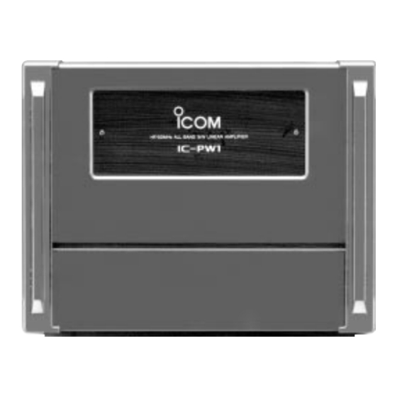
Icom IC-PW1 Service Manual
Hf/50 mhz all band linear amplifier
Hide thumbs
Also See for IC-PW1:
- Service manual addendum (201 pages) ,
- Service manual (178 pages) ,
- Instruction manual (24 pages)
Table of Contents
Advertisement
Advertisement
Table of Contents

Related Manuals for Icom IC-PW1


Summary of Contents for Icom IC-PW1
- Page 1 HF/50 MHz ALL BAND LINEAR AMPLIFIER iC-PW1...
-
Page 2: Ordering Parts
This service manual describes the latest service information for HIGH VOLTAGE! NEVER touch the antenna con- the IC-PW1 HF/50 MHz ALL BAND LINEAR AMPLIFIER at nector or the power supply section in the linear amplifier the time of publication. while connecting the IC-PW1 to an AC outlet. -
Page 3: Table Of Contents
TABLE OF CONTENTS SECTION 1 SPECIFICATIONS SECTION 2 INSIDE VIEWS SECTION 3 CIRCUIT DESCRIPTION LINEAR AMPLIFIER CIRCUITS ..................3 - 1 ANTENNA TUNER CIRCUITS ................... 3 - 2 PROTECTION CIRCUITS ....................3 - 3 POWER SUPPLY CIRCUITS .................... 3 - 4 PORT ALLOCATIONS ....................... - Page 4 SECTION 1 SPECIFICATIONS GENERAL • Frequency range : 1.800–1.999 MHz 3.500–3.999 MHz 4.630 MHz 7.000–7.300 MHz 10.100–10.150 MHz 14.000–14.350 MHz 18.068–18.168 MHz 21.000–21.450 MHz 24.890–24.990 MHz 28.000–29.700 MHz 50.000–54.000 MHz The USA version can only be used the antenna tuner on the 24–28 MHz bands. •...
-
Page 5: Inside Views
SECTION 2 INSIDE VIEWS FRONT UNIT SW BOARD ANT-SW UNIT JACK1 UNIT FRONT SIDE LOWPASS FILTER POWER UNIT FILTER UNIT PA-4 BOARD COMBINR UNIT PA-2 BOARD PA-3 BOARD SPLITR UNIT PA-1 UNIT 2 - 1... - Page 6 TUNER UNIT C-NET BOARD H-NET BOARD DET BOARD CONNECT BOARD FRONT SIDE MAIN UNIT L-NET BOARD 2 - 2...
-
Page 7: Linear Amplifier Circuits
SECTION 3 CIRCUIT DESCRIPTION 3-1 LINEAR AMPLIFIER CIRCUITS 3-1-3 POWER AMPLIFIER CIRCUITS (PA1–4 BOARDS) 3-1-1 EXCITER INPUT SWITCHING CIRCUIT The power level divided signal from the SPLITR unit is (SPLITR UNIT) amplified at the power amplifier circuit (Q1a/b). The ampli- The applied signal from the exciter (transceiver) is passed fied signal is applied to the COMBINR unit. -
Page 8: Antenna Tuner Circuits
2-step (3-step for the 50 MHz band) Chebyschev low-pass (2) Reactance components detector filters are adopted, to obtain –60 dB or less higher harmon- Reactance components are picked up by comparing the ic emissions for all HF bands or –70 dB or less for the 50 phase of the RF current and RF voltage. -
Page 9: Protection Circuits
(JACK2 unit; J7). condition, tuning relays select the capacitors and coils. (2) I -ALC In the IC-PW1, internal power supply voltage (I ) is used for -ALC. The power supply voltage (I ) is amplified at the op- 3-3 PROTECTION CIRCUITS amplifier (IC1c), then applied to the ACC2 socket. -
Page 10: Power Supply Circuits
3-5 PORT ALLOCATIONS 3-3-4 TEMPERATURE DETECTOR CIRCUIT 3-5-1 EXPANDER IC (SWITCH BOARD; IC1) (SPLITR AND MAIN UNITS) The temperature detector circuit detects the temperature of Port the heatsink for final FETs and controls amplifying operation. Description number name Outputs INPUT “1” LED control signal. A thermistor (SPLITR unit;... - Page 11 3-5-3 EXPANDER IC (SWITCH BOARD; IC3) 3-5-5 SHIFT REGISTER IC (SWITCH BOARD; IC7) Port Port Description Description number name number name Outputs “50” LED control signal. Input port for the antenna switching 50ML High: While “50” LED is ON. signal. Low: When “ANT”...
- Page 12 3-5-6 CPU (MAIN UNIT; IC26) Port Port Description Description number name number name Input port for the forward power volt- Outputs ANT1 select signal to RL4 on age from IC2 (pin 1). ANT1 the ANT-SW unit. Low : When ANT1 is selected. Input port for the reflected voltage from IC2 (pin 7).
-
Page 13: Adjustment Procedures
Shorten inner and outer plugs dummy load RF power meter 1500 W/50 Ω Coaxial cable to the ANT1 connector INPUT1 Coaxial cable EXCITER RF OUT IC-PW1 Ground AC outlet [USA] : 100–120/220–240 V [EUR] and [EUR-1] : 230 V 4 - 1... -
Page 14: Pa And Front Units Adjstment
4-2 PA AND FRONT UNIT ADJUSTMENT Idling current must be taken out the PA unit from the main body. ADJUSTMENT MEASUREMENT POINT ADJUSTMENT ADJUSTMENT CONDITION VALUE UNIT LOCATION UNIT ADJUST IDLING • [POWER] switch : OFF Front Connect 100 mA CURRENT •... - Page 15 • Idling current adjustment Front side (after removed front panel) ALC and I meter check point Ammeter Connect the lead of L6 to ground PA1–PA4 boards FRONT SIDE • Idling current pre-setting • Idling current adjustment PA-1 BOARD PA-2 BOARD Connect the lead of L5 PA-3 BOARD to ground...
-
Page 16: Main Unit Adjustment
IC-736 Verify BASIS VOLT- IC-736, and then connect to J18 shows “SET”. on the MAIN unit of IC-PW1. • Connect [ANT1] connector of IC- 736 to [INPUT1] connector of IC- PW1. • Connect a 150 Ω dummy load to [ANT1] connector of IC-PW1. - Page 17 FILTER UNIT • Tuner basis voltage adjustment FRONT SIDE MAIN UNIT Disconnect J5 from here Bottom view of IC-736 Connect J5 on the tuner unit of IC-736 to here MAIN unit of IC-PW1 Tuner basis voltage pre-setting 4 - 5...
- Page 18 MAIN UNIT ADJUSTMENT (Continued) ADJUSTMENT MEASUREMENT POINT ADJUSTMENT ADJUSTMENT CONDITION VALUE UNIT LOCATION UNIT ADJUST • Input AC voltage : 200 V Controller [METER-2] Set [ALC] meter to REAR ALC adj1 POWER SET (HF BAND, • METER-1 : [P ] scale center as below: panel AC 200 V,)
-
Page 19: Rear Panel
Rear panel INPUT1 ANT4 ANT3 ANT2 ANT1 INPUT2 ACC-2 ALC2 SEND2 ACC-1 ALC1 SEND1 EXCITER 1&2 CONTROLLER REMOTE ALC adj2 REMOTE ALC adj1 ALC adj1 • Power set adjustment for HF band • P meter set adjustment FRONT SIDE MAIN UNIT MAIN unit Power set adjustment for 50 MHz band... - Page 20 MAIN UNIT ADJUSTMENT (Continued) ADJUSTMENT MEASUREMENT POINT ADJUSTMENT ADJUSTMENT CONDITION VALUE UNIT LOCATION UNIT ADJUST • Connect a DC ammeter to the Controller [METER-1] Set [I ] meter to a half MAIN “HV” line between power supply value of connecting unit and PA unit.
- Page 21 • I ALC and I meter adjustment Front side (after removed front panel) ALC and I meter check point Ammeter • I ALC adjustment load-resistor Front side (after removed front panel) Ammeter ALC check point Front side (after removed front panel) ALC check point Ammeter 4 - 9...
-
Page 22: Parts List
SECTION 5 PARTS LIST [MAIN UNIT] [MAIN UNIT] ORDER ORDER DESCRIPTION DESCRIPTION 1110001340 S.IC NJM3403AM-T1 1790000620 S.DIODE MA77 (TX) 1110000960 S.IC NJM4558M-T1 1790000620 S.DIODE MA77 (TX) 1110000960 S.IC NJM4558M-T1 1730000680 S.ZENER RD4.7M-T2B2 1110000960 S.IC NJM4558M-T1 1730000680 S.ZENER RD4.7M-T2B2 1180001070 S.IC TA7805F (TE16L) 1790001640 S.DIODE 1SS373 (TPH3) - Page 23 [MAIN UNIT] [MAIN UNIT] ORDER ORDER DESCRIPTION DESCRIPTION 6200003260 S.COIL NL 322522T-101J 7030003690 S.RESISTOR ERJ3GEYJ 124 V (120 kΩ) 6180000990 COIL LAL 04NA 101K 7310002740 S.TRIMMER RV-150 (RH03A3A14X0FC) 103 6200003950 S.COIL HF50ACC 322513-T 7310002580 S.TRIMMER RV-108 (RH03A3A15X05A) 104 6200003950 S.COIL HF50ACC 322513-T 7030003560 S.RESISTOR ERJ3GEYJ 103 V (10 kΩ)
- Page 24 [MAIN UNIT] [MAIN UNIT] ORDER ORDER DESCRIPTION DESCRIPTION R110 7030003560 S.RESISTOR ERJ3GEYJ 103 V (10 kΩ) R201 7030003720 S.RESISTOR ERJ3GEYJ 224 V (220 kΩ) R111 7030003560 S.RESISTOR ERJ3GEYJ 103 V (10 kΩ) R202 7030003720 S.RESISTOR ERJ3GEYJ 224 V (220 kΩ) R112 7030003640 S.RESISTOR ERJ3GEYJ 473 V (47 kΩ)
- Page 25 [MAIN UNIT] [MAIN UNIT] ORDER ORDER DESCRIPTION DESCRIPTION 4030011600 S.CERAMIC C1608 JB 1C 104KT-N C227 4030008920 S.CERAMIC C1608 JB 1C 473K-T-A 4030011600 S.CERAMIC C1608 JB 1C 104KT-N C228 4030006860 S.CERAMIC C1608 JB 1H 102K-T-A 4030011600 S.CERAMIC C1608 JB 1C 104KT-N C229 4030006860 S.CERAMIC C1608 JB 1H 102K-T-A...
- Page 26 [FILTER UNIT] [FILTER UNIT] ORDER ORDER DESCRIPTION DESCRIPTION 6180000990 COIL LAL 04NA 101K 4040000150 BARRIER UAT 05X 472K 6140001000 COIL LR-123 4040000150 BARRIER UAT 05X 472K 6180000990 COIL LAL 04NA 101K 4040000150 BARRIER UAT 05X 472K 6110003440 COIL LA-538 4030004740 S.CERAMIC C2012 JB 1H 472K-T-A 6110003460 COIL LA-537...
- Page 27 [FILTER UNIT] [SPLITR UNIT] ORDER ORDER DESCRIPTION DESCRIPTION 8600035753 M.OTHER EX1900 P01*J01FI-3 1180001250 S.IC TA7808F (TE16L) 8970022640 M.OTHER EX1900 1.5D COAXIAL (1)/FI 8970022650 M.OTHER EX1900 TEFLON COAXIAL (1)/FI 8970023250 M.OTHER EX1900 J LEAD SET (1)/FI 1750000270 S.DIODE 1SS301 (TE85R) 1750000270 S.DIODE 1SS301 (TE85R) 1790000490 S.DIODE HSM88AS-TR...
- Page 28 [SPLITR UNIT] [PA-1 BOARD] ORDER ORDER DESCRIPTION DESCRIPTION 0910048784 PCB B 4890D 4010005740 CERAMIC HM60SJ SL 560J 500V 9034901004 TUBE D=1.0, L=10 mm 4030011790 S.CERAMIC GRM44-1 Y5V 684Z 100PT 9050409902 TUBE D=1.0, L=15 mm 4030011790 S.CERAMIC GRM44-1 Y5V 684Z 100PT 9019000830 TUBE PLASTIC TUBE D=6.0, L=750 mm 4030006480 S.CERAMIC...
- Page 29 [PA-2 BOARD] [PA-3 BOARD] ORDER ORDER DESCRIPTION DESCRIPTION 7310003180 TRIMMER EVN-2ACA00 B24 (203) 6110001730 COIL LA-262 ERX3SJ 1R8 (1.8 Ω) 7070000900 RESISTOR 6140003040 COIL LR-322B ERX3SJ 1R8 (1.8 Ω) 7070000900 RESISTOR 6140002590 COIL LR-296 ERG3SJ 561 (560 Ω) 7070000960 RESISTOR 6140000720 COIL LR-95 ERG3SJ 270 (27 Ω)
-
Page 30: Tuner Unit
[PA-4 BOARD] [PA-4 BOARD] ORDER ORDER DESCRIPTION DESCRIPTION 1750000270 S.DIODE 1SS301 (TE85R) 6910011330 TERMINAL OT-009 M3 1750000270 S.DIODE 1SS301 (TE85R) 6910011330 TERMINAL OT-009 M3 1750000270 S.DIODE 1SS301 (TE85R) 6910000640 BEAD FSOH090RN 1750000270 S.DIODE 1SS301 (TE85R) 0910048706 PCB B 4884F 6110001730 COIL LA-262 6140003040 COIL LR-322B... - Page 31 [DET BOARD] [CONNECT BOARD] ORDER ORDER DESCRIPTION DESCRIPTION 7030009330 RESISTOR ERJ1WYJ300H 4030010210 S.CERAMIC C3216 JB 1C 105M-T-A 7030003560 S.RESISTOR ERJ3GEYJ 103 V (10 kΩ) 4030010210 S.CERAMIC C3216 JB 1C 105M-T-A 7030003800 S.RESISTOR ERJ3GEYJ 105 V (1 MΩ) 4030010210 S.CERAMIC C3216 JB 1C 105M-T-A 7030003560 S.RESISTOR ERJ3GEYJ 103 V (10 kΩ) 4030010210 S.CERAMIC...
- Page 32 [H-NET BOARD] [C-NET BOARD] ORDER ORDER DESCRIPTION DESCRIPTION 6180000990 COIL LAL 04NA 101K 4040000150 BARRIER UAT 05X 472K 6180000990 COIL LAL 04NA 101K 4040000150 BARRIER UAT 05X 472K 6110003410 COIL LA-535 4040000150 BARRIER UAT 05X 472K 6110003400 COIL LA-534 4040000150 BARRIER UAT 05X 472K 6110003510 COIL LA-544...
- Page 33 [JACK1 UNIT] [ANT-SW UNIT] ORDER ORDER DESCRIPTION DESCRIPTION 6200003260 S.COIL NL 322522T-101J 8600035743 M.OTHER EX1900 P01*J01AN-SW-3 6200003260 S.COIL NL 322522T-101J 6200003260 S.COIL NL 322522T-101J 6200003260 S.COIL NL 322522T-101J 6910011340 TERMINAL OT-010 M3 6200003260 S.COIL NL 322522T-101J 6910011340 TERMINAL OT-010 M3 6200003260 S.COIL NL 322522T-101J 0910048716 PCB...
- Page 34 [SW BOARD] [SW BOARD] ORDER ORDER DESCRIPTION DESCRIPTION 1750000270 S.DIODE 1SS301 (TE85R) 4030011600 S.CERAMIC C1608 JB 1C 104KT-N 1750000270 S.DIODE 1SS301 (TE85R) 4030011600 S.CERAMIC C1608 JB 1C 104KT-N 1750000290 S.DIODE 1SS300 (TE85R) 4030011600 S.CERAMIC C1608 JB 1C 104KT-N 1750000290 S.DIODE 1SS300 (TE85R) 4030011600 S.CERAMIC C1608 JB 1C 104KT-N...
-
Page 35: Mechanical Parts And Disassembly
8810003360 Set screw C M3 × 6 8930042540 1900 Jack plate MP85 MP10 8510011342 1900 A-filter case-2 MP86 8310044320 IC-PW1 FCC sirial number seal [USA] MP11 8510011360 1900 A-filter cover 8310039900 IC-PW1 FCC sirial number seal EUR] MP12 8310039540 1900 hole plate 8310046130 IC-PW1 FCC sirial number seal [EUR-1] ×... - Page 36 MP66 MP65 MP66 ANT-SW UNIT [JACK-1 UNIT] CHASSIS PARTS ORDER REF NO. DESCRIPTION QTY. MP65 MP21 6450001590 Connector TCS5073-17-4151 6450001130 Connector JPJ2042-01-110 MP84 6450000140 Connector HSJ0807-01-010 MP67 MP85 MP21 6450001590 Connector TCS5073-17-4151 MP37 6450001130 Connector JPJ2042-01-110 MP54 6450000140 Connector HSJ0807-01-010 MP68 WS1 (AN) MP31...
- Page 37 MP15 MP15 MP19 MP16 SW BOARD MP13 MP18 MP17 MP11 MP16 FRONT UNIT MP17 MP18 MP14 MP16 MP45 (CH) MP13 MP19 MP12 MP20 MP17 MP80 (CH) MP11 WS1 (CH) MP45 (CH) MP12 MP81 (CH) MP26 (CH) MP12 MP45 (CH) MP14 FILTER UNIT MP45 (CH) MP20...
- Page 38 6-2 FRONT UNIT DISASSEMBLY 6-3 FILTER UNIT DISASSEMBLY [FRONT UNIT] [FILTER UNIT] ORDER ORDER QTY. QTY. REF NO. DESCRIPTION REF NO. DESCRIPTION 5080000380 Lamp HRS-4160A-H9 L150 6910011330 Terminal OT-009 M3 5080000380 Lamp HRS-4160A-H9 L150 6910011330 Terminal OT-009 M3 6910011040 Tube A-4210-G20 6910011330 Terminal OT-009 M3 6910011040 Tube A-4210-G20 6910011330 Terminal OT-009 M3...
- Page 39 6-4 POWER UNIT DISASSEMBLY [PA UNIT] [PA-1 BOARD] ORDER ORDER ORDER QTY. QTY. QTY. REF NO. REF NO. DESCRIPTION DESCRIPTION REF NO. DESCRIPTION 8900006990 Cable OPC-683 (N:10 L:110) 6510017920 Connector 1811P342 8900007360 Cable OPC-711 (N:10 L:250) 6510003390 Connector B03B-EH-S 8900006990 Cable OPC-683 (N:10 L:110) 6510003080 Connector RT01T-1.0B 8900007360 Cable OPC-711 (N:10 L:250) 6910011330 Terminal OT-009 M3...
- Page 40 J2 (CH) J1 (CH) PA UNIT WS3 (CH) MP11 MP12 MP11 MP16 MP11 PA-2 BOARD W15 (CH) MP10 MP11 MP11 SPLITR UNIT MP11 MP10 MP106 (CH) MP11 MP13 MP11 MP17 MP11 W16 (CH) MP22 PA-1 BOARD PA-4 BOARD W18 (CH) MP21 PA-3 BOARD MP14...
- Page 41 6-5 TUNER UNIT DISASSEMBLY [TUNER UNIT] TUNER UNIT MP20 ORDER REF NO. DESCRIPTION QTY. MP111 (CH) 4620000130 UV55 150pF 4620000130 UV55 150pF MP39 W21 (CH) H-NET BOARD 9019001020 Enpire tube MP111 (CH) 2710000460 Stepping motor MP28GA MP20 2710000460 Stepping motor MP28GA MP40 2710000630 Fan FBA08T12HC (w/beadscore) MP16...
- Page 42 [MAIN UNIT] [ACCESSORIES] ORDER ORDER REF NO. DESCRIPTION QTY. REF NO. DESCRIPTION QTY. 6510003080 Connector RT01T-1.0B 8900007580 Cable OPC-730 6510003450 Connector B09B-EH-S 8900002260 Cable OPC-104 B 6510003480 Connector B12B-EH-S 8900002270 Cable OPC-125 B 6510003410 Connector B05B-EH-S 8900007290 Cable OPC-718 6510003490 Connector B13B-EH-S 6510020330 Terminal 5.5-5 pin 6510003410 Connector B05B-EH-S 6910010480 DL-7C OR-31-15-19H [USA], [EUR]...
-
Page 43: Semi-Conductor Information
SECTION SECTION 7 PARTS LIST SEMI-CONDUCTOR INFORMATION 7-1 TRANSISTOR AND FET’s 7-2 DIODES NAME SYMBOL INSIDE VIEW NAME SYMBOL INSIDE VIEW 1SS300 2SA1588-GR 2SA1586-Y 1SS301 2SB1119S 2SB1123S 2SB1132R 1SS315 1SS373 D2FS4-4063 2SC2714-O 2SC4116-GR HSM88AS-TR 2SK302-Y MA77 2SK515-T1B MA8051-M RD4.7M-T2B2 DTC114EE RD5.1M-T2B2 DTC144EE 7 - 1... -
Page 44: Board Layouts
SECTION 8 BOARD LAYOUTS 8-1 ANT- SW UNIT TO MAIN UNIT J9 BOARD TOUT CHASSIS UNIT TO ANT1 TO ANT4 TO ANT3 TO ANT2 8-2 C-NET BOARD TO DET BOARD TO DET BOARD TO DET BOARD CP10 CP11 COUT MAIN UNIT MAIN UNIT VHCI CI3B... -
Page 45: L-Net Board
8-3 L-NET BOARD H-NET BOARD MAIN UNIT 8-4 H-NET BOARD TO MAIN UNIT L-NET 20mm BOARD TO C-NET BOARD 8 - 2... -
Page 46: Connect Board
8-5 CONNECT BOARD MOTOR STEPPER TO MAIN UNIT J14 MOTOR STEPPER 8 - 3... -
Page 47: Combinr Unit
8-6 COMBINR UNIT TO MAIN UNIT J17 W5, W6 W3, W4 W1, W2 PAO1 PAO2 PAO4 PAO3 TO PA1 TO PA2 TO PA4 TO PA3 BOARD BOARD BOARD BOARD TO FILTER UNIT 8 - 4... -
Page 48: Splitr Unit
8-7 SPLITR UNIT TO MAIN UNIT J10 TO PA1 BOARD J3 TO PA BOARD TEMP PA2-J1 DRIV PA1-J1 PA3-J1 PA4-J1 TO CHASSIS TO CHASSIS FILTER UNIT 8 - 5... -
Page 49: Pa Unit
8-8 PA UNIT TO PA4 BOARD J3 TO PA3 BOARD J3 TO PA2 BOARD J3 NONE – TO PX-1981 (OPTION) (each PA bords) (each PA bords) (each PA bords) PA1 BOARD J4 PA4 BOARD J4 PA3 BOARD J4 PA2 BOARD J4 TO PA-2 BOARD TO PX-1981... - Page 50 8-9 DET BOARD TO C-NET BOARD COUT CP11 CP10 TOUT TO ANT-SW UNIT TO FILTER UNIT TO C-NET BOARD TO MAIN UNIT J6 8 - 7...
- Page 51 8-10 JACK-1 UNIT EXCITER REMOTE SEND1 ALC1 ACC1 REMOTE SEND2 ALC2 ACC2 1 & 2 ADJ.1 adj.2 TO MAIN UNIT J2 TUNER UNIT 8 - 8...
- Page 52 8-11 SW BOARD ¡ ¡ TOP VIEW The combination of this page and the next page shows the unit layout in the same configuration as the actual P.C. Board. POWER TRANSMIT INPUT TEMP METER-1 METER-2 TUNER AMP/PROTECT DOWN AUTO 8 - 9...
- Page 53 ¡ ¡ BOTTOM VIEW The combination of this page and the previous page shows the unit layout in the same configuration as the actual P.C. Board. DATA DATA DATK DATK MAIN UNIT DATA2 DATA2 STR2 STR2 DS-2 DS-1 FRONT UNIT DS1 LAMP DS2 LAMP 8 - 10...
- Page 54 8-12 FILTER UNIT The combination of this page and the next page shows the unit layout in the same configuration as the actual ¡ ¡ TOP VIEW TO COMBINR UNIT P.C. Board. SPLITER TO MAIN UNIT J8 UNIT J8 8 - 11...
- Page 55 ¡ ¡ BOTTOM VIEW The combination of this page and the previous page shows the unit layout in the same configuration as the actual P.C. Board. TO TUNER UNIT (DET BOARD) 8 - 12...
- Page 56 TO SPLITR UNIT TO SPLITR UNIT TO TUNER UNIT TO TUNER UNIT TO TUNER UNIT TO TUNER UNIT (DET BOARD) (C-NET BOARD) (L-NET BOARD) (H-NET BOARD) 8-13 MAIN UNIT TOP VIEW ¡ ¡ FANV FANV TO JACK1 CP47 ALC2 ALC2 CI1B CP46 UNIT J9...
- Page 57 The combination of this page and the previous page shows the unit layout in the same configuration as the actual P.C. Board. BOTTOM VIEW ¡ ¡ 8 - 14...
- Page 58 SECTION 9 BLOCK DIAGRAM CHASSIS UNIT DET BOARD SPLITR UNIT FILTER UNIT ANT1 COUPLER COUPLER D15, D16: MBD701 CAP SW CAP SW D3,D4, VSWR DET RELAY RELAY D5,D6: MA77 –13V ANT2 IC2: MC10125L INPUT1 IC5: D11, D12: IC4: TA74AC112 PA UNIT TA79L05 MD701 D13, D14: 1SS286...
-
Page 59: Det Board
SECTION 10 VOLTAGE DIAGRAM 10-1 WIRING DIAGRAM 1 2 3 4 5 6 7 8 9 10 J4 PAI2 PAI2 ANT1 ANT1 TOUT W9,W10 TOUT W1, W2 W3,W4 PAO2 PAO2 PA2 BOARD –13R ANT2 ANT2 BOARD ANT3 COUT ANT3 CP10 CP11 FILTER COMBINR... - Page 60 10-2 SPLITER, PA AND COMBINR UNITS PA2 BOARD PAI2 PAI2 PAO2 FILTER UNIT W3, W4 TO FILTER UNIT LR-365 R3 50 R4 50 R5 50 0.68 R6 50 LR-119 LR-119 LR-123 PAO1 TO CHASSIS LR-211 22 p 68 p LR-119 56 p PA1 BOARD AE5343...
-
Page 61: Filter Unit
10-3 FILTER UNIT LA-537 LA-538 LA-537 C130 12 p COMBINR P3 TRU UNIT 50 MHz RL17 RL16 SPLITR UNIT 15 p RL15 VB-12TBU-UL3 VB-12TBU-UL3 AW3033 100 µH 12 p 12 p 12 p 50 MHz ON : 11.5 V C118 C119 C123 C120... -
Page 62: Pa Unit
10-4 PA UNIT 0.68 0.68 4.5 V 4.5 V TX: 2.6 V TX: 2.6 V 0.68 RX: 0 V 0.68 RX: 0 V PAO2 PAO1 COMBINR COMBINR LR-322B 0.68 LR-322B 0.68 UNIT J2 UNIT J1 0.68 MRF150 MP 0.68 MRF150 MP LR-95 LR-95 2.2 k... -
Page 63: Front Unit
10-5 FRONT UNIT Io SELET: 0 V Io SELET: 4.7 V Io UNSELECT: 3.2 V Io UNSELECT: 0 V TUNER ON: 0 V TUNER OFF: 3.2 V CL-200YG CL-200YG CL-200YG CL-200YG DTC114EE DTC114EE DTC114EE DTC114EE PROTECT ON 3.2 V OFF 3.2 V Vo METER ALC METER PROTECT ON... - Page 64 10-6 MAIN UNIT R155 C107 47 k 140 µS TX ON RX: 0.8 V 3.4 V C111 TX: 4.0 V IC28 DTC114EE TC4W66F 1SS373 RX: 4.7 V 50MF IC16D TX: 0 V CP41 1SS301 PD4069UBG D18 MA77 [USA] 0.6 V 1 2 3 4 R233 CP42...
- Page 65 C107 0.1 TX: 1.1 V L1 100 µH RX: 0 V L2 100 µH 140 µS FILTER TX ON L3 100 µH UNIT J1 3.4 V IC20 0.0047 0.0047 AMP. ON and TX: 13.2 V TC74AC393F OTHER: 0 V IC19 0.6 V FILTER TD62783AF...
- Page 66 10-6 MAIN UNIT R155 C107 0.1 47 k TX: 1.1 V L1 100 µH RX: 0 V 140 µS L2 100 µH TX ON L3 100 µH FILTER RX: 0.8 V UNIT J1 C111 3.4 V TX: 4.0 V IC28 IC20 DTC114EE 0.0047...
-
Page 67: Main Unit
10-7 TUNER UNIT TUNER UNIT AR39251 MORE THAN 50 MHz BAND : 13.0 V H-NET BOARD LESS THAN 50 MHz BAND : 0 V 50 MHz 100 µH LA-535 1SS53 0.0047 –5V TO FILTER UNIT AR39251 MA77 0.0047 100 µH 1SS286 0.0047 IC2A... - Page 68 ALC adj2 MORE THAN 50 MHz BAND : 13.0 V 10 k LESS THAN 50 MHz BAND : 0 V H-NET BOARD 100 µH REMOTE 0.0047 ALC 2 ALC2O 100 µH SEND2O & TUNER UNIT EXCITER SEND 2 0.0047 MORE THAN 24 MHz BAND : 13.0 V LESS THAN 24 MHz BAND : 0 V FANV 100 µH...
- Page 69 10-7 TUNER UNIT ALC adj2 TUNER UNIT AR39251 MORE THAN 50 MHz BAND : 13.0 V H-NET BOARD 10 k 50 MHz LESS THAN 50 MHz BAND : 0 V 100 µH REMOTE LA-535 1SS53 0.0047 –5V TO FILTER UNIT AR39251 ALC 2 MA77...
- Page 70 6-9-16, Kamihigashi, Hirano-ku, Osaka 547-0002, Japan Phone : 06 6793 5302 : 06 6793 0013 : http://www.icom.co.jp/world/index.html < > Corporate Headquarters Communication Equipment 2380 116th Avenue N.E., Bellevue, WA 98004, U.S.A. Himmelgeister Str. 100, D-40225 D sseldorf, Germany Phone : ( 425 ) 454-8155...
- Page 71 Count on us! A-5449MZ-S-1 © 1999 Icom Inc. 6-9-16, Kamihigashi, Hirano-ku, Osaka 547-0002, Japan...
Need help?
Do you have a question about the IC-PW1 and is the answer not in the manual?
Questions and answers