Table of Contents
Advertisement
Quick Links
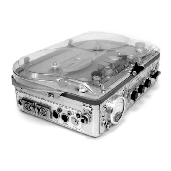
NAGRA 4.2
PORTABLE ANALOGUE AUDIO
TAPE RECORDER
INSTRUCTION MANUAL *
(KSA code No. 20 04 004 151)
Kudelski S.A.
NAGRA Tape Recorder Manufacturer
CH–1033 Cheseaux / SWITZERLAND
phone (021) 731 21 21
telex 459 302 nagr ch
Copyright reserved for all countries
telefax (021) 731 21 55
Orginally printed in Switzerland
February 1991 Edition
*this is an exclusive digital reprint and may only be used by Hunter College Students
Advertisement
Table of Contents

Related Manuals for Nagra NAGRA 4.2


Summary of Contents for Nagra NAGRA 4.2
- Page 1 NAGRA 4.2 PORTABLE ANALOGUE AUDIO TAPE RECORDER INSTRUCTION MANUAL * (KSA code No. 20 04 004 151) Kudelski S.A. NAGRA Tape Recorder Manufacturer CH–1033 Cheseaux / SWITZERLAND phone (021) 731 21 21 telex 459 302 nagr ch Copyright reserved for all countries...
- Page 2 Despite all these modifications, the machine remains remarkably simi- lar to the original. The Nagra 4.2 can be delivered in two different versions both of which are available in either NAB or CCIR equal- ization. These versions are: NQ–LSP...
- Page 3 24 21 26 27 28 29 20 30 11 31 5 34 22 6 1 3 2...
- Page 4 1. TAPE / DIRECT SWITCH (line and phones) 20. SPEED AND EQUALIZATION SELECTOR 2. TAPE / DIRECT (snap switch) 21. MOBILE TAPE GUIDE 3. POWER SELECTION SWITCH (external/bat- 22. PINCH ROLLER teries) 23. REWIND AND FAST FORWARD SWITCH 4. MAIN FUNCTION SELECTOR (six position rotary) 24.
-
Page 5: Controls: Description And Use
"OFF TAPE" signal otherwise it displays the "DIRECT" (EE) signal. 3. POWER SELECTION SWITCH (external / batteries) The Nagra 4.2 may be powered by either internal batteries or by an external source which may be selected using this switch. See also the Power Supply section of this manual. -
Page 6: Line & Playback Potentiometer
5. PINCHWHEEL LIFTER (stop + test only) 6. LEVEL CONTROL mic Input 2 7. LEVEL CONTROL mic Input 1 These are the main level controls for the two microphone inputs. 8. REFERENCE OSCILLATOR (push button) On the lower edge of the front panel, between the line and playback potentiometer and the mic 2 potentiome- ter. - Page 7 PILOT PLAYBACK This indicates the level of the pilot signal played back from the tape. PILOT FREQ This indicates on the + 4 to –4% scale of the modulometer, the frequency deviation as determined by the QFM frequency meter circuit (if fitted), between the pilot signal being recorded or played back and the 50/60 Hz reference.
-
Page 8: Speed And Power Indicator
NOTE: This only indicates the presence of a correct signal being fed to, or coming from the head, and does not guarantee correct recording of the signal. This should be checked by switching the modulometer to "PILOT" playback (this does not function in the "RECORD" mode). -
Page 9: Pinch Roller
TAPE DECK 20. SPEED AND EQUALIZATION SELECTOR This is a six position rotary switch permitting the selection of the speed and equalization of the 4.2 in both record and playback. Possible settings are: 3 3/4 (9.525 cm/s) 7 1/2 (19.05 cm/s) (38.10 cm/s) For each of these speed selections there are two possible positions labelled I and II;... - Page 10 The two rollers can be replaced by either the QTIM or QLEN tape measuring rollers. The QTIM is supplied in the place of the take–up reel tension roller as standard equipment. QLEN instead of QTIM is optional. (To be stated when ordering). 26.
- Page 11 1.3 CONNECTOR 36. MIKE 2 Input CCIR = Input signal Ground 2 + 3 = Balanced signal Input 37. MIKE 1 input Identical to No 36 above. NOTE: The microphone inputs are convertible into symmetrical and floating line inputs by installing, in place of the microphone preamplifiers, preamplifiers type QPM–6 and using the corresponding potentiometer to control the input level.
-
Page 12: Line Input
40. MIXER For connection to external mixing console. (connector type; T 3478 corresponding plug T 3475/1). 1. Input with fixed sensitivity, 560 mV to obtain 0 dB, input imped- ance 9 kΩ (2.5 Vpp to obtain + 4 dB). 2. –10 V stabilized voltage, maximum current 50 mA. Noise level < 5 µV rms. -
Page 13: Pilot And Clapper Inputs
600 Ω. When the "LINE AND PHONES" switch is in the position "TAPE", the line out- put voltage is 4.4 V into 600 Ω while playing back a tape recorded at 0 dB. The Nagra 4.2 can record at a level 4 dB higher than this, thus the maximum line output voltage will be 7 V. -
Page 14: Fixture For Carrying Strap/Handle
48. POWER PACK 6 pole connector for external power supply and pilot signal output. 1. – BATT: Negative pole of battery compartment. 2. + BATT: Positive pole of battery compartment. 3. PILOT PLAYBACK: Pilot playback output. 4. SPEED CORRECTION: Tape speed correction input. 5. -
Page 15: Power Supply
The Nagra 4.2 houses twelve "D" type 1.5 V cells having a maximum diameter of 33.5 mm and a length of between 59.5 and 62.5 mm. It is important to remember that corrosive material can leak out of flat batteries, causing severe damage to the recorder, and therefore it is recommended not to leave batteries in the machine during periods of storage. - Page 16 The position Volt/Cell is essentially designed to monitor the voltage of some accumulators which would be dam- aged it they were allowed to discharge below a certain value. This value is 1 V /Cell for certain manganese diox- ide alkaline accumulators. It is also possible to monitor the external power supply voltage.
-
Page 17: Operation
Tape Speed and Standard Selection The Nagra 4.2 is capable of running at three different speeds which can be selected by means of "SPEED AND EQUALIZATION" selector (20) on the top deck of the recorder between the two spools. - Page 18 Depending on the position of "TAPE / DIRECT" switch (1) it is possible to monitor either the input signal, or the "OFF TAPE" signal on the headphones output during the recording. This is possible because the Nagra 4.2 has separate heads for recording and playback (moving this switch will not affect the recording).
- Page 19 To wind a tape fast forward use switch (23) as for rewind. However, it is not necessary to open the pinch roller gate. The "FAST FORWARD" position of the toggle switch is only active when the main function selector is in the "PLAYBACK"...
- Page 20 The Line and Phones snap switch allows meter readings of the playback signal while recording. It always snaps back into the "DIRECT" position. Audio Inputs The Nagra 4.2 has 4 inputs: – microphone inputs –...
- Page 21 Measurement of Signal Level The Nagra 4.2 is equipped with a device for measuring the signal level. Normally, this is a modulometer, but a VU–meter is available on special request.
- Page 22 (QGX–3). If a recording is made with a pilot version of the Nagra 4.2 it is later possible, during playback, to lock the speed of the Nagra by means of the pilot synchronizer (QSLI) to an external reference signal. This means that provid- ing the "start"...
- Page 23 Synchronizing a Recorded Tape Check that the machine is fitted with the QSLI synchronizer circuit. This circuit is located on the right side of the battery compartment inside the machine. The circuit faces downwards, and has its front right corner cut away. Feed pilot input connector (44) with the reference signal either from the pilot out socket on the ATN–3 (for syn- chronization to mains) or from the machine to which the 4.2 is to be synchronized.
- Page 24 Speed Varier QSV–2 This is an external accessory for the Nagra 4.2. It is plugged into the ACC socket (39) on the left side of the recorder. It enables the speed to be varied manually up to ± 12% The QSV–2 is used for the following applica- tions: a) To transfer a tape whose pilot signal originated from a camera the speed of which was out of tolerance.
- Page 25 Output voltage from tape recorded on Nagra 4.2 L: 0.85 V nominal ±3 dB. The Nagra 4.2 fitted with a QSLI can be used to measure the playback pilot signal. 0.85 V corresponds to a meter deflection of 1 V on the scale calibrated from 0 to 2 V and normally used to measure the voltage per cell...
- Page 26 Pilot Connectors On the Nagra 4.2, the pilot playback signal is to be found on Power Pack connector (48) which is a 6 pin Tuchel socket located on the right side of the recorder. Pin No 2 is connected to the chassis and the output pilot signal is connected to pin No 3.
Need help?
Do you have a question about the NAGRA 4.2 and is the answer not in the manual?
Questions and answers