Table of Contents
Advertisement
Quick Links
Advertisement
Table of Contents

Related Manuals for Nagra NAGRA-V


Summary of Contents for Nagra NAGRA-V
-
Page 1: Operating Instructions
OPERATING INSTRUCTIONS REFERENCE MANUAL NAGRA-V (PN 2031 001 150) - Page 2 We guarantee the NAGRA V products of our own manufacture against any defect arising from faulty manufacture for a period of THREE years from the date of delivery.
-
Page 3: About This Manual
They are divided into different chapters listed below. All words or acronyms in this manual written in Bold Italic are all relating to the menus of the NAGRA V. Chapter 1... -
Page 4: Table Of Contents
CHAPTER I PARTS OF THE MACHINE INTRODUCTION ..............................2 EXPLANATION OF THE PARTS OF THE MACHINE.................... 3 LEFT SIDE PANEL ............................... 3 Extension Connector (1)........................... 3 RS 422 Connector (2)............................4 Microphone Input Connectors (3) ........................4 Microphone Powering Selectors (4)......................... 4 FRONT PANEL.............................. -
Page 5: Introduction
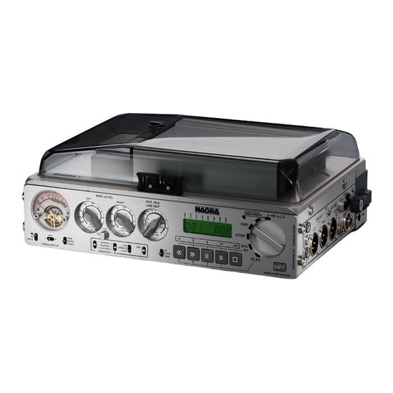
INTRODUCTION The NAGRA-V is a 24 bit solid state audio recorder / player using a removable hard drive as its storage medium (HDD). The information is stored as a digital linear FAT16/32 Broadcast Wave Format. Also equipped with an AES input and output as well as M/S technology and weighing less than 3.5 kg (including batteries), makes the NAGRA-V the most versatile tool available. -
Page 6: Explanation Of The Parts Of The Machine
External NRS left channel IN NOTE: If an external noise reduction system is connected to the NAGRA V then the two switches inside the machine need to be moved. These two switches S1 / S2 are on either side of the connector J12 on the box motherboard behind the modulometer. -
Page 7: Rs 422 Connector (2)
This is a standard 9-pin RS 422 symmetrical serial communication port for connection to the external world. The factory for test purposes uses this connector. For remote controlling the Nagra-V by PC or laptop, the same connector can also be used using the NV-COM software # 7031100000. -
Page 8: Front Panel
FRONT PANEL Light / Battery Switch (1) This three position switch has several functions which are depending on how it is used: Cloud position means modulometer and display backlights are ON Sun positon means modulometer and display backlights are OFF BATT. -
Page 9: Meter (2)
Attention: From the box motherboard 9131 300 000 B, when moving the 2 internal jumpers, the meter can be set before or after the Line Output potentiometer. This can only be done by a Nagra Service Center. See also chapter 4. -
Page 10: Sensitivity Selectors (6)
LFA / Speech / Flat (8) This is the filter selection switch. The filters available are the same as those on other NAGRA models and act on both the microphone and Line Inputs. The corresponding curves for the filters are shown:... -
Page 11: Reference Switch (9)
1 kHz (at 48/96 kHz, 919 Hz at 44.1/88.2 kHz), will be present at the outputs, if the NAGRA-V is in the test position. When the reference switch is held in the upper position during record, this signal will be recorded. No indication is given on the modulometer. -
Page 12: Shift Key (13)
The SHIFT key must be pressed (and kept pressed) in order to move through the menus on the LCD display on the front panel of the NAGRA V. When it is pressed the five grey transport keys operate using their shifted ARROW features. As soon as the SHIFT key is released then it will act as an ESC and the display will return to the main display screen chosen. -
Page 13: Lcd Display (14)
(AUX IN & LINE OUT) in the case that in the menu, the line potentiometer of the NAGRA V is set to the POT.SHIFT position. That is to say that it will adjust the input signal if the SHIFT key is kept pressed and it will adjust the OUTPUT signal if the SHIFT key is not pressed. -
Page 14: Right Side Panel
RIGHT SIDE PANEL Banana Output Connectors (1) This is the telephone output connection. It is a mono output fitted with a transformer with output impedance of 600 from 300 Hz to 5 kHz, and is used for connection to a standard switched telephone line. -
Page 15: Headphone Output Jack (4)
External Sync. or Video Input (6) If the NAGRA-V is fitted with the internal Time Code option then this is the connector where a video signal (PAL, NTSC, NTSC B/W, 75 Ohms internally loaded) or an external work clock can be imported. -
Page 16: Top Deck
Nagra-V. Attention: Never remove or insert the HDD from a Nagra-V if it is in the power on mode. Always shut down the machine, change the drive, put the power swicth on the drawer to on and turn on the Nagra-V.
Need help?
Do you have a question about the NAGRA-V and is the answer not in the manual?
Questions and answers