Table of Contents
Advertisement
Quick Links
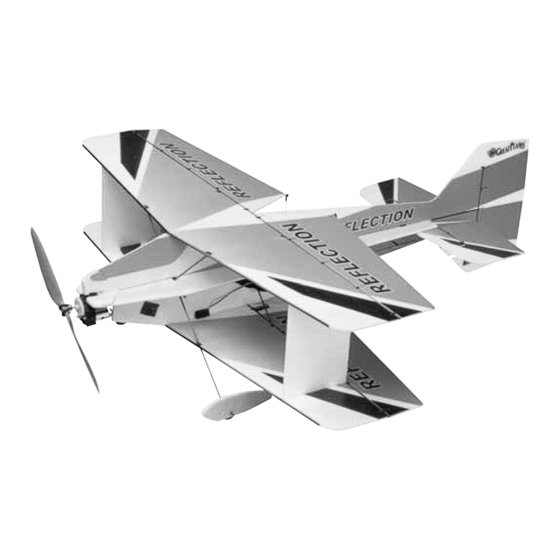
By Great Planes
Wingspan: 27.5 in [700mm]
Wing Area: 400 sq in [25.8 dm
Weight: 9.5 – 11 oz [270 – 310g]
Wing Loading: 4 oz/sq ft [10g/dm
Length: 31 in [785mm]
Radio: 4-channel w/3 micro servos and 10-Amp ESC
Power System: Included ElectriFly
or optional direct-drive RimFire
Great Planes
®
Model Manufacturing Co. guarantees this kit to be free from defects in both material and workmanship at the date of
purchase. This warranty does not cover any component parts damaged by use or modification. In no case shall Great Planes' liability
exceed the original cost of the purchased kit. Further, Great Planes reserves the right to change or modify this warranty without notice.
In that Great Planes has no control over the final assembly or material used for final assembly, no liability shall be assumed nor
accepted for any damage resulting from the use by the user of the final user-assembled product. By the act of using the user-assembled
product, the user accepts all resulting liability.
If the buyer is not prepared to accept the liability associated with the use of this product, the buyer is advised to return this
kit immediately in new and unused condition to the place of purchase.
To make a warranty claim send the defective part or item to Hobby Services at the address below:
Include a letter stating your name, return shipping address, as much contact information as possible (daytime telephone number, fax
number, e-mail address), a detailed description of the problem and a photocopy of the purchase receipt. Upon receipt of the package
the problem will be evaluated as quickly as possible.
READ THROUGH THIS MANUAL BEFORE STARTING
CONSTRUCTION. IT CONTAINS IMPORTANT WARNINGS
AND INSTRUCTIONS CONCERNING THE ASSEMBLY
AND USE OF THIS MODEL.
© Copyright 2005
INSTRUCTION MANUAL
2
]
2
]
™
T-370 motor with 5:1 ratio gearbox,
™
Brushless motor
3002 N. Apollo Dr., Suite 1
Champaign, IL 61822 USA
WARRANTY
Hobby Services
™
designed by Greg Ward
Champaign, Illinois
(217) 398-8970, Ext 5
airsupport@greatplanes.com
GPMZ0175 for GPMA1116 V1.0
Advertisement
Table of Contents

Subscribe to Our Youtube Channel
Related Manuals for electrifly reflection


Summary of Contents for electrifly reflection
-
Page 1: Instruction Manual
Weight: 9.5 – 11 oz [270 – 310g] Wing Loading: 4 oz/sq ft [10g/dm Length: 31 in [785mm] Radio: 4-channel w/3 micro servos and 10-Amp ESC Power System: Included ElectriFly ™ T-370 motor with 5:1 ratio gearbox, or optional direct-drive RimFire ™... -
Page 2: Table Of Contents
FlatOut 1. Even though the FlatOut Reflection ARF is small, Reflection ARF will be ready to tackle torque rolls, walls, lightweight and flies slowly, if it is not assembled and harriers, high-alpha rolling circles and more! An excellent... -
Page 3: Ama
DECISIONS YOU MUST MAKE Following are the order numbers for the R-124F receiver and compatible crystals: In the hands of a capable pilot the FlatOut Reflection ARF is Low Band High Band an impressive 3D performer. But for the FlatOut Reflection... -
Page 4: Speed Control
Great Planes Plan Protector (GPMR6167) or wax paper ™ Rest assured, the FlatOut Reflection ARF is capable of 3D flight with the included ElectriFly “stick-mount” motor and gearbox combination. But for pilots who always insist on upgrading and don’t mind spending a little extra money, the... -
Page 5: Kit Inspection
KIT INSPECTION Before starting to build, take an inventory of this kit to make sure it is complete, and inspect the parts to make sure they are of acceptable quality. If any parts are missing or are not of acceptable quality, or if you need assistance with assembly, contact Product Support. -
Page 6: Ordering Replacement Parts
ORDERING REPLACEMENT PARTS Replacement parts for the Great Planes FlatOut Reflection ARF are available using the order numbers in the Replacement Parts List that follows. The fastest, most economical service can be provided by your hobby dealer or mail-order company. -
Page 7: Build The Airplane
BUILD THE AIRPLANE A. Snap all of the hinges onto the carbon tube. Align the hinges with the slots. B. Coat both sides of one hinge with foam-safe CA where Assemble the Horizontal Tail it contacts the sides of the hinge slot. Rotate the hinge down into the slot. - Page 8 HOW TO GLUE THE TUBES TO THE CONTROL SURFACES ❏ 8. Insert a Z-bend clevis (A1) into a clip-hinge control Note: You may want to protect your work surface from horn (C1). excess glue. We recommend the use of Great Planes Plan Protector (GPMR6167) for this purpose.
-
Page 9: Assemble The Fuselage
Assemble the Fuselage ❏ 4. Position the servo mounts and fuselage joiners so that they align with the precut slots in the upper vertical fuselage half. ❏ ❏ 1. Cut the upper and lower vertical fuselage halves 5. Glue the fuselage tube to the upper vertical fuselage half. and the right and left horizontal fuselage halves free from their foam sheets. -
Page 10: Assemble The Wing
Assemble the Wing ❏ 9. Install a Z-bend clevis (A1) into a clip hinge control horn (C1). Using the 3 x 145mm [1/8" x 5-11/16"] rudder post tube as a guide, glue three clip hinges and the clip ❏ hinge control horn to the rudder. 1. - Page 11 ailerons. The control horns should protrude from the bottom of the ailerons (red and white side), and the offset Z-bend clevises should be on the outboard sides of the horns. Glue a control surface brace (E1) onto the roots of these two ailerons.
-
Page 12: Final Assembly
❏ ❏ 12. Installing them from the bottom of the bottom wing, 3. Slide the 2 x 358mm [5/64" x 14-1/16"] landing gear glue four supports into the slots in both sides of the top wing. legs through the landing gear supports in the front of the wings Two of the supports are at the leading edge (for the landing and fuselage. -
Page 13: Radio Setup
❏ 6. Glue the inner wheel pants to the outer wheel pants. ❏ Make sure to make one left and one right wheel pant. 10. Snap the ailerons onto the wing TE. Radio Setup ❏ 1. Remove the stock servo arms from all three of the servos. ❏... - Page 14 ❏ ❏ 5. Glue the aileron servo into a wing servo mount and 9. Install a Z-bend clevis (A1) into a single-sided servo arm glue the assembly into the bottom of the bottom wing with that fits your rudder servo. Install the arm onto the elevator the output shaft toward the rear.
- Page 15 ❏ ❏ 12. Slide a 1 x 149mm [3/64" x 5-7/8"] aileron link 15. Install the 1 x 380mm [3/64" x 15"] rudder pushrod pushrod into the clevises on each set of aileron link horns. the same way. Adjust the clevises until each set of ailerons are parallel. When you have the alignment correct, secure the pushrods with a drop of glue where the pushrod enters the clevis.
- Page 16 ❏ 5. If using the included prop, insert the larger of the two adapter rings (included in the propeller packaging) into the rear of the propeller hub. ❏ 2. Slide the motor mount block over the fuselage tube. Be certain the block is in the correct position so there will be down and right thrust.
- Page 17 Be careful not to change the built-in thrust angles. ❏ 4. If installing an ElectriFly RimFire motor, glue the included 3mm [1/8"] plywood firewall to the nose so that the center hole is centered on the fuselage tube. Note: If installing another brand of outrunner motor, you will need to cut your own firewall to match its mount pattern.
-
Page 18: Get The Model Ready To Fly
Set the Control Throws GET THE MODEL READY TO FLY To simplify setup, the high-rate (3D) control throws for this model are automatically set by the geometry of the included Check the Control Directions hardware. We do recommend, however, that you perform a quick check as described below to make sure the throws are set up correctly. -
Page 19: Balance The Model (C.g.)
you have determined the amount of weight required, it can Balance the Model (C.G.) be permanently attached. ❏ 4. IMPORTANT: If you found it necessary to add any weight, recheck the C.G. after the weight has been installed. More than any other factor, the C.G. (balance point) can have the greatest effect on how a model flies, and may determine whether or not your first flight will be Balance the Model Laterally... -
Page 20: Range Check
5) I will not fly my model unless it is identified with my name Range Check and address or AMA number, on or in the model. Note: This does not apply to models while being flown indoors. Ground check the operational range of your radio before the first flight of the day. -
Page 21: Flying
10. Range check your radio when you get to the flying site. FLYING Landing The FlatOut Reflection ARF is a great-flying model that flies Because this model is extremely lightweight, it slows rapidly smoothly and predictably. The FlatOut Reflection ARF does... - Page 22 NiCd, yellow for NiMH and green for For more information, log on at www.electrifly.com – and be Li-Ion or Li-Po cells. Jacks make it easy to hook up your pack amazed.
-
Page 23: Angle Templates
ANGLE TEMPLATES...
Need help?
Do you have a question about the reflection and is the answer not in the manual?
Questions and answers