Table of Contents
Advertisement
Quick Links
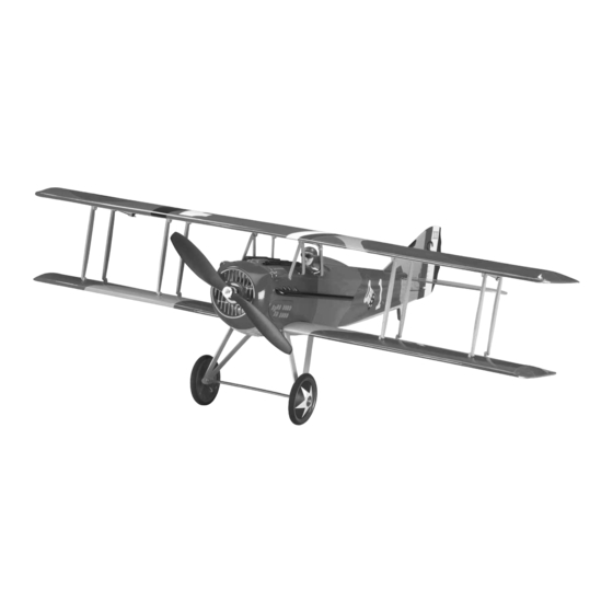
Wingspan: 34 in [865mm]
Wing Area: 390 sq in [25.2dm
2
]
Weight: 22.4 - 25.2 oz [635 – 715g]
Wing Loading: 8.3 – 9.3 oz/sq ft [25 – 28g/dm²]
Length: 27 in [685mm]
Radio: 4-Channel (minimum) with Micro Receiver, Four Micro Servos
™
™
Motor: ElectriFly
RimFire
28-30-950 Brushless
Propeller: Great Planes
®
10x3.5 Slo-Flyer Electric Propeller (GPMQ6655)
ESC: ElectriFly
™
SS-25
Battery: 11.1V, 1250mAh LiPo (must deliver 15 amps continuous)
Great Planes
®
Model Manufacturing Co. guarantees this kit to
be free from defects in both material and workmanship at the date
of purchase. This warranty does not cover any component parts
damaged by use or modifi cation. In no case shall Great Planes'
liability exceed the original cost of the purchased kit. Further,
Great Planes reserves the right to change or modify this warranty
without notice.
In that Great Planes has no control over the fi nal assembly or
material used for fi nal assembly, no liability shall be assumed nor
accepted for any damage resulting from the use by the user of
the fi nal user-assembled product. By the act of using the user-
assembled product, the user accepts all resulting liability.
If the buyer is not prepared to accept the liability associated
with the use of this product, the buyer is advised to return
READ THROUGH THIS MANUAL BEFORE STARTING CONSTRUCTION. IT CONTAINS IMPORTANT
INSTRUCTIONS AND WARNINGS CONCERNING THE ASSEMBLY AND USE OF THIS MODEL.
Entire Contents © Copyright 2008
INSTRUCTION MANUAL
WARRANTY
this kit immediately in new and unused condition to the place
of purchase.
To make a warranty claim send the defective part or item to Hobby
Services at the address below:
Include a letter stating your name, return shipping address, as
much contact information as possible (daytime telephone number,
fax number, e-mail address), a detailed description of the problem
and a photocopy of the purchase receipt. Upon receipt of the
package, the problem will be evaluated as quickly as possible.
Hobby Services
3002 N. Apollo Dr., Suite 1
Champaign, IL 61822 USA
Champaign, Illinois
(217) 398-8970, Ext 5
airsupport@greatplanes.com
™
GPMA1143Mnl V1.0
Advertisement
Table of Contents

Related Manuals for electrifly Spad XIII


Summary of Contents for electrifly Spad XIII
-
Page 1: Instruction Manual
3002 N. Apollo Dr., Suite 1 Champaign, IL 61822 USA In that Great Planes has no control over the fi nal assembly or material used for fi nal assembly, no liability shall be assumed nor accepted for any damage resulting from the use by the user of Include a letter stating your name, return shipping address, as the fi... -
Page 2: Table Of Contents
TABLE OF CONTENTS INTRODUCTION You’ll be proud to add the Great Planes SPAD XIII EP to your INTRODUCTION ............... 2 WWI hangar. This particular SPAD bears the markings of the AMA .................. 2 famous 94th Aero Squadron, distinguished by their famous SAFETY PRECAUTIONS .......... -
Page 3: Safety Precautions
6. You must check the operation of the model before every fl ight to insure that all equipment is operating and that the This is a partial list of items required to fi nish the SPAD XIII model has remained structurally sound. Be sure to check EP. -
Page 4: Battery Pack & Accessories
Optional Supplies & Tools in the Kit Contents list. Here is a list of optional tools mentioned in the manual that Great Planes Product Support will help you build the SPAD XIII EP. 3002 N. Apollo Drive, Suite 1 Champaign, IL 61822 ❏... -
Page 5: Kit Contents
If additional assistance is required for any reason contact To locate a hobby dealer, visit the Great Planes web site Product Support by e-mail at productsupport@greatplanes. at www.greatplanes.com. Choose “Where to Buy” at the com, or by telephone at (217) 398-8970. -
Page 6: Before You Begin
BEFORE YOU BEGIN ❏ 2. Using a 4-40 x 3/4" machine screw with a washer, temporarily install the lower wing to the fuselage. Fitting the lower wing will help you align the horizontal tail. Before you begin assembling your model, inspect it for ❏... -
Page 7: Install The Tail To The Fuselage
Install the Tail to the Fuselage A = A B = B ❏ 1. Remove the small block of wood protecting the upper structure of the aft fuselage. It may be glued in place, so a hobby knife may be needed. While you’re at it, trim away ❏... -
Page 8: Install The Motor & Esc
INSTALL THE MOTOR & ESC ❏ 7. Fit the three hinges into the slots of the vertical fi n. If the slots are too tight or the hinge won’t slide in all the way, you can use the back side of your hobby knife blade to dig them ❏... - Page 9 ❏ 7. Coat the underside of the battery tray with thin CA as shown. Apply a few thin lines of CA and dab up the excess CA with a paper towel. Allow the CA to dry. This will prepare the surface of the battery tray where the ESC and receiver will mount.
-
Page 10: Install The Elevator & Rudder Servos
❏ ❏ 10. Install the hook and loop battery strap on the battery 4. Install the rudder and elevator servos as shown with the tray from the bottom. servo leads facing aft. Do not run the leads forward. They will interfere with the operation of the motor. - Page 11 ❏ ❏ 7. Plug the elevator and rudder servos into their proper 9. Find the pushrod support and position it in the fuse as channels on the receiver. Plug the ESC into the receiver. shown. Do not glue it in place yet. Route the antenna and the Mount the receiver in the airplane as shown.
- Page 12 ❏ ❏ 14. Attach a control horn to the 1 x 550mm elevator 11. Locate two control horns. Use 220 grit sandpaper to lightly sand the tab portion of the horns. pushrod. Install the pushrod through the outermost hole of the horn.
-
Page 13: Prepare The Wings
PREPARE THE WINGS Install the Aileron Servos ❏ ❏ 4. As an alternative to gluing the servos in place, we have provided 7 x 7 x 12mm wood blocks that you may use to attach the servos to the servo bay covers. If you choose to use these, make sure that you align the servo as detailed in the previous step and then glue the blocks to the cover using ❏... -
Page 14: Install The Strut Mounts
❏ ❏ ❏ 2. Install the four strut mounts marked “B” in the top of the 7. Install a Screw-Lock pushrod connector in the outer hole of each aileron control horn. Position the connector lower wing in the LE slots. Use the sketch above to help you body on the outboard side of the horn. - Page 15 ❏ ❏ 2. Test fi t the cabane struts to the fuselage as shown. Use 5. Connect the aileron leads to the Y-harness. Use a a 1/16" [1.6mm] drill bit to drill a hole for the screw where drop of glue to attach the aileron Y-harness to the fuse side. shown.
-
Page 16: Install The Landing Gear
INSTALL THE LANDING GEAR ❏ 4. Install the 4 x 150mm axle tube. ❏ 1. Locate two 3 x 25mm fi ne thread machine screws and four 3mm nuts. Apply thread locking compound to each screw and install each to a wheel using one 3mm nut. To achieve the proper spacing, turn the nut until it contacts the wheel and then back it off 1/2 of a turn. -
Page 17: Install The Cowl & Propeller
2. Balance your propeller using the method described in the “Balance Propellers” section. The actual SPAD XIII was covered in fabric and had a “doped” fi nish brushed onto it. This gave it a semi-gloss or dull fi nish. Depending on how much you care to detail or personalize your SPAD, you may choose to replicate ™... -
Page 18: Get The Model Ready To Fly
GET THE MODEL READY TO FLY Center the Controls & Check the Control Directions WARNING: Once the battery is connected to the ESC, stay clear of the propeller! ❏ 1. Turn on the transmitter, center the trims, and move the throttle stick all the way down. -
Page 19: Set The Control Throws
NOTE: The throws are measured at the widest part of the control surfaces. To ensure a successful fi rst fl ight, fl y your SPAD XIII set up only according to the C.G. and control surface throws specifi ed in this manual. -
Page 20: Balance The Model (C.g.)
❏ This is where your model should balance for the fi rst 6. If additional weight is required, use Great Planes fl ights. Later, you may wish to experiment by shifting (GPMQ4485) “stick on” lead. A good place to add stick- the C.G. -
Page 21: Preflight
We use a Top Flite Precision Magnetic Prop Balancer™ 2) I will not fl y my model aircraft higher than approximately (TOPQ5700) in the workshop and keep a Great Planes 400 feet within 3 miles of an airport without notifying the Fingertip Prop Balancer (GPMQ5000) in our fl... -
Page 22: Check List
❏ in the proximity of full-scale aircraft. Where necessary, 7. Make sure all hinges are securely glued in place. ❏ an observer shall be utilized to supervise fl ying to avoid 8. Check the control horns for secure attachment to the having models fl... -
Page 23: Takeoff
If you do not have access to a smooth runway or short grass, the the power to control your descent rate. Blipping the throttle SPAD XIII can be hand launched. For the fi rst fl ight, have your may help you get a feel for where your throttle should be. - Page 24 Please photocopy to use the templates and ID tag. RUDDER HIGH 17˚ 90˚ ELEVATOR HIGH ELEVATOR/RUDDER 18˚ 13˚ AILERON HIGH AILERON LOW 20˚ 10˚...
Need help?
Do you have a question about the Spad XIII and is the answer not in the manual?
Questions and answers