Table of Contents
Advertisement
Quick Links
SPECIFICATIONS
SPECIFICATIONS
Wingspan:
Wingspan:
26.5 in
26.5 in
[675mm]
[675mm]
Wing Area:
Wing Area:
153 in
153 in
[9.9 dm
WARRANTY
Great Planes
®
Model Manufacturing Co. guarantees this kit to
be free from defects in both material and workmanship at the
date of purchase. This warranty does not cover any component
parts damaged by use or modification. In no case shall Great
Planes' liability exceed the original cost of the purchased kit.
Further, Great Planes reserves the right to change or modify this
warranty without notice.
In that Great Planes has no control over the final assembly or
material used for final assembly, no liability shall be assumed nor
accepted for any damage resulting from the use by the user of
the final user-assembled product. By the act of using the
user-assembled product, the user accepts all resulting liability.
If the buyer is not prepared to accept the liability associated
with the use of this product, the buyer is advised to return
READ THROUGH THIS MANUAL BEFORE STARTING CONSTRUCTION. IT CONTAINS IMPORTANT
INSTRUCTIONS AND WARNINGS CONCERNING THE ASSEMBLY AND USE OF THIS MODEL.
Entire Contents © Copyright 2010
Weight:
Weight:
2
2
Wing
Wing
2
]
Loading:
™
INSTRUCTION MANUAL
INSTRUCTION MANUAL
28–30 oz
28–30 oz
[790– 850 g]
[790– 850 g]
2
2
26 4– 28 2 oz/ft
26.4– 28.2 oz/ft
[81– 86 g /dm
2
]
this kit immediately in new and unused condition to the
place of purchase.
To make a warranty claim send the defective part or item to
Hobby Services at the address below:
Include a letter stating your name, return shipping address, as
much contact information as possible (daytime telephone
number, fax number, e-mail address), a detailed description of
the problem and a photocopy of the purchase receipt. Upon
receipt of the package the problem will be evaluated as quickly
as possible.
Length:
Length:
30.5 in [775mm]
30.5 in [775mm]
Radio:
Radio:
3-Channel, two micro servos,
3-Channel, two micro servos,
mini Rx
mini Rx
Motor,
Motor,
24-45-3790kV Ammo
24-45-3790kV Ammo
ESC
ESC
35A ESC HyperFlow
35A ESC, HyperFlow
56mm fan
Hobby Services
3002 N. Apollo Dr. Suite 1
Champaign IL 61822 USA
Champaign, Illinois
(217) 398-8970, Ext 5
airsupport@greatplanes.com
™
™
,
,
™
™
GPMA1800 Mnl
Advertisement
Table of Contents

Related Manuals for electrifly ElectriFly


Summary of Contents for electrifly ElectriFly
- Page 1 3002 N. Apollo Dr. Suite 1 Champaign IL 61822 USA In that Great Planes has no control over the final assembly or material used for final assembly, no liability shall be assumed nor Include a letter stating your name, return shipping address, as...
-
Page 2: Table Of Contents
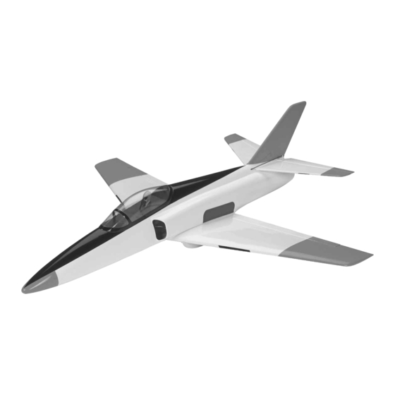
In a few cases the instructions may differ slightly from the photos. In those Thank you for purchasing the ElectriFly Evader EDF (electric instances the written instructions should be considered ducted fan) ARF. Prepare to be thrilled! Before you fl y your as correct. -
Page 3: Decisions You Must Make
PolyCharge4 is the Great Planes one more minute of motor run time for additional landing 12V 12A DC power supply (GPMP0901). attempts. • The Great Planes ElectriFly SS-35 35 Amp brushless ESC (GPMM1830) is also recommended. -
Page 4: Adhesives And Building Supplies
Stick-on segmented lead weights (GPMQ4485) • ALWAYS charge in a fi reproof location. ❏ Great Planes 1/8" x 3/8" [3.2 x 9.5mm] single-sided • NEVER trickle charge. adhesive foam tape (GPMQ4224) (Optional, for plywood • NEVER allow the battery temperature to exceed stand) 150°... -
Page 5: Kit Contents
Canopy/Hatch Set GPMA2883 Fuselage Set GPMA2884 To locate a hobby dealer, visit the Great Planes web site Bungee Launch Set GPMA2885 at www.greatplanes.com. Choose “Where to Buy” at the Decal GPMA2886 bottom of the menu on the left side of the page. -
Page 6: Assembly Instructions
Prepare the HyperFlow Fan Unit MOTOR & FAN INSTALLATION ❏ 1. Review steps 1 through 6 for Installing a Brushless Assemble the Stand Motor on pages 6 and 7 of the separate HyperFlow instruction manual, but don’t perform any of the steps yet. The included assembly/transport stand holds your Evader upside-down or upright. - Page 7 FAN ROTOR ADAPTER (BRASS) MOTOR SHAFT The adapter is all the way The adapter is not all the way on. down onto the motor shaft up ❏ 7. Test fi t only the fan rotor to the rotor adapter. If the head to the threads.
- Page 8 ❏ 15. Fit, then use thin CA to glue the included vacuum-formed front housing fl ange into the front of the fan unit. Make sure the cutout for the motor wires is also on the top of the unit (aligned with the wire hole in the cone adapter).
-
Page 9: Install The Fan Unit
Install the Fan Unit The fan unit is easy to install, but it takes a little fi nagling to get it through the intake hole. It’s a good idea to test fi t the fan without glue so you can make sure it fi ts properly. Once permanently installed, the fan unit will not be possible to remove. -
Page 10: Assemble The Wing
the cone adapter and around the outside of the cone in the ASSEMBLE THE WING fuselage. Reinstall the unit into the fuselage, making sure the cone adapter is properly engaged with the front of the cone. Wipe away excess epoxy by reaching down in through the Mount the Wing back of the tail cone with your fi... -
Page 11: Hook Up The Ailerons
Hook Up the Ailerons 12 – 13mm [7/16" – 1/2"] NOT CENTERED CENTERED THREADLOCK SCREW-LOCK CONNECTOR RETAINER Refer to this photo while hooking up the ailerons. ❏ 1. Same as was done for the plywood wing bolt plate, cut the covering from the top of the wing for the aileron servo ❏... -
Page 12: Install The Elevators
may not harden and could run out onto the fuselage when you turn it over. Allow the CA to fully harden—if you want to use CA accelerator apply only a fi ne mist from about 8" [200mm] away. ❏ 4. Turn the fuselage over and glue in the bottom of the stab with thin CA—again, don’t use too much! ❏... - Page 13 OUTER HOLE ❏ 5. Reattach the elevator to the stab and remove the pins from the hinges. With the pushrod connected to the horn, mount the horn to the top of the elevator by pushing the mounting plate tightly to the mounting posts up from the bottom.
-
Page 14: Hook Up The Elevators
Hook Up the Elevators FINAL ASSEMBLY ❏ 1. Now that the elevators have been hinged, free them up Mount the Receiver and Battery by moving them up and down several times. ❏ 1. Mount the receiver to the bottom of the fuselage just Refer to this photo while hooking up the elevators. - Page 15 ❏ 5. Sand a small bevel to the front of the top of the external battery plate. “HOOK” SIDE “LOOP” SIDE ❏ 3. To mount your battery with a strap, fi rst apply the rougher, “hook” side of the included adhesive-backed Velcro material to the plywood external battery plate and the ❏...
-
Page 16: Attach The Landing Skids
the skid is parallel with the center of the wing. Then, use a fi ne-point felt-tip pen to mark the outline of the skid onto the wing. ❏ 8. If not mounting your battery with a strap, simply apply the rougher, “hook” side of the included adhesive-backed Velcro material to the plywood battery plate in the fuselage and the softer, “loop”... -
Page 17: Apply The Hand Grips
Apply the Hand Grips The no-slip hand grips may seem unnecessary, but they really do assist when gripping the fuselage for bungee launching. The last thing you want is for the plane to slip out of your hands before you’re ready! ❏... -
Page 18: Get The Model Ready To Fly
These are the recommended control surface throws: GET THE MODEL READY TO FLY HIGH RATE LOW RATE Set the Control Throws Down Down To ensure a successful fi rst fl ight it is critical that the 1/4" 1/4" 3/16" 3/16" ELEVATOR Evader is set up according to the control throws specifi... -
Page 19: Balance The Model Laterally
To fi nd out how much weight will be required batteries may not reach their full capacity and you may be lay segments of Great Planes Stick-On Lead (GPMQ4485) fl ying with batteries that are only partially charged. on the nose over the location where it will be placed inside or on the tail until you can get the model to balance. -
Page 20: Assemble The Bungee Launch
Assemble the Bungee Launch ❏ 1. Loop one end of the rubber tubing and insert it through one of the metal rings. ❏ 5. Bring the loop in back over itself and the ring. You’ll have to pull the rest of the cord up all the way through the loop before tightening it around the ring. -
Page 21: Checklist
AMA SAFETY CODE ( CHECK LIST EXCERPTS Read and abide by the following excerpts from the Academy During the last few moments of preparation your mind may of Model Aeronautics Safety Code. For the complete Safety be elsewhere anticipating the excitement of the fi rst fl ight. Code refer to Model Aviation magazine, the AMA web site or Because of this, you may be more likely to overlook certain the Code that came with your AMA license. -
Page 22: Mount The Wing
Mount the Wing Hand Launch Mount the wing with the two 3 x 15mm Phillips screws and fl at washers. With the canopy off, don’t forget to connect the aileron servo to the receiver through the cockpit. Ground Check and Range Check Always perform an operational ground check of your radio before the fi... -
Page 23: Bungee-Launch
Bungee Launch The great thing about the bungee launch is its consistency—you should be able to get a perfect bungee-launch every time. Also, bungee-launching the Evader by your self is much easier than hand-launching it by your self, but for the fi rst one or two, it’s still a good idea to have an assistant launch it for you so your hands will be ready on the transmitter. -
Page 24: Flying
down. It will still be going fast so make sure your landing is Flight over smooth ground so it doesn’t catch the nose or a wing tip. The Evader never really fl ares like a regular plane—it Once the Evader begins climbing, simply fl y straight out, just loses fl...
Need help?
Do you have a question about the ElectriFly and is the answer not in the manual?
Questions and answers