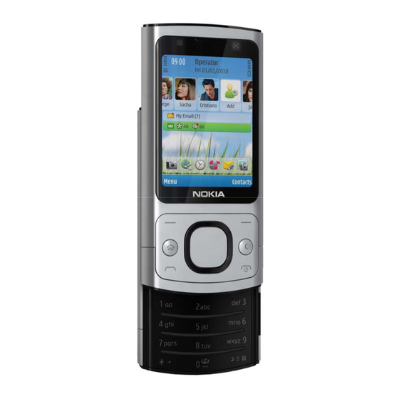
Nokia 6700 Slide Service Manual
Hide thumbs
Also See for 6700 Slide:
- User manual (69 pages) ,
- Manual del usuario (64 pages) ,
- Service schematics (11 pages)
Table of Contents
Advertisement
Quick Links
1
SERVICE MANUAL
Level 1&2
RM-576 / RM-577
Transceiver characteristics
Band:
RM-576:
• WCDMA 900/1900/2100 (VIII, II, I)
• GSM 850/900/1800/1900
RM-577:
• WCDMA 850/1900/2100 (V, II, I)
• GSM 850/900/1800/1900
Display:
320 x 240 QVGA 2.2" 16M colors TFT
Camera:
Main camera: 5 megapixels (2592 x 1944) 3x digital zoom
Secondary camera: 320 x 240
Operating System:
S60 3rd Edition Feature Pack 2 (S60 3.2.3) Symbian OS 9.3
Connections:
• Bluetooth 2.0 EDR, A2DP
• 2.5 mm AV connector
• High-Speed 2.0 Micro-USB connector
• Micro SD card (2 GB in sales package)
• WLAN is not supported
Transceiver with BL-4C battery pack
Talk time
GSM:
Up to 4 hours
WCDMA:
Up to 3 hours
Note:
Talk times are dependant on network parameters and
phone settings
Confidential | Copyright © 2010 Nokia | All rights reserved
Nokia 6700 Slide
RM-576 / RM-577
Service Manual Level 1&2
Standby
GSM:
Up to 300 hours
WCDMA:
Up to 250 hours
Version 2.0
Advertisement
Table of Contents

Related Manuals for Nokia 6700 Slide


Summary of Contents for Nokia 6700 Slide
- Page 1 Up to 4 hours Up to 300 hours WCDMA: WCDMA: Up to 3 hours Up to 250 hours Note: Talk times are dependant on network parameters and phone settings Confidential | Copyright © 2010 Nokia | All rights reserved Version 2.0...
-
Page 2: Table Of Contents
6. Battery information ..................................8 7. Exploded view ....................................9 8. Service devices .....................................10 9. Software update ..................................11 10. Disassembly instructions ..............................12 11. Assembly Hints ..................................21 12. Solder components ................................25 Confidential | Copyright © 2010 Nokia | All rights reserved Version 2.0... -
Page 3: Change History
New item added to the exploded view The purpose of this document is to help Nokia service levels 1 and 2 workshop technicians to carry out service to Nokia products. This Service Manual is to be used only by authorized Nokia service suppliers, and the content of it is confidential. -
Page 4: Copyright
Nokia operates a policy of continuous development. Nokia reserves the right to make changes and improvements to any of the products described in this document without prior notice. Under no circumstances shall Nokia be responsible for any loss of data or income or any special, incidental, consequential or indirect damages howsoever caused. -
Page 5: Warnings And Cautions
3. Use only approved components as specified in the parts list. 4. Ensure all components, modules screws and insulators are correctly re–fitted after servicing and alignment. 5. Ensure all cables and wires are repositioned correctly Confidential | Copyright © 2010 Nokia | All rights reserved Version 2.0... -
Page 6: Esd Protection
RM-576 / RM-577 Service Manual Level 1&2 4. ESD PROTECTION Nokia requires that service points have sufficient ESD protection (against static electricity) when servicing the phone. Any product of which the covers are removed must be handled with ESD protection. The SIM card can be replaced without ESD protection if the product is otherwise ready for use. -
Page 7: Care And Maintenance
All of the above suggestions apply equally to the product, battery, charger or any accessory. Confidential | Copyright © 2010 Nokia | All rights reserved Version 2.0... -
Page 8: Battery Information
Batteries’ performance is particularly limited in temperatures well below freezing. Do not dispose batteries in a fire! Dispose of batteries according to local regulations (e.g. recycling). Do not dispose as household waste. Confidential | Copyright © 2010 Nokia | All rights reserved Version 2.0... -
Page 9: Exploded View
I0207 I0213 ANTENNA COVER I0217 SCREW M1.4X3.4 TORX+ 4 BATTERY COVER ASSEMBLY I0218 I0219 Only available as These parts can not be Ver. 2.0 assembly reused after removal Confidential | Copyright © 2010 Nokia | All rights reserved Version 2.0... -
Page 10: Service Devices
Service Bulletin (SB-011) on Nokia Online. Supplier or manufacturer contacts for tool re-order can be found in “Recommended service equipment” document on Nokia Online. AC-8 Travel Charger SS-217 Jig alignment tool Confidential | Copyright © 2010 Nokia | All rights reserved Version 2.0... -
Page 11: Software Update
Flash concept – Point of Sale (POS) To use the FLS-5 Flash Dongle, follow the user guide inside the sales package. Please check always for the latest version of flash software available on Nokia Online (NOL). Confidential | Copyright © 2010 Nokia | All rights reserved... -
Page 12: Disassembly Instructions
5) Remove the BATTERY COVER. If there is a BATTERY 6) Slide the phone open. Detach the three shown inserted, remove it also. clips holding the MAIN KEYMAT ASSEMBLY by sliding the SRT-6 in the direction shown. Confidential | Copyright © 2010 Nokia | All rights reserved Version 2.0... - Page 13 4 screws in the order shown. 11) Detach the two clips holding the engine board 12) Close the slide. Lift up and separate the D-COVER with the SS-93. ASSY. Confidential | Copyright © 2010 Nokia | All rights reserved Version 2.0...
- Page 14 15) Use the AV plug to lift up the AV CONNECTOR. 16) Remove the AV CONNECTOR with the tweezers. 17) Use the SS-93 to release the ANTENNA MODULE 18) Remove the ANTENNA MODULE ASSY. ASSY. Confidential | Copyright © 2010 Nokia | All rights reserved Version 2.0...
- Page 15 22) Release the first clip of the ANTENNA COVER with the SRT-6 as shown. 23) Slide the SRT-6 to detach the two remaining 24) Remove the ANTENNA COVER. Do not use it clips. again. Discard it. Confidential | Copyright © 2010 Nokia | All rights reserved Version 2.0...
- Page 16 Do not use them again. Discard them. ASSY. Do not use it again. Discard it. Be aware of the sharp point of the dental tool – be careful not to injure yourself! Confidential | Copyright © 2010 Nokia | All rights reserved Version 2.0...
- Page 17 34) Move the slide, and lever out the SLIDE MODULE ASSY from the shown places. 35) Lift up the SLIDE MODULE ASSY, and remove the 36) Protect the LCD with a protective film. A-COVER. Confidential | Copyright © 2010 Nokia | All rights reserved Version 2.0...
- Page 18 41) Remove the EARPIECE HOUSING ASSY. 42) Use the SS-93 to unlock the locking mechanism of the LCD connector. While opening the connector, be careful not to damage the connector. Confidential | Copyright © 2010 Nokia | All rights reserved Version 2.0...
- Page 19 47) Release the top side of the MAIN FLEX ASSEMBLY 48) Continue to release the remaining part of the from the SLIDER MODULE with the SS-93. MAIN FLEX ASSEMBLY on the top side. Confidential | Copyright © 2010 Nokia | All rights reserved Version 2.0...
- Page 20 SUPPORT ASSEMBLY with the SS-93. 51) The UI flex cannot be used again. Discard it. 52) Nokia 6700 slide disassembly procedure is now complete. - End of disassembly - Confidential | Copyright © 2010 Nokia | All rights reserved Version 2.0...
-
Page 21: Assembly Hints
14 Ncm in the order shown. torque of 14 Ncm in the order shown. 5) Tighten the four TORX+ size 4 screws to the torque of 14 Ncm in the order shown. Confidential | Copyright © 2010 Nokia | All rights reserved Version 2.0... - Page 22 3) Remove the UI KEYMAT protective tape. 4) Remove the microphone gasket protective tape 5) Use the guiding pins of the SS-217 to align the UI from the UI KEYMAT SUPPORT. KEYMAT SUPPORT correctly. Confidential | Copyright © 2010 Nokia | All rights reserved Version 2.0...
- Page 23 MAIN FLEX ASSEMBLY with the SS- 2) Connect the LCD connector to the MAIN FLEX 3) Turn over the LCD. ASSEMBLY. Close the locking mechanism with the SS-93. Confidential | Copyright © 2010 Nokia | All rights reserved Version 2.0...
- Page 24 LCD flex is correctly positioned. bended. Place the UI KEYMAT SUPPORT on it's place so that the LCD flex folds nicely underneath it Confidential | Copyright © 2010 Nokia | All rights reserved Version 2.0...
-
Page 25: Solder Components
RM-576 / RM-577 Service Manual Level 1&2 12. SOLDER COMPONENTS X1500 X2402 X2400 X7402 X7401 F2000 F3300 X7403 X2403 X2401 G2200 S2412 X6199 BOTTOM V2400 V2401 Ver. 1.0 Confidential | Copyright © 2010 Nokia | All rights reserved Version 2.0...
Need help?
Do you have a question about the 6700 Slide and is the answer not in the manual?
Questions and answers