
Related Manuals for ATI Technologies DDA SERIES


Summary of Contents for ATI Technologies DDA SERIES
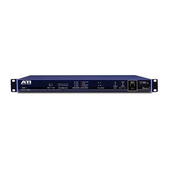
- Page 1 DDA & DSA SERIES AES/EBU DIGITAL AUDIO DISTRIBUTION AMPLIFIERS OPERATING AND MAINTENANCE MANUAL ...
- Page 2 The DSA Series operates much the same as the DDA Series; however, the DSA Series does not include the full featured display front panel and does not provide re-clocking of the digital input signal. The non-reclocking feature is essential when distributing Dolby E encoded AES signals and other clocked signals that should not be re-clocked.
- Page 3 RECEIVERS (Note that DSA Series units do not re-clock and provide no front panel status information. The following section applies to DDA Series units only.) The equalized AES/EBU data stream is applied to the receiver circuit U8 (U17) that is a Crystal Semiconductor CS8414 96kHz Digital Audio Receiver IC.
- Page 4 (Note that DSA Series units do not re-clock and provide no front panel status information. The following section applies to DDA Series units only.) The two most significant digits of the sample rate are decoded by U1 AND U4 and displayed if the sample rate is within +/- 4% of a standard rate.
- Page 5 OUTPUT DRIVERS DDAxxx-XLR and DSAxxx-XLR units use the balanced, 110-ohm, transformer coupled outputs and XLR type connectors shown on the referenced schematics. DDAxxx-BNC and DSAxxx-BNC units use the alternative 75-ohm unbalanced outputs to BNC coax connectors shown on the same schematics. The XLR outputs are in full compliance with specification AES3-1992 and the BNC outputs are in accordance with the recommendations of AES-3id-1995.
- Page 6 POWER If it is necessary to convert a unit wired for 115VAC to 230VAC operation, unplug the unit from the power source, remove the four cover mounting screws and locate the E1 jumpers next to the power transformer. Clip the jumpers 1-2 and 3- 4 (don’t unsolder), jumper from 2-3 carefully soldering together the free ends of 2-3 previously clipped.
- Page 7 SPECIFICATIONS INPUTS Connectors: XLR female or BNC, DC isolated from chassis. Input connector pairs paralleled for loop-thru. Level: 200mVp-p minimum Impedance: Transformer isolated, capacitor coupled, balanced and floating, XLR inputs 110 ohms, and BNC and RCA inputs 75 ohms. Terminating resistors may be switched in or out on rear panel.
- Page 8 INDICATORS (DDA only) Sample Rate: Numeric readout of first two digits of 32, 44.1, 48, 88.2, 96kHz rates if within +/-4%. Out of range blanks display Received Signal: Status: NO ERROR, LOCK, VALIDITY, and all Green for normal operation ...
Need help?
Do you have a question about the DDA SERIES and is the answer not in the manual?
Questions and answers