
Subscribe to Our Youtube Channel
Related Manuals for Lambda UF1500 Series


Summary of Contents for Lambda UF1500 Series
-
Page 1: Power Supply
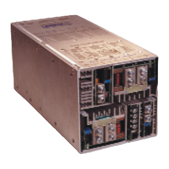
INSTALLATION MANUAL ULTRAFLEX POWER SUPPLY UF1500 Series 3055 Del Sol Blvd. San Diego, CA 92154 Phone: (619) 575-4400 Fax: (619) 429-1011 P/N: IMUE1500 Rev. C DATE: February 2002... -
Page 2: Table Of Contents
TABLE OF CONTENTS INTRODUCTION CERTIFICATION WARRANTY APPLICABILITY INSTALLATION MANUAL SAFETY AGENCY APPROVALS GENERAL SAFETY INSTRUCTIONS INPUT FUSE RECEIPT AND UNPACKING MOUNTING REQUIREMENTS AND COOLING INPUT POWER CONNECTIONS AC INPUT AND OUTPUT POWER RATINGS INPUT TRANSIENT/ESD PROTECTION REMOTE SENSE OUTPUT VOLTAGE ADJUSTMENT (TRIMMING) CURRENT LIMIT PROTECTION OVERVOLTAGE PROTECTION (OVP) OUTPUT LOAD REGULATION... - Page 3 TURN-OFF/TURN-ON TURN ON TIME NOISE AND RIPPLE DYNAMIC LOAD TRANSIENT RESPONSE DYNAMIC CROSS REGULATION TEMPERATURE COEFFICIENT NO LOAD OPERATION OVER TEMPERATURE SHUTDOWN OPERATING ENVIRONMENT SIZE AND WEIGHT COOLING SHOCK & VIBRATION PACKAGE DROP RELIABILITY PREDICTION MATING SIGNAL & CONTROL CONNECTOR INFORMATION GLOBAL SIGNALS OUTPUT MODULE SIGNALS &...
-
Page 4: Introduction
This power supply is warranted against defects in material and workmanship for a period of three years from date of shipment. During this period Lambda will either repair or replace this product at the discretion of Lambda . No other warranty is implied or given. -
Page 5: General Safety Instructions
SAFETY SYMBOL: This symbol indicates dangerous voltages present within the power supply. Isolation transformers should be used between the AC mains and the power supply if work is to be carried out with the safety covers removed. GENERAL SAFETY INSTRUCTIONS The UltraFlex power supply series is designed for use within other equipment or enclosures. -
Page 6: Input Fuse
A protective earth must be provided for safety in accordance with EN60950. WARNING: It is essential that the earth grounding terminal of this product be securely connected to earth (hard-wired) by the end user. PREVENTION OF ACCESS BY THE USER: This apparatus is intended to be accessible to authorized personnel only. -
Page 7: Mounting Requirements And Cooling
part number. All electrical tests performed on the unit prior to installation must be carried out by a qualified person familiar with AC/DC powered equipment and having the specialized knowledge required of the hazards associated with switched mode power supplies. This is particularly essential if the unit covers are removed, which exposes many devices operating at line voltage and some operating at peak voltages of up to 400 volts. -
Page 8: Emi
EMI pattern. The customer may require additional EMI filtering to meet system requirements. If problems are encountered, the customer should contact Lambda’s Application Engineering Staff. INPUT TRANSIENT/ESD PROTECTION The UltraFlex is designed to withstand surges, line transients, and ESD as specified in the... -
Page 9: Output Voltage Adjustment (Trimming)
OUTPUT VOLTAGE ADJUSTMENT (TRIMMING) Voltage adjust potentiometers are provided for all outputs. The potentiometers are located adjacent to the output connections of the power supply. Use a non-conductive trim-pot adjustment tool. Turn clockwise to increase the voltage. NOTE: Always monitor the corresponding output voltage while turning the potentiometer. CURRENT LIMIT PROTECTION All outputs are protected by constant-current limiting circuitry. -
Page 10: Dynamic Load Transient Response
Dual output modules: <1% pk-pk. DYNAMIC LOAD TRANSIENT RESPONSE A 25% step load change will result in an output deviation (overshoot or undershoot) of less than 3% of nominal output voltage (150mV for <5V outputs, 400mV for the </= 5V 1000W module). -
Page 11: Cooling
Reliability prediction MTBF by stress method per Bellcore TR-NWT-000332 Issue 4 (reliability prediction procedure for electronic equipment). Typical Quad output supply =/> 72000 hours MTBF (e.g. 5V/12V/12V/5V). MATING SIGNAL & CONTROL CONNECTOR INFORMATION Lambda Kit Part # (J3) Input Connector Kit 951482 (J1) Output Connector Kit... -
Page 12: Output Module Signals & Features
J1 pin 4 of each module together. A single remote sense point must be used. The individual output voltages must be set to within 1% of each other to ensure the outputs are within a 2% capture window. Refer to Lambda application note AN-018 for additional details. High Module Signal (J1 pin 5):... - Page 13 Inhibit Module (J1 pin 6 - single output module, J2 pin 1 - dual output module): A TTL "low" level signal can be applied to disable outputs to <0.5V at no load. Output Good Signal (J1 pin 7): This signal goes low if output deviates by - 4% from factory settings. Module Inverter O.K.
-
Page 14: Module Rating With Model Numbers: Ue Z 1 - X X X X X X
MODULE RATING WITH MODEL NUMBERS: UE Z 1 - X X X X X X Module Code TABLE 3 Module Output Current Output Power Slot Code Voltage DC (range) Width @ 50°C Max 2 V(1.8-2.2) 2 V(1.8-2.2) 132W 2 V(1.8-2.2) 100A 200W 3.3 V(3.0-3.6) -
Page 15: Note: Energy Hazards
Therefore, consideration should be given to electrical energy hazards from these outputs THERMAL DERATING GUIDELINE for UltraFlex UF1500 Power Supply Series Derating UF1500 Series Temperature [C] MAXIMUM POWER VS. AC LINE for UltraFlex UF1500 Power Supply Continuous Output Power Derating... - Page 16 OUTLINE DRAWING REV C Page 16 of 17...
-
Page 17: Label / Connection Diagram
LABEL / CONNECTION DIAGRAM REV C Page 17 of 17...
Need help?
Do you have a question about the UF1500 Series and is the answer not in the manual?
Questions and answers