Table of Contents
Advertisement
Quick Links
5" and 7" In-Wall
Touch Screens
Installation Guide
Introduction
The Control4® 5" or 7" In-Wall Touch Screen offers complete system control
in an elegant and compact design. These Touch Screens are equipped with a
capacitive Touch Screen surface and four (4) programmable shortcut buttons. The
power options are AC power or Power-Over-Ethernet (PoE). The device may be
connected via WiFi or Ethernet. Available for new construction or retrofits.
Supported Models
• C4-TSWMC5 – 5" In-Wall Touch Screen
• C4-TSWMC7 – 7" In-Wall Touch Screen
Associated SKUs:
• C4-TSWMC5-EG-WH – 5" In-Wall Touch Screen, White
• C4-TSWMC5-EG-BL – 5" In-Wall Touch Screen, Black
• C4-TSWMC7-EG-WH – 7" In-Wall Touch Screen, White
• C4-TSWMC7-EG-BL – 7" In-Wall Touch Screen, Black
Box Contents
Carefully unpack the contents of the box, and make sure the following items
are included in the box. If any item is missing or damaged, please contact your
Control4 Reseller.
• 5" or 7" In-Wall Touch Screen
• Power box (used to power the Touch Screen)
• Two (2) Orange wire nuts and two (2) screws to attach the power box.
• 5" and 7" In-Wall Touch Screens Installation Guide (this document)
Wallbox Kit Options
There are four (4) wall box options available to install this Touch Screen. Metal and
plastic wall boxes are available for new construction or retrofit installations.
•
5" or 7" In-Wall Touch Screen Wall Box Kits - New Construction
Plastic Model (C4-NWB57C-P)
Metal Model (C4-NWB57C-M)
•
5" or 7" In-Wall Touch Screen Wall Box Kit - Retrofit
Plastic Model (C4-RWB57C-P)
Metal Model (C4-RWB57C-M)
Refer to the Control4 5" or 7" In-Wall Touch Screen Wall Box Installation Guide
- New Construction or 5" or 7" In-Wall Touch Screen Wall Box Installation Guide -
Retrofit for your wall box installation instructions.
Accessories
• Control4 Power Over Ethernet Injector, sold separately (AC-POE1-B)
• 5" and 7" In-Wall Touch Screens Wall Box New Construction, Plastic
™
(C4-NWB57C-P)
• 5" and 7" In-Wall Touch Screens Wall Box New Construction, Metal (C4-
NWB57C-M)
• 5" and 7" In-Wall Touch Screens Wall Box Retrofit, Plastic (C4-RWB57C-P)
• 5" and 7" In-Wall Touch Screen Wall Box Retrofit, Metal (C4-RWB57C-M)
Requirements for In-Wall Installations
To install the 5" or 7" Touch Screen, you need the following:
• Home Controller HC-200B, HC-300C, or HC-1000 V3 fully installed and
configured with a Control4® system.
• Control4 5" and 7" Touch Screen custom wall box installed. See "Wall Box Kit
Options" in this document.
• If using Ethernet with PoE power:
- An Ethernet network installed and available that includes a gateway/router/
switch.
- Control4 PoE Injector (model #AC-POE1-B) or another third-party PoE
Injector or switch (which are certified to UL/ANSI standards).
- Two (2) Ethernet CAT5 cables to support your PoE Injector: (1) one that runs
from the Ethernet gateway/router/switch to the PoE Injector/switch and (2)
one that runs from the PoE Injector/switch to the Ethernet Touch Screen wall
box.
• If using Ethernet with AC power:
- An Ethernet network installed and available that includes a gateway/router/
switch.
- Access to in-wall AC power (a neutral connection is required).
- One (1) Ethernet CAT5 cable that runs from the Ethernet gateway/router/
switch to the Touch Screen.
• If using wireless with AC power:
- Wireless network (WiFi 802.11 b/g) installed and available with a wireless
access point (WAP).
- Access to in-wall AC power (a neutral connection is required).
- A 14-gauge electrical wire long enough to pull between the Touch Screen
and the power source.
Placement, Network Connection, and Power
Options
Place the Touch Screen in a convenient location at eye level, typically near the
entrance of the room, approximately 57 to 61 inches from the floor (see Figure 1).
Figure 1. Touch Screen Placement
New Device
AC Power (unless using PoE)
This device uses an Ethernet or WiFi network connection, and can be powered
using PoE or AC power. Note: Do not attempt to use PoE and AC at the same time.
Option 1: Ethernet Connection with a PoE Injector or a
Third-Party Injector or Switch
PoE injects electrical current into the Ethernet cable using a PoE Injector (model
#AC-POE1-B) or a third-party PoE solution to provide the Touch Screen with power
and a network connection. The 5" and 7" Touch Screens work with the Control4
PoE Injector or a third-party PoE Injector. To set up your PoE and Ethernet
connection with a PoE Injector, see Figure 2.
Figure 2. Ethernet Model - Requires Ethernet Connection to PoE Injector
Place the PoE Injector near your gateway/router/switch. Pull the Ethernet cable
from that location to where you want to install the Touch Screen.
Option 2: Ethernet Connection with AC
No PoE Injector is needed for Ethernet with AC power; the Ethernet is connected
directly to the switch. This power connection requires both neutral and hot
connections (see Figure 3).
Figure 3. Ethernet - Requires Connection to Ethernet and AC Power
Option 3: WiFi Connection with AC
WiFi placement: Place the Touch Screen above a power source, for example, an
outlet. Ensure that you have WiFi in the home (see Figure 4).
Figure 4. WiFi - Requires AC Power and WAP
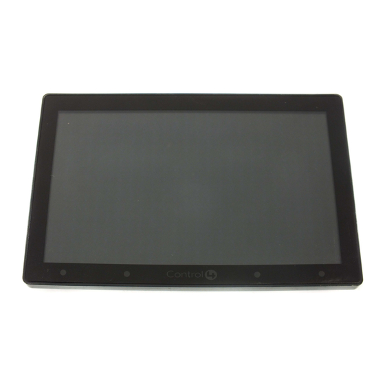
Front and Rear Panel Description
Front View
Figure 5. Front View - 5" or 7" In-Wall Touch Screen
1
2
1
Display: 5" or 7" viewing area, Touch Screen with 800 x 480 resolution.
2
Shortcut buttons (4): For custom programming; to initiate an action or
sequence of actions. Use Composer Pro or Composer HE to configure these
buttons.
3
Touch Screen Removal: Small hole located under the Touch Screen to remove
the Touch Screen from the wall.
- Front dimensions. 5" Touch Screen (H x W x D): 3.15" x 4.8 x 0.9" (80mm
x 122mm x 23mm); 7" Touch Screen (H x W x D): 4.6" x 6.9 x 0.9" (117mm x
175mm) x 23mm)
- Wall box dimensions. 5" or 7" Touch Screens (H x W x D): 2.7" x 4.1" x 2.4"
(68mm x 104mm x 61mm)
- Power box dimensions. 5" or 7" Touch Screens (H x W x D): 2.8" x 4.5" x 1.8"
(71mm x 114mm x 46mm)
Back View
Figure 6. Back View - 5" or 7" In-Wall Touch Screen and Power Box
1
1
Wireless Connection: Hot (H) uses Black wire; Return (R) uses White wire.
2
RJ-45 port for Ethernet Connection: Ethernet port available for either a
standard Ethernet source that provides network communication only OR a
PoE source that provides power to the device and network communication.
Installation
WARNING! For the location where you are installing the Touch Screen,
switch off the circuit breaker or remove the fuse from the fuse box.
AVERTISSEMENT! Pour l'endroit où vous installez l'écran tactile, coupez le
disjoncteur ou enlevez le fusible de la boîte de fusible.
WARNUNG! Für die Position, in der Sie die Berührungseingabe anbringen,
den Circuit breaker ausschalten oder die Sicherung vom Sicherung Kasten
entfernen.
3
2
Advertisement
Table of Contents

Related Manuals for Control 4 C4-TSWMC7


Summary of Contents for Control 4 C4-TSWMC7
- Page 1 Supported Models Display: 5” or 7” viewing area, Touch Screen with 800 x 480 resolution. one that runs from the PoE Injector/switch to the Ethernet Touch Screen wall No PoE Injector is needed for Ethernet with AC power; the Ethernet is connected box. Shortcut buttons (4): For custom programming; to initiate an action or directly to the switch. This power connection requires both neutral and hot • If using Ethernet with AC power: sequence of actions. Use Composer Pro or Composer HE to configure these • C4-TSWMC5 – 5” In-Wall Touch Screen connections (see Figure 3). buttons. - An Ethernet network installed and available that includes a gateway/router/ • C4-TSWMC7 – 7” In-Wall Touch Screen switch. Touch Screen Removal: Small hole located under the Touch Screen to remove Figure 3. Ethernet - Requires Connection to Ethernet and AC Power - Access to in-wall AC power (a neutral connection is required). the Touch Screen from the wall. Associated SKUs: - One (1) Ethernet CAT5 cable that runs from the Ethernet gateway/router/ - Front dimensions. 5” Touch Screen (H x W x D): 3.15” x 4.8 x 0.9” (80mm switch to the Touch Screen. x 122mm x 23mm); 7” Touch Screen (H x W x D): 4.6” x 6.9 x 0.9” (117mm x • C4-TSWMC5-EG-WH – 5” In-Wall Touch Screen, White • If using wireless with AC power: 175mm) x 23mm) • C4-TSWMC5-EG-BL – 5” In-Wall Touch Screen, Black - Wireless network (WiFi 802.11 b/g) installed and available with a wireless...
- Page 2 ™ • After initialization, press and hold the large red 4 on the center of the Touch IMPORTANT! Improper use or installation can cause LOSS/DAMAGE OF IMPORTANT! When cutting the opening for the wall box, DO NOT cut the • Align and carefully slide the power box into the wall box. Screen to enter the configuration screen. PROPERTY. opening too large. Be conservative and cautiously enlarge it as needed. Power Over Ethernet (PoE) Connection. Install a PoE Injector (sold • Press the Network button on the Touch Screen configuration page. The separately) or switch, and then connect the PoE Injector to the power and network configuration screen displays. IMPORTANT! L’utilisation ou l’installation inexacte peut causer LOSS/ IMPORTANT! En coupant l’ouverture pour la boîte de mur, ne coupez • Under Wireless, select Enable. If you don’t see the network you want, select DAMAGE DE PROPRIÉTÉ. pas l’ouverture trop grande. Soyez conservateur et agrandissez-avec network. Connect to the power box. The steps below describe how to install Other. précaution la comme nécessaire. Control4 PoE Injector. • At Network Name, select to add the SSID or wireless network when the WICHTIG! Unsachgemäßer Gebrauch oder Installation können LOSS/ keyboard appears. Select Done. • Connect the Control4 PoE Injector to a power source, for example, an AC DAMAGE DER EIGENSCHAFT verursachen. WICHTIG! Wenn Sie die öffnung für den Wandkasten schneiden, • At Security, select None, WEP 64, WEP 128, or WPA. At Password, type the outlet, using the power cord (provided with the unit).
- Page 3 ™ Warranty AVERTISSEMENT! Aimants! Dans l’emballage en plastique de ce produit sont inclus des aimants très puissants utilisés pour attacher les plaques de surface aux boites électriques. Si quelqu’un, manipulant ou utilisant ce produit est muni d’un pacemaker, défibrillateur ou autre dispositif d’ordre For complete warranty information, including details on consumer legal rights as médical, il doit éviter de se trouver à proximité (moins de 20 pouces) de well as warranty exclusions, visit www.control4.com/warranty. ce produit avant d’avoir consulté son médecin. Les champs magnétiques des aimants peuvent endommager le stockage d’information d’ordre About this Document magnétique (ex : cartes de crédit, bandes vidéo, disques durs d’ordinateur, etc.) Gardez tous les aimants au moins à 20 pouces de distance de tout type de stockage d’information d’ordre magnétique. Certains dispositifs Part Number: 200-00164 Rev I 7/12/2011 électroniques sont sensibles aux champs magnétiques et peuvent être endommagés de façon permanente ou être désactivés si ils sont exposés à un champs magnétique trop puissant. Pour plus d’information, consultez le manuel d’utilisateur propre à votre pièce électronique. SI avalés, les aimants peuvent causer des blessures graves et aussi causer la mort. Si des aimants ont été avalés (ou vous doutez qu’ils ont pu l’être) obtenez les soins médicaux de personnes compétentes immédiatement. Third-Party Trademarks Libertas Libertas Firmware copyright statement for Touch Screens 6/26/09 Copyright (c) 2006, One Laptop per Child and Marvell Corporation. All rights reserved. Redistribution. Redistribution and use in binary form, without modification, are permitted provided that the following conditions are met: * Redistributions must reproduce the above copyright notice and the following disclaimer in the documentation and/or other materials provided with the distribution. * Neither the name of Marvell Corporation nor the names of its suppliers may be used to endorse or promote products derived from this software without specific prior written permission. * No reverse engineering, decompilation, or disassembly of this software is permitted. * You may not use or attempt to use this software in conjunction with any product that is offered by a third party as a replacement, substitute or alternative to a Marvell Product where a Marvell Product is defined as a proprietary wireless LAN embedded client solution of Marvell or a Marvell Affiliate.
Need help?
Do you have a question about the C4-TSWMC7 and is the answer not in the manual?
Questions and answers