
Related Manuals for Elation Design Par 575D


Summary of Contents for Elation Design Par 575D
- Page 1 Design Par 575D Elation Professional 4295 Charter Street Los Angeles, Ca 90058 www.elationlighting.com Rev. 3/09/2007...
-
Page 2: Table Of Contents
Design Par 575D™ Contents General Information……………………………………………………………………… 3 a. Introduction………………………………………………………………………. 3 b. Unpacking………………………………………………………..…………..… 3 c. Customer Support…………………………………………….………………… 3 d. Warranty Registration……………………………………………………..…… 4 e. Discharge Lamp Warning……………………………………………………… 4 Safety Instructions………………………………………………………..…………. 6 Features…………………………………………………………………………………… 8 General Guidelines………………………………………………………………………. 9 Fixture Overview ………………………………………………………………………. 10 Lamp Installation…………………………………………………………………………. 13 a. -
Page 3: General Information
INTRODUCTION: Congratulations, you have just purchased one of the most innovative and reliable lighting fixtures on the market today! The Design Par 575D,™ has been designed to perform reliably for years when the guidelines in this booklet are followed. Please read and understand the instructions in this manual carefully and thoroughly before attempting to operate this unit. -
Page 4: Warranty Registration
Please do not discard the shipping carton in the trash. Please recycle whenever possible. WARRANTY REGISTRATION: The Design Par 575D™ carries a two year (730 days) limited warranty. Please fill out the enclosed warranty card to validate your purchase. All returned service items whether under warranty or not, must be freight pre-paid and accompany a return authorization (R.A.) number. - Page 5 Design Par 575D™ high-pressure environment to emit a brilliant output. Due to the high pressure involved with the construction of the lamp, the lamp may explode during prolonged extensive use. This risk is increased with age; added care is encouraged when dealing with older lamps. Thus, lamp should always be replaced at the end of their recommended duty cycle.
-
Page 6: Safety Instructions
2. Never touch the fixture during normal operation. This can cause severe personal injuries and/or damage to the fixture. 3. Be sure to unplug the DESIGN PAR 575D™ from the power outlet before performing any service related issues. 4. Lamp Replacement; Allow at least 30 minutes after disconnecting main power before you open the DESIGN PAR 575D™. - Page 7 Design Par 575D™ may increase the risk of damage and/or personal injury. 10. To reduce the risk of fire or shock, do not expose this fixture to rain or moisture. 11. Do not attempt to operate this fixture if the power cord has become damaged or frayed.
-
Page 8: Features
Design Par 575D™ 3. FEATURES • Pan 630° or 540˚ (User selectable) / Tilt 265° • 3 operation mode: DMX controlled, stand alone or sound activated • User Selectable Power Supply (Internal) • Control board with 4-digit display and foil-keyboard •... -
Page 9: General Guidelines
Design Par 575D™ 4. GENERAL GUIDELINES This fixture is a professional lighting effect designed for use on stage, in nightclubs, in theatres, etc. Do not attempt operation or installation without a proper knowledge on how to This fixture was designed for indoor use only. -
Page 10: Fixture Overview
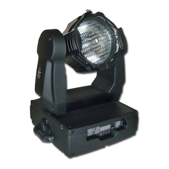
Design Par 575D™ 5. FIXTURE OVERVIEW 1) HEAD ASSEMBLY – This assembly holds the lamp, gel holder, lens, and reflector. 2) LAMP SOCKET ASSEMBLY COVER – This cover retains the lamp socket ©Elation Professional® Design Par 575D™... - Page 11 Never defeat this fuse. In the event of fuse failure, always be sure to replace with an exact match fuse unless other wise specified by an authorized Elation Professional technician. ©Elation Professional®...
- Page 12 Design Par 575D™ 13) DMX OUT JACK – This 3-pin XLR jack sends a DMX signal to another DMX fixture. For best results this jack should be terminated if it is the last fixture in a DMX daisy chain (see DMX termination on page 21).
-
Page 13: Lamp Installation
Design Par 575D™ . LAMP INSTALLATION INSTRUCTIONS Installing or replacing the lamp Only install the lamp with the device unplugged from the mains. The lamp has to be replaced when it is damaged or deformed. Before replacing the lamp be sure the unit has ample time to cool, to avoid injury to yourself never touch the lamp when it is hot. -
Page 14: Lamp Optimization
The minimum deviation amount is 1.0mm. Running the fixture within a lower deviation can cause damage to the lamp and/or lens. The Design Par 575D™ lamp holder is aligned at the factory. However, due to slight imperfections in all lamps, fine adjustments will improve light performance. Please follow the procedure below for proper lamp optimization: 1. - Page 15 Design Par 575D™ at a time until the light is evenly distributed. 4. If the light is brighter around the edge than it is in the center, or if light output is low, the lamp is too far back in the reflector. "Push” the lamp out by turning each of the adjustment screws ("1, 2, 3”) counterclockwise turn until the light is bright and evenly...
-
Page 16: Mounting And Installation
0,5m Mounting The DESIGN PAR 575D™ is fully operational in two different mounting positions, hanging upside-down from a ceiling, or set on a flat level surface (see illustration below). Be sure this fixture is kept at least 0.5m away from any flammable materials (decoration etc.). Always use and install the supplied safety cable as a safety measure to prevent accidental damage and/or injury in the event the clamp fails. -
Page 17: Mounting Positions
Design Par 575D™ Mounting points Overhead mounting requires extensive experience, including amongst others calculating working load limits, a fine knowledge of the installation material being used, and periodic safety inspection of all installation material and the fixture. If you lack these qualifications, do not attempt the installation yourself. - Page 18 Clamp Mounting The Design Par 575D™ provides a unique mounting bracket assembly that integrates the hanging yoke as well as the safety cable rigging point in one unit (see the illustration below). When mounting this fixture to truss be sure to secure an appropriately rated clamp to the hanging yoke using a M10 screw fitted through the center hole of the hanging yoke.
-
Page 19: Securing
Design Par 575D™ Securing the DESIGN PAR 575D™ Regardless of the rigging option you choose for your DESIGN PAR 575D™ always be sure to secure your fixture with a safety cable. The fixture provides a built-in rigging point for a safety cable on the hanging bracket as illustrated above. -
Page 20: Understanding Dmx
Design Par 575D™ 8. UNDERSTANDING DMX Data Cable (DMX Cable) Requirements (For DMX and Master/Slave Operation): Your fixture and your DMX controller require a standard 3-pin XLR connector for data input and data output (see figure below). If you are constructing your own cables be sure to use two conductor shielded digital cable rated at a 120 ohms (this cable can be purchased at almost all professional sound and lighting stores). -
Page 21: Dmx Terminator
Design Par 575D™ DMX-512 control connection Connect the provided XLR cable to the female 3-pin XLR output of your controller and the other side to the male 3-pin XLR input of the moving head (Please refer to the diagram below.). You can chain multiple moving heads together through serial linking. The cable needed should be two conductor, shielded cable with XLR input and output connectors that is specially designed for DMX data transmission. -
Page 22: 3-Pin To 5-Pin Conversion
In the case of the Design Par 575D™, which is a 6 channel fixture, you should set the starting DMX address of the first unit to 1, the second unit to 7 (6 + 1), the third unit to 13 (6 + 7), and so on. - Page 23 Design Par 575D™ "A.XXX" (XXX representing the actual DMX address). If the fixture is not receiving a DMX signal the display will flash "A.XXX" (XXX representing the actual DMX address). If your fixture is connected to a DMX controller and the display is flashing (not receiving a...
-
Page 24: Display Indicators
Design Par 575D™ 9. DISPLAY LED INDICATORS. The Design Par 575D™ has two LED indicators on the display. These indicators are designed to give a quick visual indication of the fixtures’ status. The illustration below details the functionality of the LED indicators. -
Page 25: Fixture Menu
LED Control Panel: The control panel located on the top, front of the fixture allows you to access the main menu and make all necessary adjustments to the Design Par 575D™. During normal operation, tapping the “MODE/ESC” key once will access the fixture’s main menu. - Page 26 Design Par 575D™ Manually switches lamp “on” and LAMP ON/OFF “off” Reset all motors and returns fixture to home RESE SCAN Reset only motors for pan/tilt Displays the total fixture running LIFE 0000~9999 time TIME LAMP 0000~9999 Displays a lamps running time...
-
Page 27: Menu Functions
DMX signal the display will flash continuously. To set or adjust a DMX address, please follow the procedure below: 1. Switch on the DESIGN PAR 575D™ and wait for the fixture reset process to finished. 2. Press the Mode/Esc button to access the main menu. Toggle through the menu by pressing the Up and Down buttons until the display shows A001. - Page 28 Design Par 575D™ will test the color channel, changing the color one by one and show the rainbow effect with different speeds. Again please remember, there are 8 DMX channels, and all can be tested 4. Press MODE/ENTER or EXIT to exit.
- Page 29 Design Par 575D™ confirm. 5. Press MODE/ESC to return to the main menu. LAMP MENU - – This menu function will manually turn the lamp on and off. Follow the procedure below to enter the lamp menu: 1. Access the main menu.
- Page 30 Design Par 575D™ 1. Access the main menu. 2. Tap the UP button until “RESE” is displayed, press ENTER. 3. Tap the UP button until “SCAN” is displayed, then press ENTER to confirm. 4. The display will show “ON/OFF”. Press the UP button to select “ON” to reset the color motor.
- Page 31 Design Par 575D™ 2. Tap the UP button until “TIME” is displayed, press ENTER. 3. Tap the UP button until “CLMP” is displayed, press ENTER. 4. Press MODE/ ENTER, the display will show “ON/OFF”. 5. Press the UP button to select “ON” to activate this function, or “OFF” to deactivate this function.
- Page 32 Design Par 575D™ will use 6 DMX channels. To access the Fine menu follow the procedure below: 1. Access the main menu. 2. Tap the UP button until “FINE” is displayed, press ENTER. 3. The display will show “ON/OFF”. 4. Press the UP button to select “ON” to activate this function, or “OFF” to deactivate this function.
- Page 33 Design Par 575D™ VALU – This function will display the DMX value of each channel as it is adjusted through the use of a DMX console. 1. Access the main menu. 2. Tap the UP button until “DISP” is displayed.
- Page 34 Design Par 575D™ RDMX - Allows DMX address to be changed via and external DMX controller. DLOF - Switch lamp off via DMX controller. DLAY - Lamp-on delay time. SPOT - This provides a spot beam for better lamp optimization.
- Page 35 Design Par 575D™ 4. The display will show “ON/OFF.” 5. Press the UP button to display “ON” to activate this function, or “OFF” to deactivate this function. 6. Press ENTER to confirm. 7. Press MODE/ESC to return to the main menu.
- Page 36 Design Par 575D™ – This function allows the user to set a lamp “strike” delay time. 1. Access the main menu. 2. Tap the UP button until “SPEC” is displayed, press ENTER. 3. Tap the UP button until “DLAY” is displayed, press ENTER.
- Page 37 Design Par 575D™ 5. Press the UP button to display “ON” to activate this function, or “OFF” to deactivate this function. 6. Press ENTER to confirm. 7. Press MODE/ESC to return to the main menu. FEED - Use this function to activate the pan/tilt error correction.
- Page 38 5. Once the proper password is entered the display will read “CHXX”, were as “XX” represents the fixture channel number, in the case of the Design Par 575D™ 1 ~ 6. Select the desired channel to be calibrated by pressing the UP or DOWN buttons and then ENTER to confirm.
- Page 39 Design Par 575D™ STXX (SC01 – SC48) - These are the scenes that are stored in your program. There are a total of 48 scenes. C-01 - C-11 (Channel 1 - Channel 11) – Represents the total fixture channels for each scene that can be edited.
- Page 40 Design Par 575D™ 5. Press ENTER to save and MODE/ESC to exit. SC01 - This function allows you to choose the total number of scenes in your internal program. 1. Access the main menu. 2. Tap the UP button until “EDIT” is displayed, press ENTER.
- Page 41 Design Par 575D™ 9. Once all the channels are completed, the display will begin to flash “TIME,” this indicates the time needed to run this scene. 10. Press ENTER to edit the time needed, the display shows TXXX , represents the time needed to run this scene. For example,...
- Page 42 Design Par 575D™ - This function allows you to “RUN” the user-installed program. You can set the number of steps under Step (S-01- S-48). You can edit the individual scenes under Edit. 1. Access the main menu. 2. Tap the UP button until “EDIT” is displayed, press ENTER.
-
Page 43: Dmx Channel Traits
Design Par 575D™ 11. DMX CHANNEL TRAITS: The chart below details the channel layout for 6 DMX channels (default). In 8bit mode the “Pan Fine” and “Tilt Fine” channels are not used, thus converting the fixture into a 4-channel DMX fixture. -
Page 44: Dmx Channel Values
Design Par 575D™ DMX channel function and values: DMX channel functions and their values (6 DMX channels): Channel 1 - Pan movement 8bit: Channel 2 – Pan fine Channel 3 - Tilt movement 8bit: Channel 4 – Tilt fine Channel 5 - Speed pan/tilt movement... -
Page 45: Error Codes
Design Par 575D™ 12. ERROR CODES: When power is applied, the unit will automatically enter a “reset/test” mode. This mode brings all the internal motors to a home position. If there is an internal problem with one or more of the motors an error code will flash in the display in the form of “XXer” were as XX will represent a function number. - Page 46 Design Par 575D™ (sensor failed or magnet is missing) or there is a stepper motor failure (defective motor or a defective motor IC drive on the main PCB). ©Elation Professional® Design Par 575D™...
-
Page 47: Cleaning And Maintenance
Design Par 575D™ 13. CLEANING AND MAINTENANCE The following points have to be considered during the inspection: 1. Be sure all screws and fasteners are securely tightened at all times. Lose screws may fall out during normal operation resulting in damage or injury as larger parts could fall. -
Page 48: Warranty
United States of America, including possessions and territories. It is the owner’s responsibility to establish the date and place of purchase by acceptable evidence, at the time service is sought. B. For warranty service, send the product only to the Elation Professional factory. All ®... - Page 49 The consumer’s and or Dealer’s sole remedy shall be such repair or replacement as is expressly provided above; and under no circumstances shall Elation Professional® be liable for any loss or damage, direct or consequential, arising out of the use of, or inability to use, this product.
-
Page 50: Photometric Data
Design Par 575D™ PHOTOMETRIC DATA: ©Elation Professional® Design Par 575D™... -
Page 51: Dimensional Drawings
Design Par 575D™ DIMENSIONAL DRAWINGS: ©Elation Professional® Design Par 575D™... -
Page 52: Circuit Schematic
Design Par 575D™ 17. Circuit Schematic ©Elation Professional® Design Par 575D™... -
Page 53: Technical Specifications
Design Par 575D™ 18. TECHNICAL SPECIFICATIONS Power supply Power consumption _98VAC, 50Hz; 120VAC, 50Hz; 208VAC, 50Hz; 220VAC, 50Hz; 230VAC, 50Hz; 240VAC, 50Hz; or 98VAC,60Hz; 120VAC,60Hz; 208VAC,60Hz; 220VAC,60Hz; 230VAC,60Hz; 240VAC,60Hz; Fuse protection 120V = 8A/250V, GMA (5x20mm fine-wire fuse) 220V = 4A/250V, GMA (5x20mm fine-wire fuse) - Page 54 Design Par 575D™ ©Elation Professional® Design Par 575D™...
- Page 55 Design Par 575D™ ©Elation Professional® Design Par 575D™...
- Page 56 Design Par 575D™ Elation Professional 4295 Charter Street Los Angeles, CA. 90058 323-582-3322 / 323-582-3108 fax www.ElationLighting.com / Info@ElationLighting.com ©Elation Professional® Design Par 575D™...
Need help?
Do you have a question about the Design Par 575D and is the answer not in the manual?
Questions and answers