Table of Contents
Advertisement
Chapter 1. Getting Started
Thank you for choosing the MS-7091 v1.X Micro ATX
mainboard. The MS-7091 v1.X mainboard is based on Intel
and Intel
ICH6R chipset for optimal system efficiency. Designed to
®
fit the advanced Intel
MS-7091 v1.X mainboard delivers a high performance and profes-
sional desktop platform solution.
Getting Started
Pentium Prescott LGA775 processor, the
®
Getting Started
915P
®
1-1
Advertisement
Table of Contents

Related Manuals for Medion MS-7091


Summary of Contents for Medion MS-7091
-
Page 1: Chapter 1. Getting Started
Getting Started Chapter 1. Getting Started Getting Started Thank you for choosing the MS-7091 v1.X Micro ATX mainboard. The MS-7091 v1.X mainboard is based on Intel 915P ® and Intel ICH6R chipset for optimal system efficiency. Designed to ® fit the advanced Intel Pentium Prescott LGA775 processor, the ®... -
Page 2: Mainboard Specifications
MS-7091 M-ATX Mainboard Mainboard Specifications Supports Intel Pentium 4 Prescott LGA775 processors in LGA775 package. ® Supports up to Pentium 4 3XX, 5XX sequence processor or higher speed. Supports Intel Hyper-Threading Technology. Chipset Intel 915P chipset ® - Supports FSB 533/800MHz. - Page 3 Getting Started - 1 Coaxial SPDIF-Out / SPDIF-In, 1 Optical SPDIF-Out / SPDIF-In - 1 MIC-In - 4 Line-Out - 1 Line-In ® VT6105L LAN Controller - 10/100 IEEE 802.3/802.3u 10Base-T & 100Base-T compliant. IEEE 1394 VT6307 PCI 1394a Integrated Host Controller ®...
-
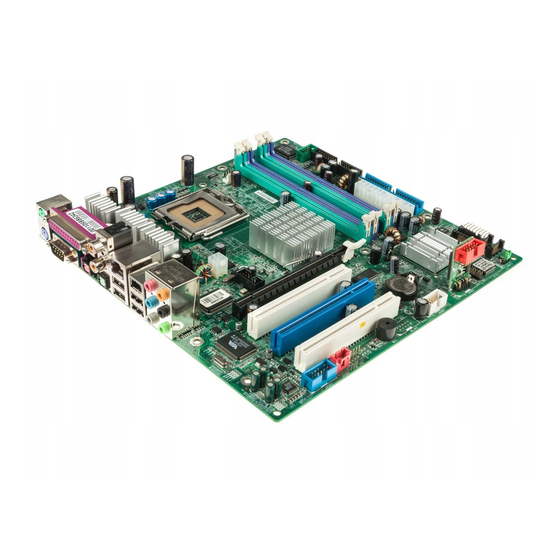
Page 4: Mainboard Layout
Coaxial SPDIF -In B: Optical SPDIF-Out T: LAN jack B: USB ports JPW1 Intel 915P T:IEEE 1394 B:USB ports VT6307 JSCA1 PCIE_X16 PCI 1 PCI 2 ICH6R PCI 3 SATA1 JUSB1 JUSB2 SATA2 JAUD1 JVID1 JL_IN1 JBAT1 MS-7091 v1.X M-ATX Mainboard... -
Page 5: Hardware Setup
Hardware Setup Chapter 2. Hardware Setup Hardware Setup This chapter tells you how to install the CPU, memory modules, and expansion cards, as well as how to setup the jumpers on the mainboard. Also, it provides the instructions on connecting the peripheral devices, such as the mouse, keyboard, etc. -
Page 6: Quick Components Guide
MS-7091 M-ATX Mainboard Quick Components Guide DDR DIMMs, p.2-7 JPW1, p.2-9 CANFAN1, p.2-14 CPU, p.2-3 JSMC1, p.2-15 Back Panel I/O, p.2-10 FDD1, p.2-14 ATX1, p.2-9 JSCA1, p.2-18 J1, p.2-17 IDE1, p.2-15 PCI-E slot, p.2-21 PCI slots, JF_P1, p.2-19 p.2-21 SATA1~SATA4, p.2-16... -
Page 7: Central Processing Unit (Cpu)
Hardware Setup Central Processing Unit: CPU The mainboard supports Intel Pentium 4 Prescott processor. The mainboard ® uses a CPU socket called LGA775. When you are installing the CPU, make sure to install the cooler to prevent overheating. If you do not have the CPU cooler, contact your dealer to purchase and install them before turning on the computer. -
Page 8: Cpu & Cooler Installation
MS-7091 M-ATX Mainboard CPU & Cooler Installation When you are installing the CPU, make sure the CPU has a cooler at- tached on the top to prevent overheating. If you do not have the cooler, contact your dealer to purchase and install them before turning on the computer. Meanwhile, do not forget to apply some silicon heat transfer compound on CPU before installing the heat sink/cooler fan for better heat dispersion. - Page 9 Hardware Setup 5. Lift the load lever up and open the 6. After confirming the CPU direction load plate. for correct mating, put down the CPU in the socket housing frame. Be sure to grasp on the edge of the CPU base. Note that the align- ment keys are matched.
- Page 10 MS-7091 M-ATX Mainboard 9. Press down the load lever lightly 10. Align the holes on the mainboard onto the load plate, and then se- with the heatsink. Push down the cure the lever with the hook under cooler until its four clips get retention tab.
-
Page 11: Memory
Hardware Setup Memory The mainboard provides 4 slots for 184-pin DDR SDRAM DIMM (Double In- Line Memory Module) modules and supports the memory size up to 4GB. You can install DDR400/DDR333 modules on the DDR DIMM slots (DIMM 1~4). DDR DIMM Slots (DIMM 1~4) Introduction to DDR SDRAM DDR (Double Data Rate) SDRAM is similar to conventional SDRAM, but dou-... -
Page 12: Installing Ddr Modules
MS-7091 M-ATX Mainboard Please refer to the following table for detailed dual-channel DDR. Other com- bination not listed below will function as single-channel DDR. DIMM1 (Ch A) DIMM2 (Ch A) DIMM3 (Ch B) DIMM4 (Ch B) System Density 128MB~1GB 128MB~1GB... -
Page 13: Power Supply
Hardware Setup Power Supply The mainboard supports ATX power supply for the power system. Before inserting the power supply connector, always make sure that all components are installed properly to ensure that no damage will be caused. ATX 24-Pin Power Connector: ATX1 This connector allows you to connect an ATX 24-pin power supply. -
Page 14: Back Panel
MS-7091 M-ATX Mainboard Back Panel The back panel provides the following connectors: MIC-in Line-In Coaxial-SPDIF Out BS-Out Coaxial-SPDIF In Parallel Port IEEE1394 Mouse Port Keyboard COM Port Optical Optical USB Ports C/S Out SPDIF-In SPDIF-Out SS-Out Line-Out Mouse/Keyboard Connector The mainboard provides a standard PS/2 mouse/keyboard mini DIN connector ®... -
Page 15: Serial Port Connector: Com Port
Hardware Setup RJ-45 LAN Jack The mainboard provides a RJ-45 connector that allows your computer to be connected to a network environment. Signal Description Transmit differential pair Transmit differential pair Receive differential pair Not used Not used LAN Jack Receive differential pair Not used (RJ-45) Not used... -
Page 16: Usb Connectors
MS-7091 M-ATX Mainboard USB Connectors The mainboard provides a UHCI (Universal Host Controller Interface) Universal Serial Bus root for attaching USB devices such as keyboard, mouse or other USB- compatible devices. You can plug the USB device directly into the connector. -
Page 17: Parallel Port Connector: Lpt1
Hardware Setup Parallel Port Connector: LPT1 The mainboard provides a 25-pin female centronic connector as LPT. A parallel port is a standard printer port that supports Enhanced Parallel Port (EPP) and Ex- tended Capabilities Parallel Port (ECP) mode. Pin Definition SIGNAL DESCRIPTION STROBE... -
Page 18: Connectors
MS-7091 M-ATX Mainboard Connectors The mainboard provides connectors to connect to FDD, IDE HDD, case, LAN, USB Ports, IR module and CPU/System/Power Supply FAN. Floppy Disk Drive Connector: FDD1 The mainboard provides a standard floppy disk drive connector that supports 360K, 720K, 1.2M, 1.44M and 2.88M floppy disk types. -
Page 19: Hard Disk Connector: Ide1
Hardware Setup Smart Card Reader Connector: JSMC1 The mainboard provides one smart card reader header for users to connect to smart card interface. Pin Definition Signal Signal VCC5 SCRST# JSMC1 SCPWR# SCPSNT SCIO SCLED SCCLK Hard Disk Connector: IDE1 The mainboard has one 32-bit Enhanced PCI IDE and Ultra DMA 33/66/100 controller that provides PIO mode 0~4, Bus Master, and Ultra DMA33/66/100 function. -
Page 20: Sata Connectors Controlled By Intel Ich6
MS-7091 M-ATX Mainboard Serial ATA Connectors controlled by Intel ICH6: SATA1~SATA4 The SouthBridge of this mainboard is Intel ICH6 which supports four serial ATA connectors SATA1~SATA4. SATA1~SATA4 are dual high-speed Serial ATA interface ports. Each supports generation serial ATA data rates of 150 MB/s. Both connectors are fully compliant with Serial ATA 1.0 specifications. -
Page 21: Front Panel Audio Connector: Jaud1
Hardware Setup IEEE 1394 Connectors: J1 The mainboard provides one IEEE1 pin header that allows you to connect IEEE 1394 port via front panel. Pin Definition SIGNAL SIGNAL TPA+ TPA- Ground Ground TPB+ TPB- Cable power Cable power Key (no pin) Ground Front Panel Audio Connector: JAUD1 The JAUD1 front panel audio connector allows you to connect front panel... -
Page 22: Front Usb Connector: Jusb1
MS-7091 M-ATX Mainboard Front Panel Connector: JF_P1 The mainboard provides one front panel connector for electrical connection to the front panel switches and LEDs. PS-ON PWR_LED JF_P1 HDD_LED Reset Front USB Connector: JUSB1 The mainboard provides one USB 2.0 pin header JUSB1 that is compliant with Intel I/O Connectivity Design Guide. - Page 23 Hardware Setup USB Wireless LAN Connector: JUSB2 This connector is specially designed to connect to the USB wireless device. JUSB2 Pin Definition SIGNAL SIGNAL +5V Dual +5V Dual USB1- JUSB2 USB1+ +3.3V Dual +3.3V Dual Video-In Connector: JVID1 The connector is for TV-Turner card audio connector. L GND R JVID1 Front Audio Line-In Connector: JL_IN1...
- Page 24 MS-7091 M-ATX Mainboard Jumpers The motherboard provides the following jumpers for you to set the computer’s function. This section will explain how to change your motherboard’s function through the use of jumpers. Clear CMOS Jumper: JBAT1 There is a CMOS RAM on board that has a power supply from external battery to keep the data of system configuration.
-
Page 25: Pci Express Slots
Hardware Setup Slots The motherboard provides one PCI Express x16 slot and three 32-bit PCI bus slots. PCI Express Slots The PCI Express slot, as a high-bandwidth, low pin count, serial, intercon- nect technology, support Intel highest performance desktop platforms utilizing the Intel Pentium 4 processor with HT Technology.
Need help?
Do you have a question about the MS-7091 and is the answer not in the manual?
Questions and answers