Table of Contents
Advertisement
Advertisement
Table of Contents

Subscribe to Our Youtube Channel
Related Manuals for Medion ms-7501M1


Summary of Contents for Medion ms-7501M1
- Page 1 MS-7501M1 (V2.X) Mainboard...
-
Page 2: Copyright Notice
Copyright Notice The material in this document is the intellectual property of the company. W e take every care in the preparation of this document, but no guarantee is given as to the correctness of its contents. Our products are under continual improvement and we reserve the right to make changes without notice. -
Page 3: Safety Instructions
Safety Instructions Always read the safety instructions carefully. Keep this User’s Manual for future reference. Keep this equipment away from humidity. Lay this equipment on a reliable flat surface before setting it up. The openings on the enclosure are for air convection hence protects the equip ment from overheating. -
Page 4: Fcc-B Radio Frequency Interference Statement
Shielded interface cables and A.C. power cord, if any, must be used in order to comply with the emission limits. VOIR LA NOTICE D’INSTALLATION AVANT DE RACCORDER AU RESEAU. MS-7501M1 This device complies with Part 15 of the FCC Rules. Operation is subject to the following two conditions:... -
Page 5: Table Of Contents
CONTENTS Copyright Notice ......................ii Tra dema rks ........................ii Revision History ......................ii Technical Support ....................... ii Safety Instructions ....................iii FCC-B Radio Frequency Interference Statement ..........iv Chapter 1 Getting Started ..................1-1 Mainboard Specifications ................... 1-2 Chapter 2 Hardware Setup ................... 2-1 Mainboard Layout .................... -
Page 7: Chapter 1 Getting Started
Getting Started Chapter 1 Getting Started Thank you for choosing the MS-7501M1 (V2.X) Micro- ATX mainboard. The MS-7501M1 (V2.X) is based on ® RS780 & SB700 chipsets for optimal system ® efficiency. Designed to fit the advanced AMD Phenom/ Athlon 64/ Sempron processors in Socket AM2/ AM2+, the MS-7501M1 (V2.X) delivers a high performance... -
Page 8: Mainboard Specifications
M S-7501M1 Mainboard Mainboard Specifications Proce ssor ® - Supports 95W AMD Phenom/ Athlon 64/ Sempron processors - Supports 4-pin CPU fan pinheader with Fan Speed Control - Hyper Transport supports up to 2.6GHz Chipset ® - North Bridge: AMD RS780 ®... - Page 9 Getting Started Floppy - 1 floppy port - Supports 1 FDD with 360KB, 720KB, 1.2MB, 1.44MB and 2.88MB Connectors Back Panel - 1 PS/2 mouse port - 1 PS/2 keyboard port - 1 LAN jack - 4 USB ports - 5 audio jacks - 1 optical S/PDIF-out jack - 1 IEEE 1394 port (Optional) On-Board Pinheader/ Connector...
-
Page 11: Chapter 2 Hardware Setup
Hardware Setup Chapter 2 Hardware Setup This chapter provides you with the information about hardware setup procedures. W hile doing the installation, be careful in holding the components and follow the installation procedures. For some components, if you install in the wrong orientation, the components will not work properly. -
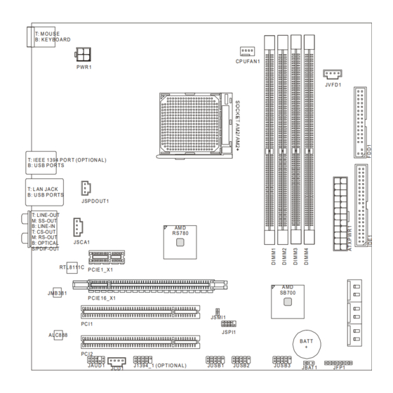
Page 12: Mainboard Layout
JA U D 1 J1 3 9 4 _ 1 ( OP T IO N A L ) JU S B 1 JU SB 2 JU S B 3 JB AT 1 JF P1 JCD 1 MS-7501M1 (V2.X) Micro-ATX Mainboard... -
Page 13: Cpu (Central Processing Unit)
Hardware Setup CPU (Central Processing Unit) ® The mainboard supports 95W AMD Phenom/ Athlon 64/ Sempron processors in Socket AM2/ AM2+. The Socket AM2/ AM2+ offers easy CPU installation. W hen you are installing the CPU, make sure the CPU has a heat sink and a cooling fan attached on the top to prevent overheating. - Page 14 M S-7501M1 Mainboard CPU Installation Procedures for Socket AM2/ AM2+ 1. Please turn off the power and unplug the power cord before installing the CPU. Open the lever Sliding the plate 90 degree 2. Pull the lever sideways away from the socket.
- Page 15 Hardware Setup Installing CPU Cooler Set When you are installing the CPU, make sure the CPU has a heat sink and a cooling fan attached on the top to prevent overheating. If you do not have the heat sink and cooling fan, contact your dealer to purchase and install them before turning on the computer.
-
Page 16: Memory
M S-7501M1 Mainboard Memory These DIMM slots are intended for memory modules. DDR2 240 pins, 1.8V 56x2=112 pins 64x2=128 pins Dual-Channel Memory Population Rules In Dual-Channel mode, the memory modules can transmit and receive data with two data bus lines simultaneously. Enabling Dual-Channel mode can enhance the system performance. -
Page 17: Installing Memory Modules
Hardware Setup Installing Memory Modules 1. The memory module has only one notch on the center and will only fit in the right orientation. 2. Insert the memory module vertically into the DIMM slot. Then push it in until the golden finger on the memory module is deeply inserted in the DIMM slot. -
Page 18: Power Supply
M S-7501M1 Mainboard Power Supply ATX 24-Pin Power Connector: ATXPWR1 pin 13 This connector allows you to connect an ATX 24-pin power supply. To connect the ATX 24-pin power supply, make sure the plug of the power supply is inserted in the proper orientation and the pins are aligned. -
Page 19: Back Panel
Hardware Setup Back Panel IEEE 1394 Line-Out CS-Out M ou se (Optional) SS-Out RS-Out Keyboard Line-In Optical S/PDIF-Out Mouse/ Keyboard ® ® The standard PS/2 mouse/keyboard DIN connector is for a PS/2 mouse/keyboard. IEEE 1394 Port The 1394 port on the back panel provides connection to 1394 devices. USB Port The USB (Universal Serial Bus) port is for attaching USB devices such as keyboard, mouse, or other USB-compatible devices. -
Page 20: Audio Ports
M S-7501M1 Mainboard Audio Ports These audio connectors are used for audio devices. You can differentiate the color of the audio jacks for different audio sound effects. Line-Out (Green) - Line Out, is a connector for speakers or headphones. SS-Out (Gray) - Side-Surround Out 7.1 channel mode. Line-In (Blue) - Line In, is used for external CD player, tape player or other audio devices. -
Page 21: Connector
Hardware Setup Connector Floppy Disk Drive Connector: FDD1 This connector supports 360KB, 720KB, 1.2MB, 1.44MB or 2.88MB floppy disk drive. FDD1 IDE Connector: IDE1 This connector supports IDE hard disk drives, optical disk drives and other IDE devices. IDE1 Important If you install two IDE devices on the same cable, you must configure the drives separately to master / slave mode by setting jumpers. - Page 22 M S-7501M1 Mainboard SPI Flash ROM Connector: JSPI1 This connector is used to flash SPI flash ROM. Pin Definition Description Description VCC3_SB VCC3_SB SPI_MISO_F SPI_MOSI_F JSPI1 SPI_CS0_F# SPI_CLK_F SPI_HOLD# Serial ATA Connector: SATA1~6 This connector is a high-speed Serial ATA interface port. Each connector can con- nect to one Serial ATA device.
- Page 23 Hardware Setup Fan Power Connector: CPUFAN1 The fan power connectors support system cooling fan with +12V. W hen connecting the wire to the connectors, always note that the red wire is the positive and should be connected to the +12V; the black wire is Ground and should be connected to GND. If the mainboard has a System Hardware Monitor chipset onboard, you must use a specially designed fan with speed sensor to take advantage of the CPU fan control.
- Page 24 M S-7501M1 Mainboard CD-In Connector: JCD1 This connector is provided for external audio input. JCD1 Front Panel Audio Connector: JAUD1 This connector allows you to connect the front panel audio and is compliant with ® Intel Front Panel I/O Connectivity Design Guide. JAUD1 HD Audio Pin Definition SIGNAL...
- Page 25 Hardware Setup S/PDIF-Out Connector: SPDOUT1 This connector is used to connect S/PDIF (Sony & Philips Digital Interconnect Format) interface for digital audio transmission. SPDIF SPDOUT1 Front USB Connector: JUSB1~3 ® This connector, compliant with Intel I/O Connectivity Design Guide, is ideal for con- necting high-speed USB interface peripherals such as USB HDD, digital cameras, MP3 players, printers, modems and the like.
- Page 26 M S-7501M1 Mainboard Front Panel Connectors: JFP1 The mainboard provides one front panel connector for electrical connection to the ® front panel switches and LEDs. JFP1 is compliant with Intel Front Panel I/O Connec- tivity Design Guide. JFP1 Pin Definition SIGNAL DESCRIPTION PS_ON...
- Page 27 This connector allows you to connect the output device with SCART spec. SCART is the established European standard for connecting home video equipments like TVs, VCRs, DVD players, etc. JSCA1 Front LCD Module Connector: JVFD1 This connector allows you to connect to Medion VFD LCD panel. JVFD1 2-17...
-
Page 28: Jumper
M S-7501M1 Mainboard Jumper Clear CMOS Jumper: JBAT1 There is a CMOS RAM onboard that has a power supply from an external battery to keep the data of system configuration. W ith the CMOS RAM, the system can auto- matically boot OS every time it is turned on. If you want to clear the system configuration, set the jumper to clear data. - Page 29 Hardware Setup Slot PCI (Peripheral Component Interconnect) Express Slot The PCI Express slot supports the PCI Express interface expansion card. The PCI Express x16 slot supports up to 4.0 GB/s transfer rate. The PCI Express x1 slot supports up to 250 MB/s transfer rate. PCI Express x16 Slot PCI Express x1 Slot PCI (Peripheral Component Interconnect) Slot...
Need help?
Do you have a question about the ms-7501M1 and is the answer not in the manual?
Questions and answers