Nera F77 Installatioin Manual
F77 nera
Hide thumbs
Also See for F77:
- User manual (90 pages) ,
- Installation manual (54 pages) ,
- Brief operating instructions (2 pages)
Table of Contents
Advertisement
Quick Links
Advertisement
Table of Contents

Related Manuals for Nera F77


Summary of Contents for Nera F77
- Page 1 Nera F77 Installation Manual Nera F77...
- Page 3 Access to the interior of the equipment shall be made by a Nera qualified technician only. The equipment shall be installed by a Nera SatCom approved Installation & Service Agent.
-
Page 5: Table Of Contents
MCU connectors ..................16 Lower connector panel ................16 Example of BDE installation ..............17 Example of Nera F77 installation cabling arrangement ......18 Placing the Main Communication Unit (MCU) ......... 19 Placing the Distress Alarm Unit & ISDN Handset ........19 Placing the ISDN Handset as a standard telephone ....... -
Page 6: System
40 W in receive/idle mode, and approx. 150 W in transmit mode. A CD supplied with the equipment contains a program for control and operation from PC. See the Nera F77 - User Manual. Nera ISDN Handset The Nera ISDN Handset keypad and built-in display allows dialing and control of the MCU and antenna. -
Page 7: Above Deck Equipment - Ade
SYSTEM Above Deck Equipment - ADE The Nera F77 Above Deck Equipment consists of: • Servo stabilized antenna dish with RF-Transceiver • Mast mounted radome, or • Deck mounted radome Mast mounted radome (cutaway view) BDE - ADE Coaxial Cable... -
Page 8: Planning
PLANNING Placing the Antenna Radome type Nera F77 is delivered either with mast mounted or deck mounted radome. See previous page. The mast mounted version includes a hatch which provides access for service and repair, whereas on the deck mounted version the radome top must be lifted off before servicing. - Page 9 Do not locate the antenna close to interfering signal sources, or in such a position that the source (e.g. radar-antenna) radiates directly into the Nera F77 antenna. The Above Deck Equipment (ADE) should be separated as far as possible from other transmitters, and preferably by at least...
-
Page 10: Designing The Antenna Mast
If the height of the mast exceeds approximately 4.5 metres, an access platform should be attached to the mast approximately 1 metre below the radome bottom. Be aware that requirements may vary from one country to another. Antenna Unit Mounted on Mast Nera F77 Continuing the Saturn tradition... -
Page 11: Outline Dimensions Of Antenna Radome (Mast Mounted Version)
PLANNING Outline dimensions of Antenna radome (mast mounted version) Optional steel Antenna Mast, R906569 Weight: 85 kg Weight: approx. 59 kg For welding onto deck Nera F77 Continuing the Saturn tradition... -
Page 12: Outline Dimensions Of Antenna Radome (Deck Mounted Version)
Installation Manual PLANNING Outline dimensions of Antenna radome (deck mounted version) Weight: approx. 45 kg Nera F77 Continuing the Saturn tradition... - Page 13 PLANNING Nera F77 Continuing the Saturn tradition...
-
Page 14: Physical Characteristics Of Main Units
Installation Manual PLANNING Physical characteristics of main units cont'd Nera F77 Continuing the Saturn tradition... -
Page 15: Mcu Connectors
PLANNING Nera F77 Continuing the Saturn tradition... -
Page 16: Mcu Connectors
Installation Manual PLANNING MCU connectors Lower connector panel Nera F77 Continuing the Saturn tradition... -
Page 17: Example Of Bde Installation
PLANNING Nera F77 Continuing the Saturn tradition... -
Page 18: Example Of Nera F77 Installation Cabling Arrangement
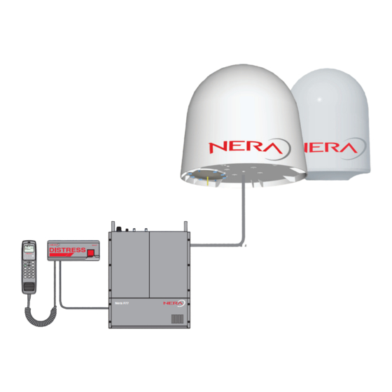
Installation Manual SYSTEM Example of Nera F77 installation cabling arrangement The installation includes four Nera ISDN Handsets (two w/Distress Alarm Unit), Group 3 and 4 telefaxes, PC w/printer, Data Equipment and two Analogue Telephones. Nera F77 Continuing the Saturn tradition... -
Page 19: Placing The Main Communication Unit (Mcu)
MCU mounting plate allows the unit to be secured to the wall or desk top. Placing the Distress Alarm Unit & Nera ISDN Handset The Distress Alarm Unit is operated in conjunction with a Nera ISDN Handset. The Nera ISDN Handset functions as a display and communication unit for alert transmission. -
Page 20: Placing The Telefax (Option)
232/RS-422 port can also be used for control and configuration of the Main Communication Unit. This requires that the vtLite Marine program accessible on the Nera F77 CD is installed. Connection to the USB/RS-232/RS-422 port also allows 64 kbps data transmission. -
Page 21: Grounding Considerations
Mains power/ground Mains ground must be checked against the common grounding point (MCU mounting plate). It is important to use the same mains branch for additional equipment connected to the MCU (fax, PC w/printer etc.). Nera F77 Continuing the Saturn tradition... - Page 22 Installation Manual PLANNING Grounding considerations cont'd Location of the MCU for best possible grounding. See also INSTALLATION: "Location and grounding of Units". Nera F77 Continuing the Saturn tradition...
-
Page 23: Laying Cables
The coaxial cable from the Antenna Unit should be given a Communication Unit free end of approximately 0.5 m at the MCU location. Nera ISDN Handset, Choose the position for the required wall sockets and lay Distress Alarm Unit, the cables leaving a free end of 0.5 m. Also allow a free end of telefax or analogue 0.5 m at the Termination Box. -
Page 24: Telephone Wiring
Installation Manual PLANNING Telephone wiring Nera F77 Continuing the Saturn tradition... -
Page 25: Installation
Secure the ADE to the mast flange using the enclosed toothed washers and nuts. Tighten the nuts applying a torque of 100 Nm. Finally, remove the lifting rope. grounding stud Nera F77 Continuing the Saturn tradition... -
Page 26: Deck Mounted Version
Secure the ADE using the enclosed toothed washers and nuts. Tighten the nuts applying a torque of 100 Nm. Finally, remove the rope. Keep the rope for hoisting the antenna down for service. grounding stud Nera F77 Continuing the Saturn tradition... -
Page 27: Ade - Connecting Coaxial Cable To Mast Mounted Antenna
(see Appendices 1 – 6). Connect the RF plug to the Antenna Unit coaxial connector as shown. The minimum bending radius of the coaxial cable is 10 times the cable diameter. Nera F77 Continuing the Saturn tradition... -
Page 28: Ade - Connecting Coaxial Cable To Deck Mounted Antenna
(see Appendices 1 – 6). Connect the RF plug to the Antenna Unit coaxial connector as shown. If required, use a coax angle adapter. The minimum bending radius of the coaxial cable is 10 times the cable diameter. Nera F77 Continuing the Saturn tradition... -
Page 29: Installing The Below Deck Equipment (Bde)
INSTALLATION Installing the Below Deck Equipment (BDE) Location and grounding of units Nera F77 Continuing the Saturn tradition... -
Page 30: Bde - Example Of Local Or Near-By Installation
Installation Manual INSTALLATION Nera F77 Continuing the Saturn tradition... -
Page 31: Bde - Example Of Remote Installation
INSTALLATION Nera F77 Continuing the Saturn tradition... -
Page 32: Connection Box Qufc 911 918 (Option)
Installation Manual INSTALLATION Connection Box QUFC 911 918 (option) Nera F77 Continuing the Saturn tradition... -
Page 33: Nera Isdn Handset
INSTALLATION Nera ISDN Handset The ISDN Handset is to be plugged into the ISDN socket located on the connector panel of the MCU, or to the Distress Alarm Unit (if installed). Note! It is not recommended to extend the handset cable by more than 6 m. -
Page 34: Mounting The Main Communication Unit (Mcu)
Installation Manual INSTALLATION Nera F77 Continuing the Saturn tradition... -
Page 35: Bde - Connecting The Coaxial Cable To The Mcu
MCU or "pigtail". Mount the N-plug on the cable in accordance with the instructions (see Appendices 1 - 6). For thicker coax cable, use the "pigtail" for connection of the Antenna cable to the MCU. Nera F77 Continuing the Saturn tradition... -
Page 36: Examples Of Below Deck Equipment
Installation Manual INSTALLATION Examples of Below Deck Equipment Nera F77 Continuing the Saturn tradition... -
Page 37: Isdn Telephones/Equipment
INSTALLATION ISDN telephones/equipment Nera F77 Continuing the Saturn tradition... -
Page 38: Isdn Wall Socket
Installation Manual INSTALLATION ISDN telephones/equipment cont'd ISDN wall socket Nera F77 Continuing the Saturn tradition... -
Page 39: Distress Alarm Unit
When longer than 10 metres, the end of the ISDN bus must be terminated by two resistors as shown below. Only one bus/termination per MCU. Be aware that only one ISDN cable is permitted to be longer than 10 metres. Nera F77 Continuing the Saturn tradition... -
Page 40: Analogue Telephones
1 cm of the insulation from each core and connect to centre terminals 4 and 5. Interchanging of the wires at terminals 4 and 5 has no effect. R 906676/1 Nera F77 Continuing the Saturn tradition... -
Page 41: Pc - Asynchronous Data Communication
125 Ring Indicator Signal from Nera F77. This signal is used in the Auto answer OFF mode and when ON indicates that an incoming call is in progress. The signal will go OFF when the call is answered by the PC by turning circuit 108 Data Terminal Ready ON. -
Page 42: Nmea-0183 Input Sources (Complies With Iec 61162-1)
If the primary source is not receiving GPS signals, the external GPS input will be used (if enabled). NMEA-0183 input is not required for operation of Nera F77. The NMEA-0183 (ver. 3.00) input is a 4 - 15 V current loop interface located on the connector panel of the MCU. -
Page 43: Appendix 1
Mounting connector type 11N-50-3-54 (for cable RG223/U) Tools and materials required: • Stanley blade • Scissors • Solder Sn/Pb 60/40 activated rosin flux • Spanner 7 mm (74 Z-0-0-38) 8 mm (74 Z-0-0-16) 13 mm (74 Z-0-0-37) Nera F77 Continuing the Saturn tradition... -
Page 44: Mounting Connector Type 11N-50-7-5 (For Cables Rg214/Ethernet 06230)
Insert connector body. Screw in and tighten nut A with wrenches of 16 mm, type 74Z 0-0-3, until rubber gasket C is split. Do not distort cable and connector body. Armoured cable: Finally, screw on and tighten armour clamp. Nera F77 Continuing the Saturn tradition... -
Page 45: Mounting Connector Type 11N-50-10-4 (For Cable S10172 B-11)
APPENDIX 3 Mounting connector type 11N-50-10-4 (for cable S10172 B-11) Tools and materials required: • Stanley blade • File • Spanners (18, 20, 22 mm) • Sand paper (300 or 400) • Scissors braid braid Nera F77 Continuing the Saturn tradition... -
Page 46: Mounting Connector Type 11N-50-12-10 (For Cable Rf 1/2" 50)
Installation Manual Nera F77 Continuing the Saturn tradition... -
Page 47: Mounting Connector Type 11N-50-23-10 (For Cable Rf 7/8" 50)
APPENDIX 5 Mounting connector type 11N-50-23-10 (for cable RF 7/8" 50) Nera F77 Continuing the Saturn tradition... -
Page 48: Mounting Connector Type 11N-50-32-2/11N-50-42-2 (For Cables Rf 1 1/4"/15/8" 50)
Installation Manual APPENDIX 6 Mounting connector type 11N-50-32-2/11N-50-42-2 (for cables RF 1 1/4"/15/8" 50) Nera F77 Continuing the Saturn tradition... -
Page 49: Appendix 7
Above Deck Unit, 101993 Deck mounted radome (cutaway view) Below Deck Equipment w/accessories, QUFC911964 Main Communication Unit (MCU) 100141 AC mains cable for F77 MCU 101818 Distress Alarm Unit 101154 Cable for DA, 4 x 0.22, 10 m TFKR41206/8 Nera ISDN Handset... -
Page 50: Appendix 7
100149 MUB board incl. base plate bracket 102195 ISDN / Analogue Terminal Adapter incl. base plate 102196 Strap for F77 FAR Radome Installation & Service (lifter) 102188 Small fuse 5x20 (5A slow) NGH24104/5 Screw M3.5 x 9.5 cylinder head, selftapping,... -
Page 51: Appendix 8
APPENDIX 8 Cable pinouts ISDN cable QRPM 911 111-3000 (3 m) -10000 (10 m) Analogue telephone cable QRPM 911033-2000 ( 2 m) USB cable 100001 (3 m) Nera F77 Continuing the Saturn tradition... - Page 52 RS-422 cable 9-pin to 25-pin printer cab Note! If using the standard 9 pin female-to-25 pin male printer cable QRPM911010/5000, apply a 9 pin male- to-9 pin male adapter for connection to the MCU. Nera F77 Continuing the Saturn tradition...
-
Page 53: Appendix 9
APPENDIX 9 Serial printer settings Nera F77 Continuing the Saturn tradition... - Page 54 The design of Nera F77 with L-band (1.5/1.6 GHz) signals between ADE and BDE, easily enable insertion of an Inmarsat Demodulator to pick up broadcast RF signals via the BROADBAND (DGPS) TNC connector.
-
Page 55: Appendix 11
APPENDIX 11 Activation of "Radio Silence" A “Radio Silence” function may be activated in the Nera F77 terminal. The function may be opened from the vtLite Marine program, via the Function menu > Advanced functions > Customize > Paid functions. See the User Manual. -
Page 56: Appendix 12
Installation Manual APPENDIX 12 Azimuth Angle Map Elevation Angle Map Nera F77 Continuing the Saturn tradition... -
Page 57: Appendix 13
APPENDIX 13 Previous type radome Weight: 72 kg Nera F77 Continuing the Saturn tradition... - Page 60 Nera ASA Nera SatCom AS Bergerveien 12, PO Box 91 N-1375 Billingstad, Norway Tel: +47 67 24 47 00 Fax: +47 67 24 46 21 www.nera.no...
Need help?
Do you have a question about the F77 and is the answer not in the manual?
Questions and answers