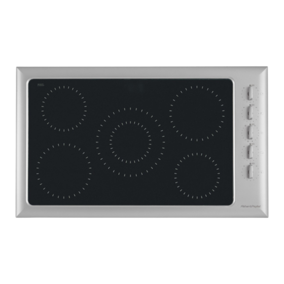
Fisher & Paykel CE901 Service Manual
Ceramic cooktop
Hide thumbs
Also See for CE901:
- User manual (48 pages) ,
- Installation instructions manual (25 pages) ,
- Installation information (45 pages)
Table of Contents
Advertisement
Advertisement
Table of Contents

Subscribe to Our Youtube Channel
Summary of Contents for Fisher & Paykel CE901
-
Page 1: Ceramic Cooktop
CERAMIC COOKTOP MODELS CE901 AND CE901M 599098... - Page 2 - 2 -...
-
Page 3: Models Covered By This Manual
599098 Issue A - April 2003 MODELS COVERED BY THIS MANUAL Fisher and Paykel CE901 Titan Ceramic Cooktop MODEL CODE MARKET CE901 88414 United States of America/Canada CE901M 88418 United States of America/Canada CE901M 87815 New Zealand CE901M 87825 Australia... -
Page 4: Table Of Contents
CONTENTS MODELS COVERED BY THIS MANUAL ................3 SERVICE ASSISTANCE .....................3 SERVICING & SAFETY PRECAUTIONS..............5 1.1 WARNINGS ......................5 SPECIFICATIONS......................6 2.1 DIMENSIONS ......................6 2.2 COUNTERTOP CUTOUT DIMENSIONS ..............6 2.3 ELECTRICAL SPECIFICATIONS ................7 2.4 LOCATION OF SERIAL NUMBER AND PRODUCT INFORMATION ......7 SERVICING INSTRUCTIONS ..................8 3.1 REMOVAL FROM THE COUNTERTOP..............8 3.2 REPLACING ELEMENTS ..................9 3.3 REPLACING ENERGY REGULATORS..............12... -
Page 5: Servicing & Safety Precautions
(L1 and L2 in the US) connected together to protect the electronics. The CE901 cooktop contains electronic components that can be damaged by electrostatic discharge from your fingers. A grounded wrist strap must be worn when handling electronic components or wiring connected to electronic components. -
Page 6: Specifications
SPECIFICATIONS 2.1 DIMENSIONS Market Width Depth Height HM Height HC inch inch inch inch 3 1/8 3 1/8 AU, NZ, GB, IE 2 3/4 3 1/4 2.2 COUNTERTOP CUTOUT DIMENSIONS - 6 -... -
Page 7: Electrical Specifications
Current Approvals Max. Amps 35.4 UL858 NZ, GB, IE IEC 60335 35.4 IEC 60335 ELEMENTS Position Size Power F&P Part Number inches CE901 CE901M Right Rear 1800 355747 355747 Left Rear 6 1/2 1200 355746 355746 Centre 2500 531148 531148... -
Page 8: Servicing Instructions
SERVICING INSTRUCTIONS 3.1 REMOVAL FROM THE COUNTERTOP Isolate the unit from the power supply by turning off the main switch and removing the fuse or fuses where more than one phase is used. Check that the circuit is dead by attempting to operate the appliance. -
Page 9: Replacing Elements
3.2 REPLACING ELEMENTS Isolate the cooktop from the power supply and remove it from the countertop as described in 3.1. Remove the three self tapping screws between the main cover and the 45° end panel. Remove the eight screws and plastic standoffs that hold the main cover. - Page 10 Slide the element springs between the cross-member and element case so they are positioned centrally over the screw holes in the element case and beneath the holes in the cross-member. Element Element Case Screw Hole Numbers Dual Element 6, 30, 42 and 66. 1800W Element 21 and 57.
- Page 11 Conduit Equipped Models (US). Earth Terminal Block models (AU, NZ, GB and IE). Once back in the counter top and reconnected to the supply, check the function of each element by switching to a medium setting and observing its operation. Look for the cycling of the energy regulator by observing the glow of the element as it heats and cools.
-
Page 12: Replacing Energy Regulators
Remove the two screws that retain the wiring duct (raceway) cover. Remove the cover. The cover part number and name is, 531180 Bracket cover wire clamp CE901. - 12 -... - Page 13 Remove the two screws that hold the duct (raceway) to the frame. Remove the wiring from the regulator that is to be replaced, taking note of the position of each wire. Remove the four fine thread screws that retain the regulator mounting panel.
- Page 14 Refit the wiring to the regulator(s). On US models, the wiring in the regulator box must be restrained so it cannot contact live terminals of other circuits. The wiring is to be bunched and taped to the wiring restraint rod with glass cloth insulation tape as shown in 3.5.
-
Page 15: Replacing Hot/On Lights
3.4 REPLACING HOT/ON LIGHTS Isolate the cooktop from the power supply and remove it from the countertop as described in 3.1. Remove the four screws that retain the regulator box cover and remove the cover. Models in Aust, NZ, GB and IE, will have wires attached to the inside of the cover through the terminal block. - Page 16 531162 Harness LED Short White CE901M Iridium Long 531163 Harness LED Long White CE901M Standard Short 531104 Harness LED Short CE901 Standard Long 531105 Harness LED Long CE901 Push the new harnesses LEDs into the light bezel with its head firmly against the end of its cavity.
- Page 17 On US models, the wiring in the regulator box must be restrained so it cannot contact live terminals of other circuits. The wiring is to be bunched and taped to the wiring restraint rod with glass cloth insulation tape as shown in 3.5. Refit the raceway cover.
-
Page 18: Internal Wire Restraint
3.5 INTERNAL WIRE RESTRAINT – Use 200°C rated glass cloth tape (F&P part 556339 TP 3M 69 GLASS CLOTH SI 19x33M). Apply tape wraps to the wire bundles at the six locations Apply tape wraps to the where they pass under the wire bundles approximately cross-members. - Page 19 US Models only. Gather wires away from the regulators and apply tape wraps at approximately half way between the regulators. Apply a further tape wrap at approximately half way between the Wires must not be free to contact live last regulator and the terminal block. terminals.
-
Page 20: Wiring Diagram - Standard Models
3.6 WIRING DIAGRAM – STANDARD MODELS - 20 -... -
Page 21: Wiring Diagram - Iridium Models
3.7 WIRING DIAGRAM – IRIDIUM MODELS - 21 -...


Need help?
Do you have a question about the CE901 and is the answer not in the manual?
Questions and answers