Advertisement
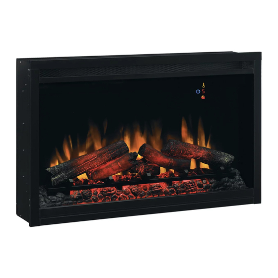
ELECTRIC BUILDERS BOX
Electric Builder Box
INSTALLATION GUIDE
36EB110-GRT, 36EB111-GRC
36EB220-GRT, 36EB221-GRC
CONSUMER SAFETY INFORMATION
PLEASE READ THIS MANUAL BEFORE USING THIS APPLIANCE
IF THE INFORMATION IN THIS MANUAL IS NOT FOLLOWED,
AN ELECTRIC SHOCK OR FIRE MAY RESULT CAUSING PROPERTY
DO NOT STORE OR USE GASOLINE OR OTHER FLAMMABLE
Thank you and congratulations on your purchase of a Classic Flame electric
builder box. Please read the installation instructions before installing and
operating this appliance.
IMPORTANT:
Failure to follow these instructions may result in a possible electric shock,
fire hazard and/ or injury and will void the warranty.
For Customer Service:
E-Mail: parts@twinstarhome.com
In English Call: 866-661-1218
In French Call: 866-374-9203
In Spanish Call: 866-661-1218
MODEL NUMBERS:
WARNING
DAMAGE, PERSONAL INJURY OR LOSS OF LIFE.
VAPORS AND LIQUIDS IN THE VICINITY OF THIS
OR ANY OTHER APPLIANCE.
Read all instructions and warnings carefully before using.
E-1
Twin-Star International, Inc.
Delray Beach, FL 33445
U.S.A.
Made in China
Printed in China
©2010,Twin-StarInternational,Inc.
Advertisement
Table of Contents

Related Manuals for ClassicFlame 36EB110-GRT


Summary of Contents for ClassicFlame 36EB110-GRT
-
Page 1: Installation Guide
ELECTRIC BUILDERS BOX Electric Builder Box INSTALLATION GUIDE MODEL NUMBERS: 36EB110-GRT, 36EB111-GRC 36EB220-GRT, 36EB221-GRC CONSUMER SAFETY INFORMATION PLEASE READ THIS MANUAL BEFORE USING THIS APPLIANCE WARNING IF THE INFORMATION IN THIS MANUAL IS NOT FOLLOWED, AN ELECTRIC SHOCK OR FIRE MAY RESULT CAUSING PROPERTY DAMAGE, PERSONAL INJURY OR LOSS OF LIFE. -
Page 2: Listings And Code Approvals
THE BUILDERS BOX SERIES HAS BEEN TESTED AND APPROVED IN ACCORDANCE WITH CSA AND UL STANDARDS FOR FIXED AND LOCATION DEDICATED ELECTRIC ROOM HEATERS. MODEL SPECIFICATIONS RATED POWER AMPS VOLTAGE MODEL NUMBER DESCRIPTION WATTS 1440 36EB110-GRT 36” TRADITIONAL 4400 36” TRADITIONAL 2100/2800 10.1/11.7 36EB220-GRT 208/240 6700/8900 36EB111-GRC 36”... -
Page 3: Section 1: Preparation
( see figure 1.) Figure 3 Figure 1 Sign Wire DOWN FLAME TIMRER Control Box with bracket HEAT SLEEP Remote Control FLAME EMBERS 36EB110-GRT 36EB220-GRT Sign Wire DOWN FLAME TIMRER DOWN LIGHT EFFECTS Control Box with bracket HEAT SLEEP FLAME Remote Control... - Page 4 Do not remove the protective plastic film at this time. Place the frame in a safe place( see figure 2.) Figure 3 Figure 2 36EB110-GRT 36EB220-GRT STEP 1 UNSCREW 2...
-
Page 5: Specifications
Framing Specification: Figure 3 Section 3: Recommended Power Supply Wire Specifications For 36EB110-GRT & 36EB111-GRC installations use three non-metallic sheathed cables with ground wire for the power supply. Use the appropriate wires to meet local and national electrical codes for rated power consumption. -
Page 6: Section 4: Mounting
2.) Remove the screws holding side panels and then remove the side panels (see figure 4 & 5). 3.) Insert the builders box into the opening in the framing. Figure 4: Mounting Tab Location 36EB111-GRC 36EB110-GRT 36EB221-GRC 36EB220-GRT Figure 5: Wall and Mounting Tabs... - Page 7 4.) Install the builders box using 4pcs screws from the inside of the builder box (see figure 6 & 7). 5.) Remount the side panels. 6.) Place the stones as desired.(Only for 36EB111-GRC & 36EB221-GRC ) 7.) Remount the front frame. Figure 6: Mounting Tab Location 36EB111-GRC 36EB110-GRT 36EB221-GRC 36EB220-GRT Figure 7: Wall and Mounting Tabs...
- Page 8 8.) Ensure that all connections are tight. 9.) Secure all the wiring with wire-caps, then insert into the junction box. 10.) Remount the junction box cover (see figure 8 & 9.) Note: 36EB110-GRT & 36EB111-GRC will only run on 120 volt operation. Figure 8 120 V...
- Page 9 SECTION 5: 208/240V WIRING INSTRUCTIONS 1.) Loosen the screw securing the junction box cover and remove the cover. 2.) Pull the power supply wires through the hole in the cover. 3.) Pull out the 5 wires marked L1, L2, N, G, S from the junction box on the side of the builder box.
- Page 10 SECTION 6: INSTALL CONTROL BOX 1. Mount the control box bracket to the wall using provided screws. 2. Connect control panel wire to extension cable. 3. Insert the control box to the bracket and finish the control box installation. Figure 10 E-10...
- Page 11 SECTION 6: CHECK & TEST 1.) Recheck that all the wiring works. Check that all connections are tight and correct to the manual. 2.) Switch on the power supply to the unit. 3.) Press the POWER button on the control box. 4.) Using the wall controls test all the functions to ensure they are working correctly.
-
Page 12: Section 10: Wiring Schematic
SECTION 10: WIRING SCHEMATIC E-12... - Page 13 E-13...
- Page 14 E-14...
- Page 15 E-15...
Need help?
Do you have a question about the 36EB110-GRT and is the answer not in the manual?
Questions and answers