Table of Contents
Advertisement
Advertisement
Table of Contents

Related Manuals for THOMSON SHDSL


Summary of Contents for THOMSON SHDSL
- Page 1 Thomson Gateway SHDSL Configuration Guide R8.2 and higher...
-
Page 3: Thomson Gateway
Thomson Gateway SHDSL Configuration Guide R8.2 and higher... - Page 4 Distribution and copying of this document, use and communication of its contents is not permitted without written authorization from Thomson. The content of this document is furnished for informational use only, may be subject to change without notice, and should not be construed as a commitment by Thomson. Thomson assumes no responsibility or liability for any errors or inaccuracies that may appear in this document.
-
Page 5: Table Of Contents
Portfolio Overview ..................13 Front Panel ....................14 Back Panel ....................15 LED Behaviour and Connector Layout ............16 4 Configuring and Operating the SHDSL Interface ....19 Simple Back-to-Back Setup ................20 SHDSL CLI 1-2-3 .................... 25 CLI Reference ....................27 5 Modem Options ................. - Page 6 Contents E-DOC-CTC-20080313-0001 v2.0...
-
Page 7: About This Shdsl Configuration Guide
Terminology Generally, a Thomson Gateway of the SHDSL product portfolio will be referred to as a Thomson SHDSL device in this SHDSL Configuration Guide. Typographical Conventions... - Page 8 About this SHDSL Configuration Guide E-DOC-CTC-20080313-0001 v2.0...
-
Page 9: Introduction
EFM over SHDSL: Ethernet frames mapped in SHDSL framing. In case the TC-layer is set to ATM, support of the optional SHDSL-bonding feature, referred to as (ATM) M-pair operation. Both the 2-wire/4-wire mode as well as the scalable M-pair mode are supported. - Page 10 DSL modem. link: this term refers to a DSL circuit in the SHDSL chip. Each DSL link is terminated on the back- panel connector and can be connected to a single DSL line. A device with one DSL link is also referred to as a single pair device.
-
Page 11: Shdsl Overview
Standard Compliancy Introduction Thomson’s SHDSL implementation attempts to be as compliant as possible with the relevant standards in force at the time of product release. The main reason for this goal is to achieve as much interoperability with as many as possible counterparts. - Page 12 5696 kbps ITU-T G.994.1 SHDSL is a complex link layer and to use it in a flexible way, some form of “auto-negotiation” is needed. For this function, SHDSL transceivers rely on ITU-T Recommendation G.994.1, often abbreviated as G.Hs. This recommendation specifies the mechanism and procedures that DSL transceivers must use to exchange their individual capabilities and to select a common mode of operation.
- Page 13 (E-OAM). Clause 61 specifies items common to the 10PASS-TS and 2BASE-TL EFM systems which apply to voice grade copper media. This clause also specifies the optional PAF function. Clause 63 is 2BASE-TL specific, which is the EFM system used in combination with SHDSL modulation. Following IEEE 802.3-2005 clauses are relevant to the Thomson SHDSL devices:...
-
Page 14: Transmission Convergence (Tc) Layers
The remainder of this section briefly explains each combination and enumerates the main advantages and disadvantages. ATM TC - Single pair In case the ATM TC-layer is enabled on a single SHDSL link, a stream of 53 byte ATM cells is converted into an octet stream which is fed into the SHDSL transceiver. Advantages: ATM is a well proven technology. - Page 15 EFM TC - Single pair In case the EFM TC-layer is enabled on a single SHDSL link, a stream of variable-sized Ethernet frames is first converted into 64 byte EFM fragments. Next, these fragments are 64/65-octet encoded and fed into the SHDSL transceiver.
-
Page 16: Capacity Characteristics
SHDSL Overview Capacity Characteristics Introduction This section gives an idea of the maximum link capacity of a Thomson SHDSL device in case the TC-layer is set to EFM. Two cases should be considered: EFM TC - Single pair EFM TC - M-pair G.SHDSL offers symmetrical data rates from 192 kbps up to 2312 kbps in 64 kbps increments. - Page 17 SHDSL Overview Maximum link capacity (fps) Ethernet frame size (bytes) PFS = 64 PFS = 128 PFS = 256 PFS = 512 1024 1 217 1 289 1 327 1 347 1518 PFS is short for PAF Fragment Size (octets). By default, the PFS is set to 256 octets.
- Page 18 SHDSL Overview E-DOC-CTC-20080313-0001 v2.0...
-
Page 19: Thomson Shdsl Devices
Portfolio Overview SHDSL product portfolio This document is applicable to following Thomson SHDSL devices: TG605s ST620s TG628s Product capabilities and limits Following table lists the capabilities and the upper limits for the different SHDSL devices: Capabilities TG605s TG605s ST620s TG628s (1-pair) -
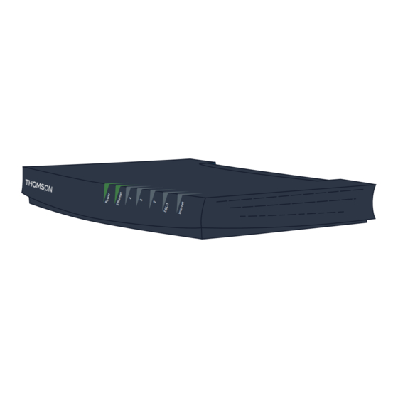
Page 20: Front Panel
The following illustration shows the front panel of a Thomson SHDSL device (TG628s): LEDs The Thomson SHDSL device is equipped with a number of LEDs on its front panel, indicating the state of the device during normal operation. The following table shows the meaning of the different LEDs of a TG628s, which supports four DSL links and... -
Page 21: Back Panel
22V DC Console DSL-0 DSL-1 Buttons and connectors The Thomson Gateway is equipped with the following buttons and connectors on its back panel. Listed from left to right: Power socket On/Off switch Serial interface Reset button (to reset the device to the manufacturing defaults) -
Page 22: Led Behaviour And Connector Layout
Thomson SHDSL Devices LED Behaviour and Connector Layout DSL LED behaviour The behaviour of the DSL LEDs indicates the different phases in the DSL start-up process: Step DSL link status LED state Silent Sending G.Hs tones Green - Blinking at 2 Hz G.Hs message exchange... - Page 23 Thomson SHDSL Devices TG605s (2-pair variant): Connector name Link ID [0..3] RJ14 Pin [1..6] Signal (Tip/Ring) on back panel DSL-0 Ring Ring ST620s: Connector name Link ID [0..3] RJ14 Pin [1..6] Signal (Tip/Ring) on back panel DSL-0 Ring Ring TG628s: Connector name Link ID [0..3]...
- Page 24 Thomson SHDSL Devices E-DOC-CTC-20080313-0001 v2.0...
-
Page 25: Configuring And Operating The Shdsl Interface
Configuring and Operating the SHDSL Interface Introduction The purpose of this chapter is to explain the configuration and operation of the Thomson SHDSL interface in detail, via the CLI commands located in the xdsl CLI sub-tree: The simple back-to-back setup illustrates the CPE and CO mode of SHDSL devices. -
Page 26: Simple Back-To-Back Setup
Simple Back-to-Back Setup Introduction This section describes a simple SHDSL back-to-back setup. A first SHDSL device is operated in CPE mode and is connected to a second one in CO mode. Both SHDSL devices are configured for transparent bridging. Back-to-back setup... - Page 27 {Administrator}=>:atm phonebook delete name=atm_pvc_0_35 Disable the broadcast filter on the bridge. This way, broadcasts (e.g. ARP requests) that arrive on a WAN interface are correctly received by the SHDSL device (and not dropped): {Administrator}=>:eth bridge config filter=none Make these changes permanent. This will be the starting point for our configuration: {Administrator}=>:saveall...
- Page 28 =>:env set var=Usr_Prompt value={TG628s-CPE} Configure the IP address as follows: {TG628s-CPE}=>:ip ipadd intf=lan1 addr=10.0.0.10 netmask=24 addroute=enabled Save the configuration: {TG628s-CPE}=>:saveall By default, a Thomson SHDSL device is configured in CPE mode. No extra configuration of SHDSL is required. E-DOC-CTC-20080313-0001 v2.0...
- Page 29 The DSL LEDs should behave like described in section “ DSL LED behaviour” on page 16 (off - 2 Hz - 4 Hz - solid green). Once the SHDSL links achieve showtime, information on the DSL interfaces can be displayed as follows: {TG628s-CPE}=>:xdsl iflist name=dsl0 DSL-interface: dsl0 --------------...
- Page 30 Tx Power Upstream (dBm) Tip/Ring Reversal Errored Seconds Severe Errored Seconds Loss Of Sync Word Seconds Unavailable Seconds {TG628s-CO}=> You should be able to ping from PC1 to PC2 successfully as soon as the SHDSL connection is established. E-DOC-CTC-20080313-0001 v2.0...
-
Page 31: Shdsl Cli 1-2-3
SHDSL CLI 1-2-3 Introduction In order to get a Thomson SHDSL device up and running with minimal configuration effort, the Thomson Gateway is provided with a default SHDSL configuration, configuring the device in CPE mode. The main characteristics of this default configuration are: The DSL interface uses the default CPE profile. - Page 32 Internal operation The Utopia data bus, which is an ATM bus, is used for communication between the SHDSL chip and the NWP. For correct internal operation in case of EMF TC, an ATM interface with destination PVC 0.32 is required. This interface is present by default and should not be removed from the configuration.
-
Page 33: Cli Reference
Configuring and Operating the SHDSL Interface CLI Reference Overview This section describes following SHDSL-related CLI commands: “:xdsl add” on page “:xdsl delete” on page “:xdsl ifadd” on page “:xdsl ifattach” on page “:xdsl ifconfig” on page “:xdsl ifdelete” on page “:xdsl ifdetach”... - Page 34 Configuring and Operating the SHDSL Interface :xdsl ifadd :xdsl ifadd To create a new DSL interface, execute the command Following two parameters must be specified: name: the name of the new DSL interface. profile: the name of a DSL profile that was created in advance.
- Page 35 Configuring and Operating the SHDSL Interface int-channel: this parameter indicates the internal communication channel used by the DSL interface. none: if this parameter is set to none, the DSL link(s) can still be initialized but not the ATM channel. This value is mainly intended for testing purposes only.
- Page 36 Configuring and Operating the SHDSL Interface To display summarized information (only the state sections) on DSL interfaces, execute the command :xdsl iflist If the TC-layer is set to ATM, following information is displayed: =>:xdsl iflist DSL-interface: dsl0 -------------- State: ------...
- Page 37 Configuring and Operating the SHDSL Interface :xdsl iflist To display extended information on a specific DSL interface, execute the command specify the name of a specific interface. If the profile type is CO, the default parameter values are displayed as follows: =>:xdsl iflist name=dsl0...
- Page 38 Configuring and Operating the SHDSL Interface :xdsl profile add :xdsl profile add To create a new DSL profile, execute the command Following two parameters must be specified: name: the name of the new DSL profile. type: the profile type. Two values are possible: For example, create a new profile as follows: =>:xdsl profile add name=test-profile type=cpe...
- Page 39 Configuring and Operating the SHDSL Interface For example, display information on the default DSL profiles as follows: =>:xdsl profile list name=def-cpe Profile: def-cpe ---------------- Profile Type : CPE PAF Fragment Size (octets) : 256 Physical Layer Options (Modem-Options) ATM Up Fast...
- Page 40 Configuring and Operating the SHDSL Interface force-tcpam16 force-tcpam32 lineprobing simulate-lp vendor-specific The profile type is CO: annex: this parameter indicates which regional requirements are taken into account: af: the regional requirements of ITU-T G.991.2 Annex A&F (North America) are used.
-
Page 41: Modem Options
Introduction The modem options, also referred to as the physical layer options, are part of a DSL profile of type CPE. These modem options are used during the SHDSL handshake procedure, when the CPE establishes a connection with the CO. -
Page 42: Modem-Option Reference
If disabled, the ATM TC layer is enabled when the DSL link status achieves data mode. If enabled, the ATM TC layer is already enabled at the beginning of the SHDSL training. This can be necessary if the DSLAM requires that the ATM TC layer is synchronized within a few seconds. - Page 43 Modem Options simulate-lp: If disabled, line probing is not simulated. If enabled, line probing is simulated. This option can be used if the DSLAM does not send probing tones when asked during training. The simulation starts with a low connect rate. Then, it measures the SNR in showtime and based on that changes the connect rate and re-synchronizes until it has an acceptable SNR.
- Page 44 Modem Options E-DOC-CTC-20080313-0001 v2.0...
-
Page 46: Prins Boudewijnlaan
THOMSON Telecom Belgium Prins Boudewijnlaan 47 2650 Edegem www.thomson-broadband.com © Thomson 2008. All rights reserved. E-DOC-CTC-20080313-0001 v2.0.
Need help?
Do you have a question about the SHDSL and is the answer not in the manual?
Questions and answers