
Related Manuals for Autronica Autro Safe


Summary of Contents for Autronica Autro Safe
- Page 1 Release 4 Installation Handbook AutroSafe Interactive Fire Detection System 116-P-ASAFE-INSTALL/DGB Rev. I, 2014-04-01, Autronica Fire And Security AS...
- Page 2 This product should not be mixed with other commercial wastes for disposal. Installation Handbook, AutroSafe Interactive Fire Detection System, 116-P-ASAFE-INSTALL/DGB Rev. I, 2014-04-01, Autronica Fire and Security...
-
Page 3: Table Of Contents
Overview – BS-420 / BC-420 ............32 BS-420 / BC-420 ................33 8.2.1 AL_Com+ Connection on Controller Board BSA-400 ..... 33 Installation Handbook, AutroSafe Interactive Fire Detection System, Release 4, 116-P-ASAFE-INSTALL/DGB Rev. I, 2014-04-01, Autronica Fire and Security AS Page 3... -
Page 4: Autronica Fire And Security As Page
11.3 Connections Overview ..............55 11.3.1 Connections – AutroKeeper BN-180 ........57 11.3.2 Switch Settings – AutroKeeper BN-180 ........57 Installation Handbook, AutroSafe Interactive Fire Detection System, Release 4, 116-P-ASAFE-INSTALL/DGB Rev. I, 2014-04-01, Autronica Fire and Security AS Page 4... -
Page 5: Autronica Fire And Security As Page
15.7 Button S2 – Start on S2 on Standby Source ........80 15.8 Configuration Settings ............... 81 15.9 Dipswitch table – S5 and S6 ............. 82 Installation Handbook, AutroSafe Interactive Fire Detection System, Release 4, 116-P-ASAFE-INSTALL/DGB Rev. I, 2014-04-01, Autronica Fire and Security AS Page 5... -
Page 6: Autronica Fire And Security As Page
15.13.2 Battery Input ................. 86 15.14 Part of an AutroFieldBus Network ............. 86 15.15 Power Unit BPS-405 / BPS-410 as Standalone ........ 86 Installation Handbook, AutroSafe Interactive Fire Detection System, Release 4, 116-P-ASAFE-INSTALL/DGB Rev. I, 2014-04-01, Autronica Fire and Security AS Page 6... -
Page 7: Introduction
1.2 The Reader The handbook is intended to be used by Autronica Fire and Security trained service and technical personnel who are responsible for the installation of the AutroSafe Interactive Fire Detection System, Release 4. -
Page 8: Reference Documentation
Datasheet; AutroKeeper BN-180 116-P-BN180/CGB bn180_cgb For detailed technical information on Phoenix Ethernet Switches, refer to Phoenix Contact web site at http://select.phoenixcontact.com/phoenix/dwl/dwlfr1.jsp?lang=en Installation Handbook, AutroSafe Interactive Fire Detection System, Release 4, 116-P-ASAFE-INSTALL/DGB Rev. I, 2014-04-01, Autronica Fire and Security AS Page 8... -
Page 9: Pre-Installation
175 cm above the floor. Other panels should be mounted accordingly. 175 cm Installation Handbook, AutroSafe Interactive Fire Detection System, Release 4, 116-P-ASAFE-INSTALL/DGB Rev. I, 2014-04-01, Autronica Fire and Security AS Page 9... -
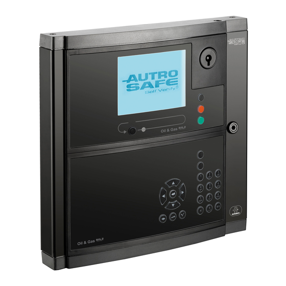
Page 10: System Units - Overview
The Information Panel serves as an indication device only. It provides information related to the defined operation zone(s). Dimensions: HxWxD (mm): 195 x 350 x 84 Installation Handbook, AutroSafe Interactive Fire Detection System, Release 4, 116-P-ASAFE-INSTALL/DGB Rev. I, 2014-04-01, Autronica Fire and Security AS Page 10... - Page 11 6 outputs 24VDC (max. 2A each) 1 fault relay output Dimensions: HxWxD (mm): 420 x 346 x 146 Installation Handbook, AutroSafe Interactive Fire Detection System, Release 4, 116-P-ASAFE-INSTALL/DGB Rev. I, 2014-04-01, Autronica Fire and Security AS Page 11...
- Page 12 6 outputs 24VDC (max. 2A each) 1 fault relay output Dimensions: HxWxD (mm): 130 x 259 x 120 Installation Handbook, AutroSafe Interactive Fire Detection System, Release 4, 116-P-ASAFE-INSTALL/DGB Rev. I, 2014-04-01, Autronica Fire and Security AS Page 12...
-
Page 13: Loop Panels - Overview
Fire Brigade Loop Panel (BU-110) Mounted onto a wall bracket (UD-732). Dimensions (mm): HxWxD (mm): 310 x 154 x 45 Installation Handbook, AutroSafe Interactive Fire Detection System, Release 4, 116-P-ASAFE-INSTALL/DGB Rev. I, 2014-04-01, Autronica Fire and Security AS Page 13... -
Page 14: Mounting Instructions
This product contains static-sensitive devices. Always use an antistatic wrist strap / earth bracelet to avoid any electrostatic discharge. Installation Handbook, AutroSafe Interactive Fire Detection System, Release 4, 116-P-ASAFE-INSTALL/DGB Rev. I, 2014-04-01, Autronica Fire and Security AS Page 14... -
Page 15: Mounting Fire Alarm Control Panel Bs-420 / Controller Bc-420
The 2 upper holes are of key- hole-type. Partly fasten the upper Installation Handbook, AutroSafe Interactive Fire Detection System, Release 4, 116-P-ASAFE-INSTALL/DGB Rev. I, 2014-04-01, Autronica Fire and Security AS Page 15... - Page 16 Insert the text foils (in For detailed description of the the appropriate various text foils, language) into their see chapter 5.8. respective positions. Installation Handbook, AutroSafe Interactive Fire Detection System, Release 4, 116-P-ASAFE-INSTALL/DGB Rev. I, 2014-04-01, Autronica Fire and Security AS Page 16...
-
Page 17: Mounting The Operator Panel Bs-430
9. Installation Handbook, AutroSafe Interactive Fire Detection System, Release 4, 116-P-ASAFE-INSTALL/DGB Rev. I, 2014-04-01, Autronica Fire and Security AS Page 17... -
Page 18: Mounting Repeater Panel Bu-Bv-420
The upper 3 holes are of key- hole-type. Partly fasten the upper screws. Hang the cabinet onto the upper screws. Installation Handbook, AutroSafe Interactive Fire Detection System, Release 4, 116-P-ASAFE-INSTALL/DGB Rev. I, 2014-04-01, Autronica Fire and Security AS Page 18... - Page 19 Insert the text foils (in description of the the appropriate various text foils, language) into the their see chapter 5.8. respective positions. Installation Handbook, AutroSafe Interactive Fire Detection System, Release 4, 116-P-ASAFE-INSTALL/DGB Rev. I, 2014-04-01, Autronica Fire and Security AS Page 19...
-
Page 20: Mounting Loop Panels (Bv-110 And Bu-110)
Installation Handbook, AutroSafe Interactive Fire Detection System, Release 4, 116-P-ASAFE-INSTALL/DGB Rev. I, 2014-04-01, Autronica Fire and Security AS Page 20... -
Page 21: Mounting Power Cabinet Bp-405
Hang the cabinet onto the upper screws. Partly fasten the bottom screw. Tighten all screws. Installation Handbook, AutroSafe Interactive Fire Detection System, Release 4, 116-P-ASAFE-INSTALL/DGB Rev. I, 2014-04-01, Autronica Fire and Security AS Page 21... - Page 22 Connect the red cable from the connector on the Power Board to the plus pole on the lowermost battery. Installation Handbook, AutroSafe Interactive Fire Detection System, Release 4, 116-P-ASAFE-INSTALL/DGB Rev. I, 2014-04-01, Autronica Fire and Security AS Page 22...
- Page 23 230VAC or 24VDC. Installation Handbook, AutroSafe Interactive Fire Detection System, Release 4, 116-P-ASAFE-INSTALL/DGB Rev. I, 2014-04-01, Autronica Fire and Security AS Page 23...
-
Page 24: Mounting Power Supply Unit Bps-405 / Bps-410
24V/10A power supply), a calibration procedure must be performed. Refer to the Commissioning Handbook, Calibration Procedure – Power Unit BPS-410. Installation Handbook, AutroSafe Interactive Fire Detection System, Release 4, 116-P-ASAFE-INSTALL/DGB Rev. I, 2014-04-01, Autronica Fire and Security AS Page 24... -
Page 25: Inserting Text Foils
(along the perforation holes). Fire Alarm Control Panel BS-420 is shown in the example below. Installation Handbook, AutroSafe Interactive Fire Detection System, Release 4, 116-P-ASAFE-INSTALL/DGB Rev. I, 2014-04-01, Autronica Fire and Security AS Page 25... -
Page 26: Cable Inlets / Outlets
ø23 x 6 The illustration above shows the positioning and dimensions of the cable inlets for BS-420/BC-420 (the uppermost illustration) and BU-BV-420. Installation Handbook, AutroSafe Interactive Fire Detection System, Release 4, 116-P-ASAFE-INSTALL/DGB Rev. I, 2014-04-01, Autronica Fire and Security AS Page 26... -
Page 27: Cut Out Dimensions For Flush Mounting In A Wall
5.10.1 Repeater Panel BU-BV-420 The illustration below shows the cabinet’s cut out dimensions. The dimensions given include space for the cover frame. Installation Handbook, AutroSafe Interactive Fire Detection System, Release 4, 116-P-ASAFE-INSTALL/DGB Rev. I, 2014-04-01, Autronica Fire and Security AS Page 27... -
Page 28: Operator Panel Bs-430
5.10.2 Operator Panel BS-430 The illustration below shows the cabinet’s cut out dimensions. The dimensions given include space for the cover frame. Installation Handbook, AutroSafe Interactive Fire Detection System, Release 4, 116-P-ASAFE-INSTALL/DGB Rev. I, 2014-04-01, Autronica Fire and Security AS Page 28... -
Page 29: Power Consumption
6.3 Loop Units For information on the current consumption for various loop units, refer to technical specifications provided in the relevant datasheets. Installation Handbook, AutroSafe Interactive Fire Detection System, Release 4, 116-P-ASAFE-INSTALL/DGB Rev. I, 2014-04-01, Autronica Fire and Security AS Page 29... -
Page 30: Phoenix Ethernet Switches
AutroNet Ring Topology is used (refer to chapter 9.5.3). Only Phoenix Ethernet switches are approved and supported by Autronica Fire and Security AS. The switch type and the number of switches depend on the actual installation / network design (number of panels and the transmission length between the panels / switches). -
Page 31: Cable Connection Overview
AFB Earth Fault Sense A1+/- and J18/1 / J18/ 2). Power Cabinet BP-405 Power Board BSF-400 Batt 1 2 3 Installation Handbook, AutroSafe Interactive Fire Detection System, Release 4, 116-P-ASAFE-INSTALL/DGB Rev. I, 2014-04-01, Autronica Fire and Security AS Page 31... -
Page 32: Connecting Internal Cables
Connecting Internal Cables 8. Connecting Internal Cables 8.1 Overview – BS-420 / BC-420 Multifunction cable XGE-1/20-40 AL_Com+ cable XGE-1/10-50 Installation Handbook, AutroSafe Interactive Fire Detection System, Release 4, 116-P-ASAFE-INSTALL/DGB Rev. I, 2014-04-01, Autronica Fire and Security AS Page 32... -
Page 33: Bs-420 / Bc-420
8.2.1 AL_Com+ Connection on Controller Board BSA-400 Connector J5 Cable XGE-1/10-50 8.2.2 AL_Com+ Connection on Communication Module BSL-310 Cable XGE-1/10-50 Installation Handbook, AutroSafe Interactive Fire Detection System, Release 4, 116-P-ASAFE-INSTALL/DGB Rev. I, 2014-04-01, Autronica Fire and Security AS Page 33... -
Page 34: Multifunction Serial Port Connection On Controller Board Bsa-400
Board is connected to the main terminal block, list L1 (mounted on the DIN rail inside the cabinet). Multifunction cable XGE-1/20-40 Installation Handbook, AutroSafe Interactive Fire Detection System, Release 4, 116-P-ASAFE-INSTALL/DGB Rev. I, 2014-04-01, Autronica Fire and Security AS Page 34... -
Page 35: Bc-440
Fault Relay Common J3.20 8.3 BC-440 For information on the cabling to AutroSafe Controller Rack BC-440, refer to separate datasheet. Installation Handbook, AutroSafe Interactive Fire Detection System, Release 4, 116-P-ASAFE-INSTALL/DGB Rev. I, 2014-04-01, Autronica Fire and Security AS Page 35... -
Page 36: Internal Earth Cabling
Connecting Internal Cables 8.4 Internal Earth Cabling Installation Handbook, AutroSafe Interactive Fire Detection System, Release 4, 116-P-ASAFE-INSTALL/DGB Rev. I, 2014-04-01, Autronica Fire and Security AS Page 36... -
Page 37: Connecting External Cables
The isolation of the mains wiring must be of either: inflammability class V2 the wiring has to be fixed to the cabinet separated from all other cables Installation Handbook, AutroSafe Interactive Fire Detection System, Release 4, 116-P-ASAFE-INSTALL/DGB Rev. I, 2014-04-01, Autronica Fire and Security AS Page 37... -
Page 38: Voltage Selection 115/230Vac On The Bps-405
116-BPS-410/115 for 115VAC Make sure to use the correct unit according to the appropriate POWER OFF! voltage (115/230VAC). Installation Handbook, AutroSafe Interactive Fire Detection System, Release 4, 116-P-ASAFE-INSTALL/DGB Rev. I, 2014-04-01, Autronica Fire and Security AS Page 38... -
Page 39: Autrofieldbus Connections
Terminal block L1 with shielded AutroFieldBus cable L1.3 Last AFB unit L1.5 L1.7 L1.9 First AFB unit AFB A L1.11 L1.13 L1.15 Installation Handbook, AutroSafe Interactive Fire Detection System, Release 4, 116-P-ASAFE-INSTALL/DGB Rev. I, 2014-04-01, Autronica Fire and Security AS Page 39... -
Page 40: Connections To Connector J2, Power Board Bsf-400
Panel BS-420 / J2.2 J2.6 J2.6 J2.2 Controller BC-420 / BC-440 Power Cabinet L1.9 BP-405 L1.11 (Power Board BSF-400) L1.3 L1.5 Installation Handbook, AutroSafe Interactive Fire Detection System, Release 4, 116-P-ASAFE-INSTALL/DGB Rev. I, 2014-04-01, Autronica Fire and Security AS Page 40... -
Page 41: Connection Of Network Cables (Autronet)
Ethernet 2 (panels and Ethernet switches) throughout the entire system. Ethernet ports on Controller Board BSA-400 Ethernet 2 Ethernet 1 Installation Handbook, AutroSafe Interactive Fire Detection System, Release 4, 116-P-ASAFE-INSTALL/DGB Rev. I, 2014-04-01, Autronica Fire and Security AS Page 41... -
Page 42: Autronet Single Star Topology
Connect the remaining Ethernet cables as described in the previous chapter For single Ethernet connections, always use Ethernet port 1 Ethernet 1 Installation Handbook, AutroSafe Interactive Fire Detection System, Release 4, 116-P-ASAFE-INSTALL/DGB Rev. I, 2014-04-01, Autronica Fire and Security AS Page 42... -
Page 43: Autronet Ring Topology
Ethernet ports on Controller Board BSA-400 Ethernet 2 Ethernet 1 Installation Handbook, AutroSafe Interactive Fire Detection System, Release 4, 116-P-ASAFE-INSTALL/DGB Rev. I, 2014-04-01, Autronica Fire and Security AS Page 43... -
Page 44: Connection To Controller Board Bsa-400
2 x 2 Power Cabinet Operator BP-405 Panel BS-430 Shielded or armoured cable must be used for the 24V DC power supply. Installation Handbook, AutroSafe Interactive Fire Detection System, Release 4, 116-P-ASAFE-INSTALL/DGB Rev. I, 2014-04-01, Autronica Fire and Security AS Page 44... -
Page 45: Rs-485 Connections To Terminal Block, List L1
Serial Reference and other signals (X->Signal ref, Z->Signal ref, A->Signal ref, B->Signal ref) for voltage up to 29V DC. Installation Handbook, AutroSafe Interactive Fire Detection System, Release 4, 116-P-ASAFE-INSTALL/DGB Rev. I, 2014-04-01, Autronica Fire and Security AS Page 45... -
Page 46: Rs-232 Connections To Terminal Block, List L1
A1 + J18.2 0V In 1 A1 0V Interconnection J18.3 +24V In 2 A1 + J18.4 0V In 2 A1 0V Installation Handbook, AutroSafe Interactive Fire Detection System, Release 4, 116-P-ASAFE-INSTALL/DGB Rev. I, 2014-04-01, Autronica Fire and Security AS Page 46... -
Page 47: Connections To Power Board Bsf-400
External equipment. 3 seconds break at initialization of panel. +24V DC / 2A External equipment. 3 seconds break at initialization of panel. Installation Handbook, AutroSafe Interactive Fire Detection System, Release 4, 116-P-ASAFE-INSTALL/DGB Rev. I, 2014-04-01, Autronica Fire and Security AS Page 47... -
Page 48: Power Connection Overview
A and B. Devide total power to both A and B. ------ Connected if needed. Installation Handbook, AutroSafe Interactive Fire Detection System, Release 4, 116-P-ASAFE-INSTALL/DGB Rev. I, 2014-04-01, Autronica Fire and Security AS Page 48... -
Page 49: Mains Power Connections
Note that the isolation must be kept on the mains cable as close up to the terminal points (L, N and ) as possible. Installation Handbook, AutroSafe Interactive Fire Detection System, Release 4, 116-P-ASAFE-INSTALL/DGB Rev. I, 2014-04-01, Autronica Fire and Security AS Page 49... -
Page 50: Installing I/O Modules
10.2 Front View of I/O Module Front view when mounted on rail Screw terminal 10 Screw terminal 1 Installation Handbook, AutroSafe Interactive Fire Detection System, Release 4, 116-P-ASAFE-INSTALL/DGB Rev. I, 2014-04-01, Autronica Fire and Security AS Page 50... -
Page 51: Mounting / Removing I/O Modules
Then, carefully press the module downwards as far as possible. Make sure that the module is properly connected to the module below. Installation Handbook, AutroSafe Interactive Fire Detection System, Release 4, 116-P-ASAFE-INSTALL/DGB Rev. I, 2014-04-01, Autronica Fire and Security AS Page 51... -
Page 52: Removing
The AutroSafe User Documentation provides data sheets for I/O modules, including a short description of the I/O module, its application, plus technical specifications and cabling. Installation Handbook, AutroSafe Interactive Fire Detection System, Release 4, 116-P-ASAFE-INSTALL/DGB Rev. I, 2014-04-01, Autronica Fire and Security AS Page 52... -
Page 53: Dual Safety Installation
I/O stack exceeds 3 meters, but can also be used for cable lengths less than 3 meters. Installation Handbook, AutroSafe Interactive Fire Detection System, Release 4, 116-P-ASAFE-INSTALL/DGB Rev. I, 2014-04-01, Autronica Fire and Security AS Page 53... -
Page 54: Example 1: Connections Using Al_Com+ Only
Module is less than 3 meters. An AL_Com+ flat ribbon cable is used between the panel AL_Com port and the I/O stack (including the Secondary Loop Driver Module). Installation Handbook, AutroSafe Interactive Fire Detection System, Release 4, 116-P-ASAFE-INSTALL/DGB Rev. I, 2014-04-01, Autronica Fire and Security AS Page 54... -
Page 55: Example 2: Connections Using Both Al_Com+ And Autrofieldbus
(BSD-310) and the detection loop (one belonging to the Primary System and one belonging to the Secondary System) and thus controlling/providing the loop controller access to the detection loop. Installation Handbook, AutroSafe Interactive Fire Detection System, Release 4, 116-P-ASAFE-INSTALL/DGB Rev. I, 2014-04-01, Autronica Fire and Security AS Page 55... - Page 56 Dual Safety Installation Installation Handbook, AutroSafe Interactive Fire Detection System, Release 4, 116-P-ASAFE-INSTALL/DGB Rev. I, 2014-04-01, Autronica Fire and Security AS Page 56...
-
Page 57: Connections - Autrokeeper Bn-180
Primary: Active, Secondary: Standby – automatic actions disabled) When switched to On or Off the unit will be reset within 5 seconds Installation Handbook, AutroSafe Interactive Fire Detection System, Release 4, 116-P-ASAFE-INSTALL/DGB Rev. I, 2014-04-01, Autronica Fire and Security AS Page 57... -
Page 58: Cable Specifications
12. Cable Specifications For the complete information on cable specifications, refer to Cable Specifications, part number 116-P-ASIFGCABLESPEC/CGB (file name: asafeifgcable_cgb). Installation Handbook, AutroSafe Interactive Fire Detection System, Release 4, 116-P-ASAFE-INSTALL/DGB Rev. I, 2014-04-01, Autronica Fire and Security AS Page 58... -
Page 59: Service And Maintenance
Check the log for contaminated detectors (Service/Log menu). Perform a visual inspection of the panels/cabinet. Perform a simple test of display and panel functions Test the sounders. Installation Handbook, AutroSafe Interactive Fire Detection System, Release 4, 116-P-ASAFE-INSTALL/DGB Rev. I, 2014-04-01, Autronica Fire and Security AS Page 59... -
Page 60: Annual Service And Maintenance
24V output) activated by alarm in a zone. Check the fault warning function from detector zones by removing a detector in each zone. Installation Handbook, AutroSafe Interactive Fire Detection System, Release 4, 116-P-ASAFE-INSTALL/DGB Rev. I, 2014-04-01, Autronica Fire and Security AS Page 60... -
Page 61: Sil2 Approved Systems
Enable alarm transference to the Fire Alarm Routing Equipment -FARE output. The battery should be changed every 4 years. If a fault arises on the panel that cannot be rectified, contact your nearest Autronica Fire and Security office for qualified assistance. -
Page 62: Appendix A - Controller Board Bsa_400
2 x USB Host 24V 2 IN 0V 1 IN Panel ID 24V 1 IN Network ID To Front Panel To LCD Installation Handbook, AutroSafe Interactive Fire Detection System, Release 4, 116-P-ASAFE-INSTALL/DGB Rev. I, 2014-04-01, Autronica Fire and Security AS Page 62... -
Page 63: Location Inside Fire Alarm Control Panel Bs-420
Interface for the connection of display and front board FailSafe relay output Installation Handbook, AutroSafe Interactive Fire Detection System, Release 4, 116-P-ASAFE-INSTALL/DGB Rev. I, 2014-04-01, Autronica Fire and Security AS Page 63... -
Page 64: Internal Led Indicators
J18.2 0V In 1 A1 0V Interconnection J18.3 +24V DC In 2 A2 + J18.4 0V In 2 A2 0V Installation Handbook, AutroSafe Interactive Fire Detection System, Release 4, 116-P-ASAFE-INSTALL/DGB Rev. I, 2014-04-01, Autronica Fire and Security AS Page 64... -
Page 65: Two-Stage Push Button Reset (S5)
The ports are to be used for connection of an optional printer or a memory stick . Each USB host port is limited to a maximum of 100mA load. Installation Handbook, AutroSafe Interactive Fire Detection System, Release 4, 116-P-ASAFE-INSTALL/DGB Rev. I, 2014-04-01, Autronica Fire and Security AS Page 65... -
Page 66: Multifunction Serial Port Connector J3 - Autrofieldbus And Fault Relay
The AutroFieldBus has short-circuit detection/isolation technology which ensures that only one AutroFieldBus bus unit will be lost in case of internal failure (short-circuit). Installation Handbook, AutroSafe Interactive Fire Detection System, Release 4, 116-P-ASAFE-INSTALL/DGB Rev. I, 2014-04-01, Autronica Fire and Security AS Page 66... -
Page 67: Autrofieldbus Connections
J3.3 AutroFieldBus B L1.3 J3.5 AutroFieldBus B’ L1.5 J3.7 AutroFieldBus CT B L1,7 BSA-400 Terminal block L1 Ribbon cable connector Installation Handbook, AutroSafe Interactive Fire Detection System, Release 4, 116-P-ASAFE-INSTALL/DGB Rev. I, 2014-04-01, Autronica Fire and Security AS Page 67... -
Page 68: Multifunction Serial Port Dipswitch Settings - Switch S6 (Rs-232, Rs-422, Rs-485)
RX line, the other switch is used for the termination of the TX line. Both switches must be ON. Installation Handbook, AutroSafe Interactive Fire Detection System, Release 4, 116-P-ASAFE-INSTALL/DGB Rev. I, 2014-04-01, Autronica Fire and Security AS Page 68... -
Page 69: Rs-485 Connections
14.13.1 Ribbon Cable Connector BSA-400 to Terminal Block L1 14.13.2 Switch Setting – Switch S6 and S7 Switch RS-422 S6.1 S6.2 S6.3 S7.1 S7.2 Installation Handbook, AutroSafe Interactive Fire Detection System, Release 4, 116-P-ASAFE-INSTALL/DGB Rev. I, 2014-04-01, Autronica Fire and Security AS Page 69... -
Page 70: Schematic Of Port Equivalent
14.14.2 Switch Setting – Switch S6 and S7 Switch RS-232 S6.1 Not applicable S6.2 Not applicable S6.3 Not applicable S7.1 Not applicable S7.2 Not applicable Installation Handbook, AutroSafe Interactive Fire Detection System, Release 4, 116-P-ASAFE-INSTALL/DGB Rev. I, 2014-04-01, Autronica Fire and Security AS Page 70... -
Page 71: Serial Debug Connector J21
J5.3 AL_Com+ RXD J5.4 0VIN J5.5 Not Connected J5.6 0VIN J5.7 AL_Com+ TXD J5.8 0VIN J5.9 AL_Com+ RTS J5.10 0VIN Installation Handbook, AutroSafe Interactive Fire Detection System, Release 4, 116-P-ASAFE-INSTALL/DGB Rev. I, 2014-04-01, Autronica Fire and Security AS Page 71... -
Page 72: Lcd Backlight Connector J17
RX-, Transmit Data- J1.7 J2.7 N.C. J1.8 J2.8 N.C. LED 1 Activity LED LED 2 If ON, 100MBit/s, if OFF, 10MBit/s Installation Handbook, AutroSafe Interactive Fire Detection System, Release 4, 116-P-ASAFE-INSTALL/DGB Rev. I, 2014-04-01, Autronica Fire and Security AS Page 72... -
Page 73: Ethernet Straight Through Cable
Remove short circuit and press reset on AutroSafe panel to reset electronic fuse. Installation Handbook, AutroSafe Interactive Fire Detection System, Release 4, 116-P-ASAFE-INSTALL/DGB Rev. I, 2014-04-01, Autronica Fire and Security AS Page 73... - Page 74 Message will clear when under start-up when charge current drops battery voltage is to low, below 400mA. i.e. charging current is >1100mA. Installation Handbook, AutroSafe Interactive Fire Detection System, Release 4, 116-P-ASAFE-INSTALL/DGB Rev. I, 2014-04-01, Autronica Fire and Security AS Page 74...
-
Page 75: Appendix B - Power Supply
6 outputs 24VDC (max. 2A each) 1 fault relay output For detailed information, refer to this chapter (Power Supply) and datasheet. Installation Handbook, AutroSafe Interactive Fire Detection System, Release 4, 116-P-ASAFE-INSTALL/DGB Rev. I, 2014-04-01, Autronica Fire and Security AS Page 75... -
Page 76: Circuit Board Layout Bsf-400
S2, Start on standby source (see manual) F7 Battery BP-410/01 AH AH BP-405/01 Therm.+ AH AH 3 J25 Therm.- BATT Vcon Installation Handbook, AutroSafe Interactive Fire Detection System, Release 4, 116-P-ASAFE-INSTALL/DGB Rev. I, 2014-04-01, Autronica Fire and Security AS Page 76... -
Page 77: Description
BSS-311 to ensure that max delivery of power is not exceeded. External External equipment: equipment: max 2A max 2A Installation Handbook, AutroSafe Interactive Fire Detection System, Release 4, 116-P-ASAFE-INSTALL/DGB Rev. I, 2014-04-01, Autronica Fire and Security AS Page 77... -
Page 78: Batteries
19V, the Power Board BSF-400 will perform a controlled shutdown (i.e. the power is switched OFF). Installation Handbook, AutroSafe Interactive Fire Detection System, Release 4, 116-P-ASAFE-INSTALL/DGB Rev. I, 2014-04-01, Autronica Fire and Security AS Page 78... -
Page 79: Power Unit Bps-410
Note that when the BSF-400 board is turned OFF and batteries are connected to the battery termination, the leak current of the batteries is 6mA. Installation Handbook, AutroSafe Interactive Fire Detection System, Release 4, 116-P-ASAFE-INSTALL/DGB Rev. I, 2014-04-01, Autronica Fire and Security AS Page 79... -
Page 80: Button S2 - Start On S2 On Standby Source
(see manual) F7 Battery BP-410/01 AH AH BP-405/01 Therm.+ AH AH 3 J25 Therm.- BATT Vcon Start on standby source Installation Handbook, AutroSafe Interactive Fire Detection System, Release 4, 116-P-ASAFE-INSTALL/DGB Rev. I, 2014-04-01, Autronica Fire and Security AS Page 80... -
Page 81: Configuration Settings
AFB pre F6 C2 Battery F2AL Dipswitch S6 F7 Battery BP-410/01 AH AH BP-405/01 Therm.+ AH AH Therm.- BATT Vcon Installation Handbook, AutroSafe Interactive Fire Detection System, Release 4, 116-P-ASAFE-INSTALL/DGB Rev. I, 2014-04-01, Autronica Fire and Security AS Page 81... -
Page 82: Dipswitch Table - S5 And S6
S6.4 Not used S6.5 Battery ON: Battery connected OFF: Battery not connected S6.6 Power Unit Type ON: BPS-405 OFF: BPS-410 Installation Handbook, AutroSafe Interactive Fire Detection System, Release 4, 116-P-ASAFE-INSTALL/DGB Rev. I, 2014-04-01, Autronica Fire and Security AS Page 82... -
Page 83: Connectors
These will be turned OFF during start-up of BSF-400 (initialization). May be switched OFF/ON from AutroSafe. Power to I/O modules. Installation Handbook, AutroSafe Interactive Fire Detection System, Release 4, 116-P-ASAFE-INSTALL/DGB Rev. I, 2014-04-01, Autronica Fire and Security AS Page 83... -
Page 84: Fault Relay Watchdog J26
All blinking LEDs, except where otherwise stated, will blink with 0,5 seconds ON and 0,5 seconds OFF. Installation Handbook, AutroSafe Interactive Fire Detection System, Release 4, 116-P-ASAFE-INSTALL/DGB Rev. I, 2014-04-01, Autronica Fire and Security AS Page 84... -
Page 85: Battery Resistance Measurement
S1 will force the BSF-400 to retry. IMPORTANT: To be safe, remove regular fuse before troubleshooting external faulty equipment. Installation Handbook, AutroSafe Interactive Fire Detection System, Release 4, 116-P-ASAFE-INSTALL/DGB Rev. I, 2014-04-01, Autronica Fire and Security AS Page 85... -
Page 86: Battery Input
Set dipswitch S6.3 OFF to set the power supply in standalone mode. Diagnostic outputs are given onboard with LEDs and fault relay. Installation Handbook, AutroSafe Interactive Fire Detection System, Release 4, 116-P-ASAFE-INSTALL/DGB Rev. I, 2014-04-01, Autronica Fire and Security AS Page 86... - Page 87 Appendix B - Power Supply Installation Handbook, AutroSafe Interactive Fire Detection System, Release 4, 116-P-ASAFE-INSTALL/DGB Rev. I, 2014-04-01, Autronica Fire and Security AS Page 87...
- Page 88 United Technologies Corporation (UTC) and employs more than 380 people with great skill and experience in the developing, manufacturing and marketing of fire safety equipment. Autronica Fire and Security AS is an international company based in Trondheim, a dynamic city known as the technological hotspot of Norway.
Need help?
Do you have a question about the Autro Safe and is the answer not in the manual?
Questions and answers