
Related Manuals for Unimark ET6000

Summary of Contents for Unimark ET6000
- Page 1 Installation and Operator’s Manual © 2006 Unimark Products, LLC. a Microcom Corporation Company P/N: 71U-1415-100K, REV E www.unimark.com Unimark Service: USA #: (800) 255-6356 or (913) 649-2424...
-
Page 2: Table Of Contents
Cleaning/Clearing the Present Sensor (PS) Cleaning/Clearing the Left Top Of Form Sensor (TOF) Cleaning/Clearing the Center Top Of Form Sensor (TOF) Stock Cutter ----------------------------------------------------------------------------------------------- Page 31 Cutter Location Cutter Operation Clearing a Jam ET6000 Operator’s Manual 71U-1415-100K; REV E Page 2 of 38... - Page 3 This device must accept any interference received, including interference that may cause undesired operation. Any changes or modifications not expressly approved by Unimark could void the operator’s authority to operate the equipment under these conditions and rules. Note: This equipment has been tested and found to comply with the limits for a Class A digital device, pursuant to part 15 of the FCC Rules.
-
Page 4: Introduction
The Unit uses an autoswitching power supply, allowing automatic operation in both 110 and 220 VAC environments. Items Included: 1. ET6000 Unit. 2. AC Power Cord. 3. ET6000 Manual or Product CD. 4. Optional Interface Cables and Adaptors. ET6000 Operator’s Manual 71U-1415-100K; REV E... -
Page 5: Installation
A simple null-modem cable connection quickly interfaces the Unit to a standard connection on a typical PC-based host system. 3. Optional interfaces include parallel, dual serial, and Ethernet. These interfaces are accessible from the optional interface plate location shown below. Page 5 of 38 71U-1415-100K; REV E ET6000 Operator’s Manual... -
Page 6: Host Interface Specifications
- Start Of Header character (01 ). Sometimes used to prefix special commands or messages. - Start Of Text sequence. Used to prefix data and commands being sent to and received from the Unit. ET6000 Operator’s Manual 71U-1415-100K; REV E Page 6 of 38... -
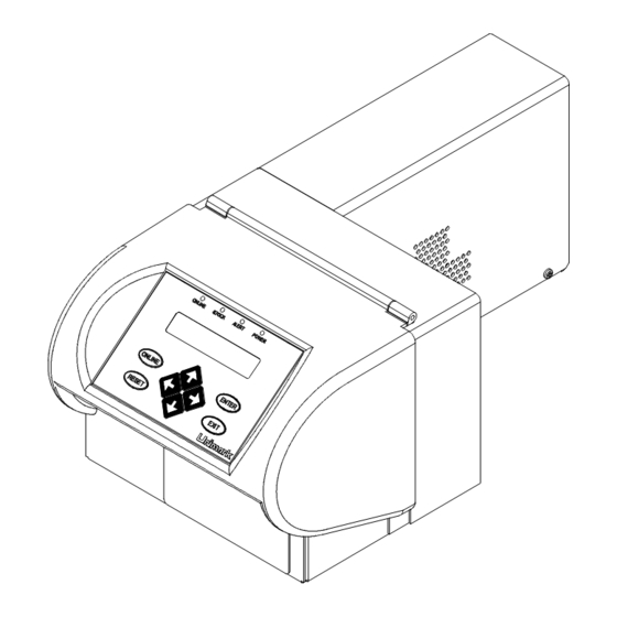
Page 7: Front Panel
The new firmware function was designed to prevent operators from accidentally changing the display contrast to minimum and being mistaken for a unit fault condition. Page 7 of 38 71U-1415-100K; REV E ET6000 Operator’s Manual... -
Page 8: Basic Operator Level Menu
(Bag Tag, Boarding Pass, Cargo Tag are standard Unimark defaults). ws some possible defaul t document types provided by Unimark. Not available on all versions. Others may be add ed by the customer through the se rvice menu or provided by Unimark from the factory per customer definition. -
Page 9: Adjustments Menu
Print Direction adjusts for whethe r stock is loaded into the ET6000 leading or trailing edge fi rst. This parameter effectiv ly rotates the print image 180 degrees. -
Page 10: Service Menu
3. Service menu is password protected and may vary depending on the customer. 4. Selected Doc Type is the document type that has been selected by the operator and is currently active. ET6000 Operator’s Manual 71U-1415-100K; REV E Page 10 of 38... -
Page 11: Selected Stock Type Parameters Setup Menu (Service Sub Menu)
Print Speed 2-8 IPS Adjust Value Ladder BC 2-8 IPS Print Sample Print Speed Not all firmware versions support the options listed, such as print speed range and ladder speed. Page 11 of 38 71U-1415-100K; REV E ET6000 Operator’s Manual... -
Page 12: Host Setup Menu (Service Sub Menu)
4. Strip Line Feed and/or Carriage Return options allow the Unit to remove LF and CR characters from the received data stream. This is usually a very custom type option or feature, and may vary or be enhanced to look at other data sequences depending on the customer’s requirements. ET6000 Operator’s Manual 71U-1415-100K; REV E Page 12 of 38... -
Page 13: Comm Port Setup Menu (Service Sub Menu)
RTS/CTS None DSR/DTR Even Host Busy ON OFF Parity NONE Mark Space RTS/CTS DSR/DTR Host Online Data Bits XON/XOFF NONE Stop Bits Pacing Chars Enter Value Pacing Time Enter Value Page 13 of 38 71U-1415-100K; REV E ET6000 Operator’s Manual... - Page 14 10. Pacing Time determines the timeout period before the unit transmits the next set of pacing characters to the host.Host Online selects the control method to inform the Unit that the host is powered on and ready to communicate. ET6000 Operator’s Manual 71U-1415-100K; REV E...
-
Page 15: Tcp/Ip Setup Menu (Service Sub Menu)
Secondary DNS Enter Value Display DNS Server 1 Value Display View Registered DNS DNS Server 2 Value Display DNS Server 3 Value Host TCP Port Enter Value MAC Address Display Value Page 15 of 38 71U-1415-100K; REV E ET6000 Operator’s Manual... - Page 16 The MAC address is also known as the Ethernet address, hardware addre , node ad ess, IEEE ddress, OUI, and others. It is a 48 bit number unique t e o ach hernet adapter. ET6000 Operator’s Manual 71U-1415-100K; REV E Page 16 of 38...
-
Page 17: Atb Setup Menu (Service Sub Menu)
4. Template X,Y adjust moves templates left/right or up/down to allow alignment of the templates to AEA row/column coordinates. 5. BT CMD Sets Length is provided for backwards compatibility. Prior to AEA 95’ the BT command selected stock type but not length. Page 17 of 38 71U-1415-100K; REV E ET6000 Operator’s Manual... -
Page 18: Printer Setup Menu (Service Sub Menu)
T e adds a new document type to the menu. The parameters of the added document type will be given defaults based on t he pe of document selected. The Delete Doc Type allows the specified document type to be deleted from the ET6000. ET6000 Operator’s Manual 71U-1415-100K;... -
Page 19: Maintenance Menu (Service Sub Menu)
TOF Paper Detect Enter Value TOF Drive Level Enter Value TOF Back Sensitivity Enter Value TOF Back Drive Level Enter Value Erase AEA Flash Confirm Operation Test NetArm Comm Display Results Page 19 of 38 71U-1415-100K; REV E ET6000 Operator’s Manual... - Page 20 Prnhd Profile causes the ET6000 to measure the current resistance value of each of the 640 print head dot elements. The result is printed on a graph along with baseline resistance, high and low resistance tolerance markings. Note that the profile takes about 20 seconds to perform.
-
Page 21: Printer Information (Service Sub Menu)
D display: 2. Service Stock is the amount of stock printed (in cm) for the ET6000 since the last time the ET6000 was serviced by Unimark 3. Service Jams is the number of jams for the ET6000 since the last t... -
Page 22: Loading Stock
Unit). Position one provides a stationary path approximately 3.25” (82.55mm) wide for ATB type stocks. Position two provides a stationary path approximately 2.00” (50.8mm) wide for bag tag type stocks. ET6000 Operator’s Manual 71U-1415-100K; REV E Page 22 of 38... -
Page 23: Loading Fan-Fold Stock
Present Sensor (P he stock is ow aded and ready for pri nting. Page 23 of 38 71U-1415-100K; REV E ET6000 Operator’s Manual... -
Page 24: Loading Roll Stock
6. The stock will automatically be pulled in by the platen and detected by the Present Sensor (PS). 7. The stock is now loaded and ready for printing. Alignment Marks Thermal printing surface out Wound Out Stock Roll Shown ET6000 Operator’s Manual 71U-1415-100K; REV E Page 24 of 38... -
Page 25: Loading Stock With The Optional Dust Cover
The stock will automatically be pulled in by the platen and detected by the Present Sensor (PS). The stock is now loaded and ready for printing. Page 25 of 38 71U-1415-100K; REV E ET6000 Operator’s Manual... -
Page 26: Clearing Stock Jams
If the brush is damaged, replace the brush and or Unit immediately. Operating the Unit without an ESD static brush, or with a damaged brush, may result in reduced print head life. ET6000 Operator’s Manual 71U-1415-100K; REV E Page 26 of 38... -
Page 27: Thermal Print Head, Platen, And Sensors
(part of cleaning kit P/N 700-5020-000). Verify that all label stock, media residue, and any other contaminants are cleared from the print head. Unimark recommends cleaning the print head every fifth box of stock or 100 ,000 inches of rinting. -
Page 28: Replacing The Thermal Print Head
8.3 Replacing the Thermal Print Head 1. While the suspect print head is still installed, print the print head profile and configuration coupons. Retain for return to Unimark Products, LLC. with the suspect print head. 2. Power the Unit off. CAUTION: Print Hea d is sensitive to ESD. -
Page 29: Cleaning/Clearing The Present Sensor (Ps)
Verify they are clear of particles, paper stock, and dust. Use canned air to clear sensor. Do not use alcohol except to clean off adhered labels or adhesives. Page 29 of 38 71U-1415-100K; REV E ET6000 Operator’s Manual... -
Page 30: Cleaning/Clearing The Center Top Of Form Sensor (Tof)
Veri fy they are clear of particles, paper stock, and dust. Use canned air to clear sensor. Do not use alcohol except to clean off adhered labels or adhesives. ET6000 Operator’s Manual 71U-1415-100K; REV E Page 30 of 38... -
Page 31: Stock Cutter
7. If there is label stock on the blade, use 99% (or higher) isopropyl alcohol to clean it. Verify that all label stock, media residue, and any other contaminants clear from cutter mechanism. Note that the cutter blade is sharp. Page 31 of 38 71U-1415-100K; REV E ET6000 Operator’s Manual... -
Page 32: Troubleshooting
Verify that the display interface cable has not pulled out from the front bezel. If it has, power the Unit off and reinstall the cable. Verify that the Unit’s Online LED is lit and use the up and down arrow keys to adjust the display con trast. ET6000 Operator’s Manual 71U-1415-100K; REV E Page 32 of 38... -
Page 33: Basic Alert Messages
Call the CRS or Airline Host help desk for help. element number in the data where the Unit detected the error. “TK: Bad Elem ##” ERR3 will be returned to the host CRS. Page 33 of 38 71U-1415-100K; REV E ET6000 Operator’s Manual... - Page 34 FIGURE 11.1: L-Shaped Base Model 11.2 Roll Stock Model The roll stock model allows up to an 8” (20.32cm) stock roll to be mounted in the stock input area. FIGURE 11.2: Roll Stock Model ET6000 Operator’s Manual 71U-1415-100K; REV E Page 34 of 38...
- Page 35 The Unit input path is accessed by using the finger lift point on the dust cover door and swinging it open. The door sits on top of the Unit. FIGURE 11.4: Path Dust Cover Model Page 35 of 38 71U-1415-100K; REV E ET6000 Operator’s Manual...
- Page 36 When the Unit is in the online state, the up and down arrow keys can be used to vary the display contrast. After approximately 15 seconds of key inactivity, the current display contrast/intensity is saved to memory. ET6000 Operator’s Manual 71U-1415-100K; REV E...
- Page 37 Customer Service. Packaging – Use original packaging materials or equivalent. If not available, Unimark can provide at a small cost. Enter the RA # on the packing list and on the outside of the container in at least two locations for easy identification at Unimark.
- Page 38 Unimark hereunder by the purchaser for a defective product. In no event shall Unimark be liable to the purchaser for any damages resulting from or related to any failure or delay of Unimark in the delivery or installation of the computer hardware, supplies or software or in the performance of any services.
Need help?
Do you have a question about the ET6000 and is the answer not in the manual?
Questions and answers