Subaru SGX3500 Service Manual
Hide thumbs
Also See for SGX3500:
- Instructions for use manual (40 pages) ,
- Servise manual (35 pages) ,
- Instructions for use manual (37 pages)
Table of Contents
Advertisement
Quick Links
- 1 Table of Contents
- 2 1 Specifications..........................................................1
- 3 General Description......................................................4
- 4 Oil Sensor . ..........................................................22
- 5 Component Parts......................................................27
- 6 Troubleshooting. ......................................................40
- 7 Wiring Diagram .......................................................43
- Download this manual
Advertisement
Table of Contents

Related Manuals for Subaru SGX3500


Summary of Contents for Subaru SGX3500
- Page 1 SGX3500 SGX5000 SGX7500...
-
Page 2: Table Of Contents
8-3 AC VOLTAGE IS NORMAL AT NO-LOAD, BUT THE LOAD CANNOT BE APPLIED...............42 9. WIRING DIAGRAM .......................................................43 NOTE This Service Manual excludes information for engine. As for the total servicing information as a generator set, please refer in conjunction with the Subaru EX series OHC Engine Service Manual. 3- 3 -... - Page 3 SGX Specification sheet Model SGX3500 SGX5000 SGX7500E Emission Compliancy 49 state 49 state 49 state CSA Compliant Type Brush Type Brush Type Brush Type Voltage Regulation AVR Frequency 60HZ/Single 60HZ/Single 60HZ/Single Voltage 120/240 120/240 120/240 Max Output (watts) 3500 4900 7300 Max Amps 29.2/14.6 40.8/20.4 60.8/30.4 Rated Output (watts) 3200 4500 6700 Rated Amps 26.6/13.3 37.5/18.8 55.8/27.9 dba @ rated output (7 meters)
-
Page 4: Performance Curves
2. PERFORMANCE CURVES S GX 3500 4000 60Hz-240V 3500 3000 2500 2000 1500 1000 Vo lt age (v) Fr e qu e n c y (Hz) Ou t pu t (VA) C u rrent ( A ) S GX 5000 60Hz-240V 5000 4500... - Page 5 SGX7500 60Hz-240V 7500 7000 6500 6000 5500 5000 4500 4000 3500 3000 2500 2000 1500 1000 V ol ta g e (v ) F requency (H z) Outp ut ( V A ) C u r r e n t (A) - 3 -...
-
Page 6: General Description......................................................4
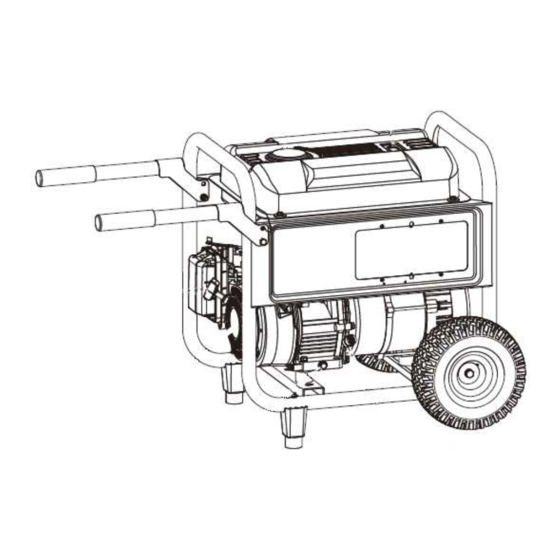
3. GENERAL DESCRIPTION - 4 -... - Page 7 CONTROL PANEL - 5 -...
-
Page 8: Serial Number
SERIAL NUMBER Serial number is stamped on the label stuck on the fuel tank. NOTE : Always specify serial number when inquiring about the generator or ordering spare parts in order to get correct parts and accurate service. PROD No. / SER No.(Label) CONSTRUCTION STATOR BOLT END COVER... -
Page 9: Range Of Applications
4. RANGE OF APPLICATIONS Generally, the power rating of an electrical appliance indicates the amount of work that can be done by it. The electric power required for operating an electrical appliance is not always equal to the output wattage of the appliance. The electrical appliances generally have a label showing their rated voltage, frequency, and power consumption (input wattage). - Page 10 570 W by 1.2 to 3 as explained in the ltem (3). 570 (W) × 1.2 to 3 = 684 (W) to 1710 (W) Applicable Wattage(approx. W) Applications SGX3500 SGX5000 SGX7500 Incandescent lamp, Heater...
- Page 11 NOTES : Wiring between generator and electrical appliances 1. Allowable current of cable Use a cable with an allowable current that is higher than the rated input current of the load (electrical appliance). If the input current is higher than the allowable current of the cable used, the cable will become excessively heated and deteriorate the insulation, possibly burning it out.
- Page 12 (6) AC Receptacle AC receptacles are used for taking AC output power from the generator. The rated current for each receptacle is shown as follows; C AUTION Be careful not to use the receptacles beyond the specified amperage limits to prevent circuit breaker trinpping.
- Page 13 When the AC circuit breaker turns off during operation, the generator is over loaded or the appliance is defective. Stop the generator immediately, check the appliance and / or generator for overloading or detect and have repaired as necessary by Subaru Industrial Power Products dealer or service shop. - 11 -...
- Page 14 Failure in connection may result in dea th, personal inj ury ,damage to generator, damage to a ppliances, damage to the building's wiring or fire. (a) When connecting a Subaru generator to a house wiring, generator output power must be taken from the 240V-4P receptacle.
- Page 15 - 13 -...
-
Page 16: Measuring Instruments.................................................14
5. MEASURING PROCEDURES 5-1 MEASURING INSTRUMENTS (1) VOLTMETER AC voltmeter is necessary. The approximate AC voltage ranges of the voltmeters to be used for various types of generators are as follows : 0 to 150 V : Type with an output voltage of 110 or 120 V 0 to 300 V : Type with an output voltage of 220, 230 or 240 V... - Page 17 (4) CIRCUIT TESTER Used for measuring resistance, etc. (5) MEGGER TESTER Used for measuring generator insulation resistance. Select one with testing voltage range of 500V. (6) TACHOMETER Use the contactless type tacho meter. - 15 -...
-
Page 18: Ac Output Measuring...................................................16
Rated voltage model A hot plate or lamp with a power factor of 1.0 240V-60Hz may be used as a load. Adjust the load and rpm. SGX3500 239-249 and check that the voltage range is as specified SGX5000 239-249 in the following table at the rated amperage and... - Page 19 An insulation resistance of 1 megohm or more is normal. (The original insulation resistance at the time of shipment from the factory is 10 megohm or more.) If it is less than 1 megohm, disassemble the generator and measure the insulation resistance of the stator, rotor and control panel individually.
-
Page 20: Checking Functional Members
AC CIRCUI BREAKER (Type 1) AC CIRCUIT BREAKER Frequency Rated output Max voltage Rated fault current SGX3500 250V 18.75A 3200VA SGX5000 60Hz 250V 4500VA SGX7500 250V 37.5A... -
Page 21: Stator. .............................................................19
20 °C (68 °F) (Ω) *Ambient temperature at 20℃(68°F ) ① SGX3500 SGX5000 SGX7500 FREQUENCY 60Hz RATED VOLTAGE 120V/240V AC WINDING 1 BLACK①-WHITE... -
Page 22: Brush. ..............................................................20
2) Cleaning Slip rings The slip ring surfaces must be uniformly bright. Slip rings showing black spots, excessive wear, or uneven wear must be repaired. A stained slip ring lowers generator efficiency and output voltage. Polish the slip rings with fine sandpaper while turning the rotor until rough spots disappear. - Page 23 A.V.R. in a normal generator, or mount a normal A.V.R. in a generator which fails to generate voltage. *Chacking table for analogue circuit tester (Resistance). (Ω)(R±20%) apply black ㊀ needle of the circuit tester SGX3500/5000 Black White-① White-② Blue-① Blue-②...
-
Page 24: Oil Sensor . ..........................................................22
6-8 OIL SENSOR (1) Disconnect wires coming from the sensor at the connection. (2) Loosen the sensor to remove it from the engine. (3) Plug the opening of oil filler hole (created after sensor is removed) with suitable means such as oil gauge. -
Page 25: Disassembly And Assembly
(8) Bind the wires and fuel pipes using wire bands as they have been done in original configuration. NOTE : As to detailed information for servicing procedures on engine portion, please refer to Subaru engine service manual for "EX series". 7-2 DISASSEMBLY PROCEDURES 7-2-1... - Page 26 (2) Loosen flange bolt and nut for the muffler stay. SGX3500 SGX5000 / 7500 5/16-18 x 38..1PC (SGX3500) 5/16-24 x 16..2PCS (SGX5000 / 7500) (3) Remove the muffler from Exhaust pipe. 7-2-3 CONTROL BOX (1) Remove the end cover.
- Page 27 NOTE) Before starting this work, make sure engine oil has been discharged. (3) Remove the two flange nuts (SGX3500: bolt) fixing rear cover onto the mount rubbers. M8 flange nut (bolts) . . . 2 pcs. (4) Remove the stator NOTE) The rear cover and the stator are clamped together by two of M6 bolts and nuts.
- Page 28 1. Pour engine oil into the center hole of rotor shaft. Fill with oil to the shaft end. 2. Prepare a bolt with the following thread size : M12 × 1.75 (SGX3500/5000/7500) 3. Apply a few turns of seal tape around the tip of the bolt 4.
-
Page 29: Component Parts......................................................27
7-3 COMPONENT PARTS - 27 -... - Page 30 - 28 -...
- Page 31 - 29 -...
- Page 32 - 30 -...
- Page 33 (3) Frame and accessories NOTE : Do not put fuel or lubricant in the generator before installing the feet, wheels and handles. INSTALLING THE WHEELS Wheels are provided to assist in moving the generator to the desired location and should be installed on the opposite side of the handle Locate the following items: 2 Bolts(3/8-16 ×4-1/4in.) 2 Washers(3/8 in.)
-
Page 34: Assembly Procedures...................................................32
7-4 ASSEMBLY PROCEDURES 7-4-1 ENGINE and FRAME (1) Attach the mount rubbers to the frame. Insert the setting tongue of mount rubber into the hole on the frame and tighten the nut from the bottom of the frame. M8 flange nut . . . 4 pcs. SGX3 5 0 0 SGX5 0 0 0 / 7 5 0 0 NOTE : The mount rubbers are selected to reduce vibration most effectively by model. - Page 35 NOTE : Tighten nut together with air cleaner bracket in air cleaner side. (SGX3500 / 5000) SGX3500 / 5000 M8 flange nut . . . 2 pcs. NOTE : Remove the air cleaner cover for easier installation. NOTE : When tightening the nuts, slightly lift the engine so that the weight is not applied to the mount rubbers.
- Page 36 7-4-3 FRONT COVER (1) Attach the front cover to the engine main bearing cover. SGX3500 5/16-24 flange bolt . . . 4 pcs. SGX 5000 / 7500 3/8-16 flange bolt . . . 4 pcs. 7-4-4 ROTOR (1) Wipe off oil, grease and dust from the tapered portion of engine shaft and matching tapered hole of rotor shaft.
- Page 37 (3) Fix the rear cover with flange bolts. flange bolt . . . 4 pc. NOTE : Tighten the bolts evenly and in turns. (SGX3500: Bolt) (4) Set the mount rubber bolts into the rear cover holes. Do not tighten the nut at this moment.
- Page 38 (10) Set stator cover with the claw inserted into slit and bent (2 pcs). (11) Attach the end cover to the rear cover. M5 × 8 bolt . . . 2 pcs. 7-4-6 MUFFLER and MUFFLER COVER (1) Mount the Exhaust pipe and the gasket on the cylinder head.
- Page 39 After that, tighten the nuts and flange bolts. M8 flange nuts . . . 2 pcs. (exhaust pipe) 5/16-24 x 16 flange bolt . . . 2 pcs. SGX3500 5/16-18 x 38 bolt, nut and washer (1pc). (4) Assemble the duct.
- Page 40 7-4-7 FUEL TANK (1) Hand tighten the strainer screw as far as it will go, loosen it again by one or two rotations (fuel outlet faces down), then tighten the lock nut. (2) Mount the fuel tank on the frame. M6 x 25 mm flange bolt .
-
Page 41: Checking, Disassembly And Reassembly Of The Control Panel......................39
7-4-8 CONTROL BOX ASSY (1) Pass wires drawn out generator and engine to the control box. (2) Connect the wires coming from the control panel with wires coming from generator and engine. NOTE : Connect the wires of the same color. (3) Mount the control panel together with the control box (Control box Assembly) onto the frame. -
Page 42: Troubleshooting. ......................................................40
8. TROUBLESHOOTING 8-1 NO AC OUTPUT 8-1-1 CHECKING STATOR (1) Remove control panel and disconnect stator wires at the connectors. (2) Measure the resistance between terminals on stator leads. Refer to Table of Section 6-3 STATOR for normal resistance. If stator is faulty, replace it with a new one. (3) Check the insulation resistance between stator core and each stator lead using a megger tester. -
Page 43: Ac Voltage Is Too High Or Too Low.........................................41
2) Cleaning Slip rings The slip ring surfaces must be uniformly bright. Slip rings showing black spots, excessive wear, or uneven wear must be repaired. A stained slip ring lowers generator efficiency and output voltage. Polish the slip rings with fine sandpaper while turning the rotor until rough spots disappear. -
Page 44: Ac Voltage Is Normal At No-Load, But The Load Cannot Be Applied...............42
8-3 AC VOLTAGE IS NORMAL AT NO-LOAD, BUT THE LOAD CANNOT BE APPLIED. 8-3-1 CHECK THE ENGINE SPEED. If the engine speed is low, adjust it to the rated r.p.m. *Refer to Step 8-2-1 for engine speed adjustment. 8-3-2 CHECK THE TOTAL WATTAGE OF APPLIANCES CONNECTED TO THE GENERATOR. Refer to Section 4 “RANGE OF APPLICATIONS”... -
Page 45: Wiring Diagram .......................................................43
9. WIRING DIAGRAM SGX3500 - 43 -... - Page 46 - 44 -...
Need help?
Do you have a question about the SGX3500 and is the answer not in the manual?
Questions and answers