Sign In
Upload
Download
Table of Contents
Contents
Add to my manuals
Delete from my manuals
Share
URL of this page:
HTML Link:
Bookmark this page
Add
Manual will be automatically added to "My Manuals"
Print this page
×
Bookmark added
×
Added to my manuals
Manuals
Brands
Subaru Manuals
Portable Generator
RGV12100
Instructions for use manual
Subaru RGV12100 Instructions For Use Manual
Hide thumbs
Also See for RGV12100
:
Specifications
(7 pages)
1
2
Table Of Contents
3
4
5
6
7
8
9
10
11
12
13
14
15
16
17
18
19
20
21
22
23
24
25
26
27
28
29
30
31
32
33
34
35
36
37
38
39
40
41
42
43
page
of
43
Go
/
43
Contents
Table of Contents
Troubleshooting
Bookmarks
Table of Contents
Air Index
Table of Contents
Safety Precautions
Engine Oil
Specifications
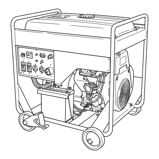
Components
Pre-Operation Checks
Check Engine Fuel
Battery Installation
Operating Procedures
Control Panel
Using Electric Power
Wattage Information
Spark Arrester
Maintenance Schedule
How-To" Maintenance
Cleaning and Adjusting Spark Plug
Cleaning Fuel Strainer
Preparation for Storage
Troubleshooting
Wiring Diagram
Optional Parts
Advertisement
Quick Links
1
Engine Oil
2
Specifications
3
Operating Procedures
4
Wattage Information
5
How-To" Maintenance
6
Troubleshooting
7
Wiring Diagram
8
Optional Parts
Download this manual
3ZZ9020236
SUBARU Generator
Table of
Contents
Previous
Page
Next
Page
1
2
3
4
5
Advertisement
Table of Contents
Need help?
Do you have a question about the RGV12100 and is the answer not in the manual?
Ask a question
Questions and answers
Related Manuals for Subaru RGV12100
Portable Generator Subaru RGx4800 Specifications
Robin generator brochure (7 pages)
Portable Generator Subaru R1100 Service Manual
Subaru generators service manual (57 pages)
Portable Generator Subaru ROBIN RGD3300H Instructions For Use Manual
(43 pages)
Portable Generator Subaru RGX2900 Generator User Manual
Subaru robin power products portable generator - power generator user manual (31 pages)
Portable Generator Subaru RGX2900 Instructions For Use Manual
Generator (41 pages)
Portable Generator Subaru RGX2900 Service Manual
(52 pages)
Portable Generator Subaru RGX6500/E Instructions For Use Manual
(41 pages)
Portable Generator Subaru RGV13100T Instructions For Use Manual
(43 pages)
Portable Generator Subaru Robin R1700i Service Manual
(52 pages)
Portable Generator Subaru RG3200iS Instructions For Use Manual
(28 pages)
Portable Generator Subaru RG4300iS Instructions For Use Manual
(28 pages)
Portable Generator Subaru Robin RG2800iS Instructions For Use Manual
(28 pages)
Portable Generator Subaru RGX3000 Service Manual
(64 pages)
Portable Generator Subaru Robin RGX7100 Instructions For Use Manual
(44 pages)
Portable Generator Subaru SGX3500 Service Manual
(46 pages)
Portable Generator Subaru WORMS LEADER 10500 XL21 Instructions For Use Manual
(24 pages)
This manual is also suitable for:
Rgv13100t
Table of Contents
Print
Rename the bookmark
Delete bookmark?
Delete from my manuals?
Login
Sign In
OR
Sign in with Facebook
Sign in with Google
Upload manual
Upload from disk
Upload from URL


Need help?
Do you have a question about the RGV12100 and is the answer not in the manual?
Questions and answers