Table of Contents
Advertisement
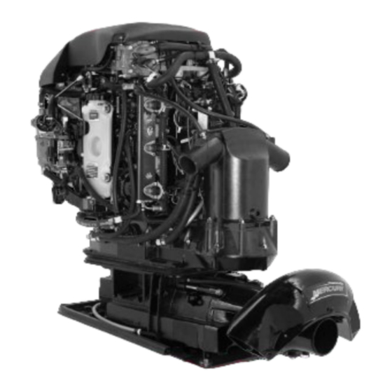
250 HP Jet Drive Installation Manual
Pre-delivery Preparation Instructions Must Be Performed Before Delivering Boat to the Product Owner.
After Completing Installation, These Instructions Should Be Placed with the Product for the Owner's Future Use.
The United States Coast Guard does not have a method to determine the maximum recommended horse-
power for Inboard Jet Boats. Therefore, it is the responsibility of the boat manufacturer to install the Mercury
Jet Drive, as well as any other Jet Drive model, in a boat which has been determined to be of suitable size,
weight, construction, and hull configuration for the power chosen. The Mercury Jet Drive, in particular, brings
a new level of performance to the jet boat category and is capable of propelling many hulls at speeds exceed-
ing 50 miles per hour.
In selecting the proper Jet Drive package for a particular application, please consider the overall performance
capability of the craft. Your boat may react to and handle differently with each Jet Drive model.
PLEASE carefully test and evaluate the overall handling characteristics of the boat package before
distribution for sale.
If you have application or installation questions, please contact your Mercury Marine OEM Sales Coordinator.
The Sales Coordinator will arrange to provide the necessary assistance.
Please assess your boat's performance completely before making the Jet Drive model selection. Safe boat-
ing is good for everyone.
Table of Contents
. . . . . . . . . . . . . . . . . . . . . . . . . .
. . . . . . . . . . . . . . . . . . . . . . . . . .
. . . . . . . . . . . . . . . . . . . . . . . . .
. . . . . . . . . . . . . . . . . . . . . . . . . . .
. . . . . . . . . . . . . . . . . . . . . . . . . . .
. . . . . . . . . . . . . . . . . . . . . . . . . . . . . .
Quicksilver Instrumentation,
. . . . . . . . . . . . . . . . . . . . . . . . . . . . .
. . . . . . . . . . . . . . . . . . . . . . . . . .
90-10240040 DECEMBER 2003
NOTICE to COMMISSIONING DEALER
NOTICE to INSTALLER
NOTICE to INSTALLER
. . . . . . . . . . . . . . . . . . . . . .
. . . . . . . . . . . . . . . . . . . . .
. . . . . . . . . . . . . . . . . . . . .
. . . . . . . . . . . .
. . . . . . . . . . . . . . . . . . . . . .
. . . . . . . . . . . . . . . .
. . . . . . . . . . . . . . . . . . .
. . . . . . . . . . .
. . . . . . . . . . . . . . . . .
10
. . . . . . . . . . . .
10
. . . . . . . . . . . . . . . . . . . .
. . . .
12
. . .
13
. . . . . . . . . . . . . . . . . . . . .
14
. . . . . . . . . . . .
15
15
16
2
2
3
3
3
Battery Cable and Remote Wiring Harness
4
4
4
5
6
7
8
9
9
. . . . . . . . . . . . . . . . . . . . . . . . . . . . . . . .
. . . . . . . . . . . . . . . . . . . . . . . . . . . . . . . . .
11
. . . . . . . . . . . . . . . . . . .
. . . . . . . . . . . . . . . . . . . . . . .
. . . . . . . . . . . . . . . . . . . . . . . .
. . . . . . . . . . . . . . . . . . . . . . . . . . . . . . .
. . . . . . . . . . . . . . . . . . . .
. . . . . . . . . . . . . . . . . . . . . . . . . .
. . . . . . . . . . . . . . . . . . . . . . . .
. . . . . . . . . . . . . . . . . . . . . . .
. . . . . . . . . . . . . . . . . . . .
. . . . . . . . . . . . . . . . . . . . . .
. . . . . . . . . . . . . .
. . . . . . . . . . . . . . . . . . . . . . .
. . . . . . . . . . . . . . . . . .
. . . . . . . . . . . .
. . . . . . . . . . . . . . . . . . . . . . . . . . . . . . .
. . . . . . . . . . . . . . . . . . . . . . .
20
23
27
.
28
29
30
31
33
34
36
38
38
39
40
40
. . . .
40
41
42
43
. . . . . . . . .
44
45
Page 1
Advertisement
Table of Contents

Related Manuals for Mercury 250 Jet Drive


Summary of Contents for Mercury 250 Jet Drive
-
Page 1: Table Of Contents
250 HP Jet Drive Installation Manual NOTICE to COMMISSIONING DEALER Pre-delivery Preparation Instructions Must Be Performed Before Delivering Boat to the Product Owner. NOTICE to INSTALLER After Completing Installation, These Instructions Should Be Placed with the Product for the Owner’s Future Use. -
Page 2: General Information
250 HP JET DRIVE INSTALLATION MANUAL General Information Notice to Installer Throughout this publication, Warnings and Cautions (accompanied by the International Hazard Symbol) are used to alert the installer to special instructions concerning a particular service or operation that may be hazardous if performed incorrectly or carelessly. ––... -
Page 3: Torque Specifications
250 HP JET DRIVE INSTALLATION MANUAL Torque Specifications NOTE: Tighten all fasteners, not listed, securely. 10 mm Fasteners (Powerhead to Pump) 47 Nm (35 lb ft) Reverse Stop Screw 14 Nm (120 lb in.) Forward Stop Screw 14 Nm (120 lb in.) Ride Plate-to-Pump Screws 8.5 Nm (75 lb in.) -
Page 4: Boat Construction
250 HP JET DRIVE INSTALLATION MANUAL Cable Length Cable Gauge Up to 1.1 m (3-1/2 ft) 4 (25mm 1.1-1.8 m (3-1/2 - 6 ft) 2 (35mm 1.8-2.3 m (6 - 7-1/2 ft) 1 (50mm 2.3-2.9 m (7-1/2 - 9-1/2 ft) 0 (50mm 2.9-3.7 m (9-1/2 - 12 ft) -
Page 5: Fuel Delivery System
250 HP JET DRIVE INSTALLATION MANUAL 59216 From Waterline to Top of Transom From Highest Point on Expansion Chamber to Top of Transom (a) minus (b) = (c) Waterline at Rest (at Maximum Load) Model c = (a) minus (b) Jet Drive (c) must be 203 mm (8 in.) or more. -
Page 6: Instrumentation
250 HP JET DRIVE INSTALLATION MANUAL 8. Vapor separator must be vented to fuel tank. Vent hose must comply with U.S. Coast Guard/ABYC regulations. Instrumentation CAUTION If a fused accessory panel is to be used, it is recommended that a separate circuit (properly fused) be used from the battery to the fuse panel with sufficient wire size to handle the intended current load. -
Page 7: Remote Control And Cables
250 HP JET DRIVE INSTALLATION MANUAL Remote Control and Cables The remote control must provide the following required features: Start in gear protection Neutral RPM limit at 2,000 RPM Note: This applies to dual lever remote controls as well as single lever remote controls. -
Page 8: Steering Helm And Cable
250 HP JET DRIVE INSTALLATION MANUAL Steering Helm and Cable STEERING HELM The steering helm must limit steering cable travel to 88.9 mm 2.5 mm (3-1/2 in. 1/8 in.). WARNING Failure to limit steering cable travel at the helm could pre-load the cable resulting in premature failure of a steering component causing loss of steering. -
Page 9: Wiring Diagram
250 HP JET DRIVE INSTALLATION MANUAL Wiring Diagram Instrumentation, Typical Analog Installation Shown NOTE: Refer to gauge manufacturer’s instructions for specific connections. a - Temperature Gauge b - Key Switch c - Tachometer Gauge d - Emergency Stop Switch e - Tachometer Harness (P/N 84-86396A8) (Not Included... -
Page 10: Wiring For Smartcraft Gauges
250 HP JET DRIVE INSTALLATION MANUAL Wiring for SmartCraft Gauges WIRING CONNECTIONS TO PADDLE WHEEL SPEED SENSOR, OIL TANK AND FUEL TANK IMPORTANT: DO NOT connect the Black/Orange wire to the fuel tank sensor when there is a engine battery ground strap connected to the fuel tank or sender assembly. -
Page 11: Typical System Layouts - Single Engine Product Configurations
250 HP JET DRIVE INSTALLATION MANUAL Typical System Layouts – Single Engine Product Configurations Speedometer and Tachometer (CAN) NOTE: CAN Type Gauges Can only be used on 2002 Model Year and newer V-6 models that are equipped for SmartCraft Tachometer... -
Page 12: Wiring Information For Can Type Gauges
250 HP JET DRIVE INSTALLATION MANUAL Wiring Information for CAN Type Gauges REQUIREMENTS SmartCraft communications are via the Controller Area Network (CAN), electrically imple- mented on a twisted pair of wires. Note: SmartCraft harnesses include other signals besides CAN. The maximum distance between any two modules on the SmartCraft bus is 40 meters (130 feet). -
Page 13: Wiring Accessories For Can Type Gauges
250 HP JET DRIVE INSTALLATION MANUAL Wiring Accessories for CAN Type Gauges Junction Boxes Junction Box Junction Box 8 Way 6 Way Weather Cap Terminator/Resistor 4 Way 859318T-2 859318T-1 878492A4 878492A6 878492A8 * For correct placement on these terminator/resistors, refer to Wiring Installation Guidelines preceding and Typical Installation configurations following. -
Page 14: Typical Installation Configurations For Can Type Gauges
250 HP JET DRIVE INSTALLATION MANUAL Typical Installation Configurations CAN Type Gauges NOTE: The typical installation configurations shown on this page and the next few pages are the lowest cost solutions. Other solutions are also possible. See Page 15 for general guidelines. -
Page 15: Mercury Jet Drive Hull Dimensions
250 HP JET DRIVE INSTALLATION MANUAL Mercury Jet Drive Hull Dimensions HULL OPENING The pump to powerhead opening in the hull is the most important factor to consider in a Jet Drive installation. There are three areas of concern: 1. Location (a) of the pump to powerhead hull opening relative to the boat bottom for proper ride plate seal fit. -
Page 16: Installing Jet Pump
250 HP JET DRIVE INSTALLATION MANUAL Installing Jet Pump CAUTION The hull opening dimensions are critical for proper sealing between Jet Pump and boat. Measure cutout thickness and overall dimensions before attempting a Jet Pump installation. 1. Install tunnel grommet in cut-out of boat by gluing front portion of grommet to tunnel with Loctite 454 or equivalent. - Page 17 250 HP JET DRIVE INSTALLATION MANUAL 2. Install thru-hull fittings and bellows assemblies. Tighten securely after pump is secured in hull. Thru-Hull Fitting, and Bellows Assembly Thru-Hull Fitting and Nut Clamp Bellows Slit Adaptor 3. Route steering cable through the thru-hull fitting and bellows. Route cable through the port side flange of pump housing.
- Page 18 250 HP JET DRIVE INSTALLATION MANUAL 5. Route shift cable through the thru-hull fitting and bellows. Route cable through the star- board side hole in flange of pump housing. 58144 Shift Cable IMPORTANT: Ensure that the shift lever in the control box is set for 76 mm (3 in.) of travel.
- Page 19 250 HP JET DRIVE INSTALLATION MANUAL 7. Install jet pump by pushing unit through opening in tunnel grommet. Ride plate seal should fit snug in boat tunnel without any gaps along perimeter. Jet Pump Tunnel Grommet 8. Install gasket and O-ring seal on jet pump.
-
Page 20: Steering Cable Adjustment
250 HP JET DRIVE INSTALLATION MANUAL Steering Cable Adjustment 1. Slide bellows assembly over cable and thread on cable completely. Do not tighten. 54456 Bellows 2. Thread cable end adaptor on steering cable 14 turns (to allow for adjustment). 54902... - Page 21 250 HP JET DRIVE INSTALLATION MANUAL 3. Center rudder assembly on nozzle. 4. Center steering wheel by turning wheel lock to lock and positioning wheel midway between locks. 5. Adjust cable end adaptor until thru-hole in adaptor lines up with threaded hole in steering arm.
- Page 22 250 HP JET DRIVE INSTALLATION MANUAL 10. Apply perfect seal to end threads. Perfect Seal 11. Turn bellows nut out and tighten against cable end adaptor. 54908 Bellows Clamp Bellows Nut Tight Against Jam Nut 12. Turn rudder to port to compress bellows as much as possible. Push bellows over cable conduit and secure with bellows clamp.
-
Page 23: Shift Cable Adjustment
250 HP JET DRIVE INSTALLATION MANUAL Shift Cable Adjustment IMPORTANT: The shift cable MUST BE properly adjusted. The shift cable is adjusted so that the reverse gate is not pre-loaded against either the forward or reverse stop. Pre-load in either position may cause failure of the stop and/or premature wear of the shift cable or control box components. - Page 24 250 HP JET DRIVE INSTALLATION MANUAL 4. Loosen the locknuts and unfasten the top end of the shift cable retainer. NOTE: Locknuts do not have to be removed to open shift cable retainer. Loosen top nut 1 turn and loosen bottom nut until retainer...
- Page 25 250 HP JET DRIVE INSTALLATION MANUAL 6. Adjust shift cable as follows: a. Position the control box into forward position. b. Position the reverse gate against the forward stop. With the reverse gate at this position, adjust the cable barrel to fit into the barrel holder with slight tension of the reverse gate against the stop.
- Page 26 250 HP JET DRIVE INSTALLATION MANUAL 9. Secure bellows to thru-hull fitting with clamp. Slide slit adaptor over cable and push into bellows. Secure with clamp. Shift Cable, Thru-Hull Fitting, and Bellows Assembly Thru-Hull Fitting and Nut Clamp Bellows Slit Adaptor NOTE: Check for proper placement of slit adaptor around cable.
-
Page 27: Installing Powerhead
250 HP JET DRIVE INSTALLATION MANUAL Installing Powerhead 1. Install gasket on drive housing cover. 2. Install water inlet O-ring and driveshaft opening O-ring. 3. Lubricate drive shaft splines with Special Lubricant 101. Gasket Water Inlet O-Ring Drive Shaft Opening O-Ring Lubricate driveshaft splines with Special Lubricant 101 4. -
Page 28: Fuel Line And Fuel Vapor Vent Hose Connections
250 HP JET DRIVE INSTALLATION MANUAL Fuel Line and Fuel Vapor Vent Hose Connections 1. Connect fuel line to fuel inlet fitting, secure with U.S. Coast Guard approved hose clamp (183.532). 2. Vapor separator tank (VST) must be vented to fuel tank. Vent hose must comply with U.S. -
Page 29: Connections
250 HP JET DRIVE INSTALLATION MANUAL Battery Cables and Remote Wiring Harness Connections WARNING U.S. Coast Guard regulation #33 CFR 183.445 requires that the positive battery cable connection at the starter solenoid terminal be protected by either a boot or protective shield. -
Page 30: Throttle Cable Installation
250 HP JET DRIVE INSTALLATION MANUAL Throttle Cable Installation 1. Position remote control into neutral. 2. Attach throttle cable to the throttle lever. Secure with washer and locknut. Nylon Washer Locknut – Tighten locknut then back off locknut 1/4 turn 3. -
Page 31: Oil Injection Set-Up
250 HP JET DRIVE INSTALLATION MANUAL Oil Injection Set-Up 1. Mount the oil reservoir in a suitable location. Use the oil tank hold down kit provided. 2. Oil hoses must be arranged so they cannot become pinched, kinked, sharply bent or stretched during operation of the engine. - Page 32 250 HP JET DRIVE INSTALLATION MANUAL 5. Fill remote oil tank with the recommended oil listed in the Operation and Maintenance Manual. Tighten fill cap. 6. Remove cap and fill engine oil tank with oil. Reinstall the fill cap. Engine Oil Tank 7.
-
Page 33: Bilge Siphon Feature
250 HP JET DRIVE INSTALLATION MANUAL Bilge Siphon Feature The Jet Drive incorporates an automatic bilge siphoning feature. The bilge siphon is working whenever the engine is running above idle speeds. Maximum performance of the bilge siphon is realized above 3,000 RPM. A hose is attached to the jet pump nozzle. The hose is routed to the engine compartment and placed in the bilge. -
Page 34: Water By-Pass System
250 HP JET DRIVE INSTALLATION MANUAL Water By-Pass System The water by-pass system is designed to improve powerhead cooling at idle speed. 1. Locate the water by-pass components (provided). Thru-Hull Fitting Hose Clamp Brass Nut IMPORTANT: The thru-hull fitting must be correctly positioned in the boat transom as instructed in Step 3. - Page 35 250 HP JET DRIVE INSTALLATION MANUAL 5. Connect a water by-pass hose between engine fitting and thru-hull fitting. Secure con- nections with hose clamps. NOTE: Make sure the hose slopes at a minimum rate of 25 mm (1 in.) drop per 300 mm (12 in.) of hose.
-
Page 36: Installation Of Flushing Kit
250 HP JET DRIVE INSTALLATION MANUAL Installation of Flushing Kit 1. Attach flush hose to fitting in drive housing cover. Secure with hose clamp. IMPORTANT: Failure to secure flush hose to fittings, will allow water to fill boat. Flush Hose Hose Clamp 2. - Page 37 250 HP JET DRIVE INSTALLATION MANUAL CAUTION BEFORE mounting flush adapter bracket, route flush adapter and hose to selected mounting location. Hose routing MUST NOT INTERFERE with throttle and/or con- trol linkage. NOTE: Mount flush adapter bracket in an area of the motor compartment that has a mount- ing surface that is thicker than the depth of the mounting screws.
-
Page 38: Flushing Instructions
250 HP JET DRIVE INSTALLATION MANUAL Flushing Instructions WARNING DO NOT run engine on flushing kit above idle speeds. Damage to engine from over- heating, due to lack of water supply may occur. 1. With engine off, remove flush adapter plug and attach water hose. -
Page 39: Trim Plate Adjustment
250 HP JET DRIVE INSTALLATION MANUAL Trim Plate Adjustment The Jet Drive unit trim plate is factory set for general applications. Should a particular boat experience porpoising problems, the trim plate can be adjusted as follows: 1. Loosen both jam nuts on trim plate (one starboard and one port). -
Page 40: Exhaust System Installation
250 HP JET DRIVE INSTALLATION MANUAL Exhaust System Installation General Exhaust System Notes 1. Exhaust system application must meet ABYC standard P-1 for marine exhaust installations. 2. The entire exhaust system must meet 1309.99 kPa (190 p.s.i.) (1309.99 burst pressure. -
Page 41: Top View
250 HP JET DRIVE INSTALLATION MANUAL Top View 250 hp – 878147-A1 Muffler Assembly, Port [22.8 cm (9.0 in.)] with 7.6 cm (3.0 in.) Outlet Connection Piping between Expansion Chamber and Muffler must be made of 7.6 cm (3.0 in.) O.D. Tubing. Tubing must be either 5052 or 6061 (14 ga) alumi- num or type 304 (14 ga) stainless steel to protect against corrosion. -
Page 42: Aft View
250 HP JET DRIVE INSTALLATION MANUAL Aft View Alternate Installation – If rubber hosing is to be used for connection between the expansion chamber and the muffler, a inner sleeve made of 6061-T6, 14 ga. aluminum tubing must be used as a liner and secured with 2 stainless steel hose clamps p/n 54-815504 or equivalent. -
Page 43: Side View
250 HP JET DRIVE INSTALLATION MANUAL Side View This line represents the bottom edge of the muffler outlet tube. Measure to en- sure that the lowest possible location of the bottom edge of the muffler tubes never gets within 5.1 cm (2.0 in.) of the maximum depth waterline. -
Page 44: Side View Of Expansion Chamber Outlet Pipe And Exhaust Pipe Connection
250 HP JET DRIVE INSTALLATION MANUAL Side View of Expansion Chamber Outlet Pipe and Exhaust Pipe Connection A spacer must be used with all 7.6 cm (3.0 in.) tube applications. A spacer having a 6.73 cm (2.65 in.) I.D. and a 7.6 cm (3.0 in.) O.D. needs to be installed over the expansion chamber outlets. -
Page 45: Pre-Delivery Inspection
250 HP JET DRIVE INSTALLATION MANUAL Pre-delivery Inspection Check/ CHECK BEFORE RUNNING Applicable Adjust Water hose connection/torqued Idle:____________RPM Cover plate & adaptor plate Forward-Neutral-Reverse fasteners torqued operational Battery meets engine Steering operational throughout specification entire range Battery charged & secure...