Clarke BOOST 28 Operator's Manual
Hide thumbs
Also See for BOOST 28:
- Operator's manual (124 pages) ,
- Operator's manual (122 pages) ,
- Operator's manual (124 pages)
Table of Contents
Advertisement
Operator's
Manual
U.S. Patent No. 6,105,192; No. 6,557,207; No. 6,760,947; No. 5,383,251; & Patents Pending
READ THIS BOOK
CAUTION: Read the Operator's Manual before using the appliance.
This book has important information for the use and safe operation of this machine. Failure to read this
book prior to operating or attempting any service or maintenance procedure to your Clarke machine could
result in injury to you or to other personnel; damage to the machine or to other property could occur as
well. You must have training in the operation of this machine before using it. If operator(s) cannot read
this manual, have it explained fully before attempting to operate this machine.
Si Ud. o sus operadores no pueden leer el Inglés, se hagan explicar este manual completamente antes
de tratar el manejo o servicio de esta máquina.
All directions given in this book are as seen from the operator's position at the rear of the machine.
®
For new books write to: Clarke
, 2100 Highway 265, Springdale, Arkansas 72764.
®
Clarke
Form No. 71071A 9/05
Printed in the U.S.A.
Advertisement
Table of Contents

Subscribe to Our Youtube Channel
Related Manuals for Clarke BOOST 28


Summary of Contents for Clarke BOOST 28
- Page 1 This book has important information for the use and safe operation of this machine. Failure to read this book prior to operating or attempting any service or maintenance procedure to your Clarke machine could result in injury to you or to other personnel; damage to the machine or to other property could occur as well.
-
Page 2: Table Of Contents
Safety Instructions ..........................3 Introduction & Machine Specifications ......................5 Procedures for Transporting Machine ......................6 Symbols Used on Boost 28 ..........................8 Machine Control Panel ............................. 9 Machine Controls and Features ........................10 How to Prepare the Machine for Operation ...................... 11 How to Install the Batteries ........................ -
Page 3: Operator Safety Instructions
Failure to read the Owner's Manual prior to operating or attempting any service or maintenance procedure to your Clarke machine could result in injury to you or to other personnel; damage to the machine or to other property could occur as well. - Page 4 Do not use this machine as a step or furniture. Do not ride on this machine. CAUTION: Your machine warranty will be voided if anything other than genuine Clarke parts are used on your machine. Always use Clarke parts for replacement.
-
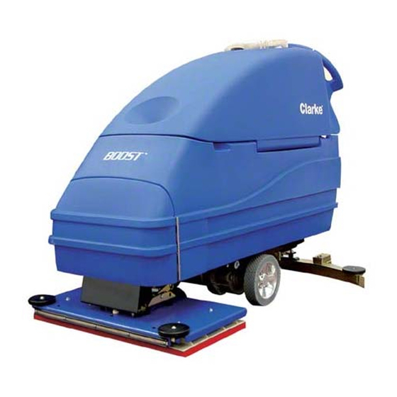
Page 5: Introduction & Machine Specifications
- all in one pass. The BOOST 28 comes complete with four - 6 volt batteries, one battery charger, a brush or a pad, and one operator’s manual. -
Page 6: Procedures For Transporting Machine
2. Make sure the ramp is clean and dry. 3. Put the ramp in position. 4. Remove squeegee assembly before loading. Clarke recommends that both the solution tank and recovery tank are empty before loading. 5. Turn key switch "ON" . - Page 7 Procedures For Transpoting (cont.) 10. Fasten the machine to the vehicle. Clarke recommends a strap over the top of the machine and a strap to keep the machine from rolling forward or backwards. If this is not done, there is a possibility of the machine toppling over.
-
Page 8: Symbols Used On Boost 28
SYMBOLS USED ON BOOST 28 Warning Solution Control Power Brush Up/Down Traverse Speed Control Warning Label Warning Label with parking without parking brake brake Page Clarke ® Operator's Manual - BOOST 28... -
Page 9: Machine Control Panel
To operating position and the middle position is transport shut brush motor off, place brush position switch in up to clear vacuum hose. position. Figure 3 ® Clarke Operator's Manual - BOOST 28 Page -9-... -
Page 10: Machine Controls And Features
NOTE: If the lever is left in the override position, the brake will not function with the Figure 5 key switch, and the machine will not operate. Figure 7 Figure 6 Page -10- Clarke ® Operator's Manual - BOOST 28... -
Page 11: How To Prepare The Machine For Operation
7. Close recovery tank by pulling up on the latch arm and then slowly lowering the tank. NOTE: Charge the batteries before using the machine. Figure 9 ® Clarke Operator's Manual - BOOST 28 Page -11-... -
Page 12: Battery Maintenance
Do not allow ammonia or bicar- bonate of soda to get into batteries. g. Neutralize any acid spills with ammonia or bicarbonate of soda. Page -12- Clarke ® Operator's Manual - BOOST 28... -
Page 13: How To Charge The Batteries (Remote Charger)
When recharging the batteries, keep the recovery tank open. After every 20 recharging cycles, check the level of the electrolyte and if necessary top off with distilled water. Figure 12C ® Clarke Operator's Manual - BOOST 28 Page -13-... -
Page 14: How To Charge The Batteries (On-Board Charger)
When recharging the batteries, keep the recovery tank open. After every 20 recharging cycles, check the level of the electrolyte and if necessary top off with distilled water. Page -14- Clarke ® Operator's Manual - BOOST 28... -
Page 15: How To Install The Brush Or Pad
3. Turn the key switch "OFF". 4. Go to the front of the machine and pull downward on Figure 14 the brush or pad until it releases from the flex plates. See figure 14. ® Clarke Operator's Manual - BOOST 28 Page -15-... -
Page 16: How To Operate The Machine
When filling machine from the rear, position clear drain hose against bracket and insert hose as shown in figure 18 Solution level can be viewed from the back of the machine. Figure 17A Figure 18 Figure 17 Page -16- Clarke ® Operator's Manual - BOOST 28... -
Page 17: Operating The Machine
10. To turn the machine, push the rear of the machine to the side. 11. When you stop the machine, turn the key switch "OFF", remove the key and set the parking brake (if equipped). ® Clarke Operator's Manual - BOOST 28 Page -17-... -
Page 18: How To Clean A Floor
Do not lower the squeegee. This will keep the vacuum motor off. Lower the brush or pad and scrub the floor. Scrub the floor again with additional solution and lower the squeegee. Pick up all the solution with the squeegee. Page -18- Clarke ® Operator's Manual - BOOST 28... -
Page 19: Maintenance
9. Check the installation of the squeegee and squeegee hose. Figure 22 10. Make sure the solution drain / level indicator hose is secure on the storage mount on the rear of the machine. ® Clarke Operator's Manual - BOOST 28 Page -19-... -
Page 20: Procedures To Perform At The End Of Work
Use a clean cloth and wipe the surface of the machine. Charge the batteries. See the instruction in the section of Figure 26 this book called “How To Charge The Batteries”. Page -20- Clarke ® Operator's Manual - BOOST 28... -
Page 21: Procedures To Perform Every Week
Clean the battery terminals. Reconnect the batteries. 3. Check the hoses for leaks, obstructions and other damage. 4. Use a grease gun to lubricate the dual casters. See figure 28. Figure 28 ® Clarke Operator's Manual - BOOST 28 Page -21-... -
Page 22: Maintenance For The Squeegee
31. WARNING: Maintenance and repairs must be done by authorized REAR BLADE personnel only . 0.06 (1.5 mm) Figure 31 WARNING: Electrical repairs must be done by authorized personnel only. Page -22- Clarke ® Operator's Manual - BOOST 28... -
Page 23: How To Center Or Off Set Brushhead
Maintenance cont. Consult your Clarke Authorized Service Person to do the service procedures. Use only genuine Clarke parts. How to Center or Offset the Brush Head The brush head on this machine can be centered or offset 1 inch to the right side of the machine. To center or offset the brush head, follow this procedure: Recommended tools: 3/8"... -
Page 24: Accessories
30069A Blade, Rear - Nitrile Solid 30082A Blade, Rear - Ribbed Orange 30086A Blade, Front - Ribbed Natural 30091A Blade, Front - Slit Grout 30080A Blade, Front - Ribbed Orange 30084A Page -24- Clarke ® Operator's Manual - BOOST 28... -
Page 25: How To Correct Problems In The Machine
The charger is damaged. charger. Check voltage of each cell while discharging. The battery is defective. Connect the batteries. The batteries are disconnected. Adjust Pressure. Brush is in heavy scrub setting. ® Clarke Operator's Manual - BOOST 28 Page -25-... - Page 26 Turn key or switch on. Batteries are unplugged. Check the battery connections. Battery terminals are dirty. Batteries are discharged Check battery gauge and recharge NOTE: If the problem continues consult an authorized service person. Page -26- Clarke ® Operator's Manual - BOOST 28...
-
Page 27: Section Ii - Parts And Service Manual
Section II Parts and Service Manual (71071A) U.S. Patent No. 6,105,192; No. 6,557,207; No. 6,760,947; No. 5,383,251; and patents pending. ® Clarke Operator's Manual - BOOST 28 Page -27-... -
Page 28: Final Assembly Drawing 9/05
Clarke ® Final Assembly Drawing 9/05 On-Board Charger Option 23 22 Page -28- Clarke ® Operator's Manual - BOOST 28... -
Page 29: Parts List
Nut, ¼-20 53851A Bushing 40740A Cord, Power 30640A Rear Cover 40512A Battery charger 77092A Label, Gases 77093A Label, Falling 70226A Label, Battery 10072A Parking Brake Assembly * See page 12 for installation. ® Clarke Operator's Manual - BOOST 28 Page -29-... -
Page 30: Recovery Tank Drawing
Clarke ® Recovery Tank Assembly Drawing 9/05 24 23 #40 Recommended Torque 175 + or - 5 inch pounds Page -30- Clarke ® Operator's Manual - BOOST 28... -
Page 31: Parts List
Motor, Vacuum, (2-Stage Option) 643418 Gasket 58533A Spacer 920797 962666 Screw, 10-24 x ¾ 920296 Nut, 10-24 Elastic 38020A Strap 839410 Valve Asm. (includes 23, 24, 25, 26, 27, 28) 70226A Label, Battery Installation ® Clarke Operator's Manual - BOOST 28 Page -31-... -
Page 32: Solution Tank Assembly Drawing
Clarke ® Solution Tank Assembly 9/05 Page -32- Clarke ® Operator's Manual - BOOST 28... -
Page 33: Parts List
Funnel (included w/Kit 10177A) 10177A Kit, Solution Fill (includes #18-51308A)(includes NI - 30162A) 53562A Components Clarke P/N Description Qty. 50081A Bowl, Filter 53563A Filter, Screen 53564A Upper Body 54369A Gasket, Bowl ® Clarke Operator's Manual - BOOST 28 Page -33-... -
Page 34: Rear Panel Assembly Drawing (Remote Charger)
® Clarke Rear Panel Assembly Drawing 9/05 Remote Charger 16 17 Page -34- Clarke ® Operator's Manual - BOOST 28... -
Page 35: Parts List
193951 Grommet, slotted, 8” 41811A Solenoid, Main 40157A Harness, Traverse 40169A Solenoid, Vacuum 962798 Screw, 10-24 x ½ 40132A Control, Traverse 30097A Insulator, Mylar 77093A Label, Falling Parts 77092A Label, Gases ® Clarke Operator's Manual - BOOST 28 Page -35-... -
Page 36: Rear Panel Assembly Drawing (On-Board Charger)
Clarke ® Rear Panel Assembly Drawing 9/05 On-Board Charger 16 17 21 20 Page -36- Clarke ® Operator's Manual - BOOST 28... -
Page 37: Parts List
Bracket, Right Hand Charger Mount 61777A Bracket, Left Hand Charger Mount 980982 Washer, #10 87007A Washer, Flat ¼" 85390A Screw, ¼ - 20 x 1 ¼ 77093A Label, Falling Parts 77092A Label, Gases ® Clarke Operator's Manual - BOOST 28 Page -37-... -
Page 38: Control Panel Assembly Drawing 9/05
Clarke ® Control Panel Assembly Drawing 9/05 11 12 32 31 15 16 15 16 Page -38- Clarke ® Operator's Manual - BOOST 28... -
Page 39: Parts List
Housing, Switch & Lever 30055A Lever, Switch 50961A Spring, Switch 40126A Switch, Forward/Reverse 80104A Screw, 10-32 x ½ SS Black Xylan 70219A Label, Key Switch 34264A Gasket, Panel 47708A ¼ F.I.M.Q.D. 47712A ¼ F.I.F.Q.D. ® Clarke Operator's Manual - BOOST 28 Page -39-... -
Page 40: Squeegee Lift Assembly Drawing 9/05
Clarke ® Squeegee Lift Assembly Drawing 9/05 Page -40- Clarke ® Operator's Manual - BOOST 28... -
Page 41: Parts List
Squeegee, Pivot Arm 81104A Nut, ¼ Nylock 60255A Bracket, Squeegee 60328A Mount, Squeegee 81112A Nut, 5/16-18 Thin ESNA SS Page 35 Cable, Squeegee Lift Page 35 Lift Handle Assembly 920346 Palnut 980651 Washer ® Clarke Operator's Manual - BOOST 28 Page -41-... -
Page 42: Squeegee Assembly Drawing 9/05
® Clarke Squeegee Assembly Drawing 9/05 Page -42- Clarke ® Operator's Manual - BOOST 28... -
Page 43: Parts List
Spacer, Squeegee 39” 30091A Blade, Front Ribbed 39” 80011A Screw, -16 x 3 81301A Nut, -16 Jam SS 34260B Gasket 25201A Knob 60358A Shim, Squeegee Wheel 61370A Weight 80280A Nut, Squeegee Backup ® Clarke Operator's Manual - BOOST 28 Page -43-... -
Page 44: Frame Axle Assembly Drawing 9/05
Clarke ® Frame Axle Assembly Drawing 9/05 Page -44- Clarke ® Operator's Manual - BOOST 28... -
Page 45: Parts List
Solution Tank 980205 Washer, 85734A Screw, -16 x 2 69639A Strap, Static 10135A Flange, Hub Kit *NOTE: 10135A (Flange, Hub Kit) contains 1 flange (hub), 2 snap rings, and 2 retaining keys. ® Clarke Operator's Manual - BOOST 28 Page -45-... -
Page 46: Brush Head Assembly Drawing
Clarke ® Brush Head Assembly Parts List 9/05 Page -46- Clarke ® Operator's Manual - BOOST 28... -
Page 47: Parts List
Guard, Front 962139 Screw, 1/4-20 x .625 Hex Cap 997004 Pad, Red, 32” 30708A Endcap 722030 Clamp, Hose 30707A Hose 40645A Housing 41601A Connectors 60236B Bracket, Brush Head 11062A Rubber Mounting Kit Clarke ® Operator's Manual - BOOST 28 Page -47-... -
Page 48: Optional Brake Assembly Drawing And Parts List
NOTE: Only use spacer (ref. #2) on transaxles that have a circular step and mounting nuts protruding from end of motor. The motor that uses the spacer can be identified by the motor brush caps protruding past the outside diameter of the motor. ® Page -48- Clarke Operator's Manual - BOOST 28... -
Page 49: Vacuum Motor Drawing And Parts List 9/05
18. STATIONARY FAN 51043A 51043A 19. ROTATING FAN 51044A 51044A 20. STATIONARY FAN 51045A 21. ROTATING FAN 50998A 22. FAN SHELL 51046A 51047A 23. WASHER 24. NUT 25. INSULATOR BRUSH CAP 51048A 51048A ® Clarke Operator's Manual - BOOST 28 Page -49-... -
Page 50: Transaxle Repair Parts
® Clarke Transaxle Drawing 9/05 Page -50- Clarke ® Operator's Manual - BOOST 28... -
Page 51: Battery Charger Drawing And Parts List 9/05
Strain Relief, D.C. Cord 747553 747553 D.C. Cord Assembly 51986A 51986A A.C. Cord Assembly 51974A 908947 Housing, Red 911470 911470 D.C. Plug Lock Key 795020 795020 * NOTE: Parts not available at this time. ® Clarke Operator's Manual - BOOST 28 Page -51-... -
Page 52: Connection Diagram 9/05
® Clarke Connection Diagram 9/05 Page -52- Clarke ® Operator's Manual - BOOST 28... -
Page 53: Electrical Schematic 9/05
® Clarke Electrical Schematic 9/05 ® Clarke Operator's Manual - BOOST 28 Page -53-... - Page 54 NOTES Page -54- Clarke ® Operator's Manual - BOOST 28...
- Page 55 29815 John R. Gilwilly Industrial Estate (810) 544-6300 Penrith Cumbria CA11 9BN American Lincoln ® / Clarke, Marietta, Georgia 30066 +44 1768 868 995 1455 Canton Road (770) 973-5225 ALTO France S.A. Strasbourg B.P. 44, 4 Place d’Ostwald F-67036 Strasbourg...
- Page 56 STATED WARRANTIES ARE IN LIEU OF ALL OTHER WARRANTIES, EXPRESSED OR IMPLIED Clarke's liability under this warranty is limited to repair of the product and/or replacement of parts and is given to purchaser in lieu of all other remedies, including INCIDENTAL AND CONSEQUENTIAL DAMAGES.
Need help?
Do you have a question about the BOOST 28 and is the answer not in the manual?
Questions and answers