
Related Manuals for Allied Telesis AT-x310-26FT


Summary of Contents for Allied Telesis AT-x310-26FT
- Page 1 Series Fast Ethernet Switches AT-x310-26FT AT-x310-26FP AT-x310-50FT AT-x310-50FP Installation Guide for Stand-alone Switches 613-001963 Rev. A...
- Page 2 Allied Telesis, Inc. has been advised of, known, or should have known, the...
-
Page 3: Electrical Safety And Emissions Standards
Electrical Safety and Emissions Standards This product meets the following standards. U.S. Federal Communications Commission Radiated Energy Note: This equipment has been tested and found to comply with the limits for a Class A digital device pursuant to Part 15 of FCC Rules. -
Page 4: Translated Safety Statements
Translated Safety Statements Important: Safety statements that have the symbol are translated into multiple languages in the Translated Safety Statements document at www.alliedtelesis.com/support. -
Page 5: Table Of Contents
Contents Preface ....................................11 Document Conventions ...............................12 Contacting Allied Telesis ..............................13 Chapter 1: Overview ................................ 15 Features ....................................16 x310 Models .................................16 10/100 Mbps Twisted Pair Ports ..........................16 10/100/1000 Mbps Twisted Pair Ports .........................16 Power Over Ethernet ..............................17 SFP Slots ..................................17 S1 and S2 Stacking Slots .............................17... - Page 6 Installing the Switch in an Equipment Rack ........................60 Chapter 4: Installing the Switch on a Wall ........................65 Installing the AT-x310-26FT Switch on a Wall ........................66 Positions of the Switch on a Wall..........................66 Recommended Minimum Wall Area Dimensions ......................66 Wall Guidelines................................
- Page 7 Figure 24: Minimum Wall Area Dimensions for the AT-x310-26FT Switch with the Front Panel on the Left......67 Figure 25: Minimum Wall Area Dimensions for the AT-x310-26FT Switch with the Front Panel on the Right .....67 Figure 26: Attaching the Brackets to the AT-x310-26FT Switch for Wall Installation ............69 Figure 27: Marking the Locations of the Bracket Holes on a Concrete Wall ................70...
- Page 8 Figures Figure 50: Switch Initialization Messages (Continued) ......................98 Figure 51: Switch Initialization Messages (Continued) ......................99 Figure 52: Connecting the Management Cable to the Console Port ..................101 Figure 53: User Exec Mode Prompt............................102 Figure 54: SHOW STACK Command ..........................102 Figure 55: Moving to the Global Configuration Mode ......................103 Figure 56: Confirmation Prompt for the NO STACK ENABLE Command ................103 Figure 57: Returning to the Privileged Exec Mode ......................103 Figure 58: Saving the Changes with the WRITE Command....................104...
- Page 9 Table 3: IEEE Powered Device Classes ..........................28 Table 4: Combo Port Pairs ..............................32 Table 5: LEDs on the 10/100Base-TX Ports on the AT-x310-26FT and AT-x310-50FT Switches ........36 Table 6: LEDs for the PoE 10/100Base-TX Ports on the AT-x310-26FP and AT-x310-50FP Switches ......37 Table 7: LEDs on the 10/100/1000Base-T Ports .........................39...
- Page 10 Tables...
-
Page 11: Preface
Layer 2+ Fast Ethernet switches. This preface contains the following sections: “Document Conventions” on page 12 “Contacting Allied Telesis” on page 13 Note This guide explains how to install the switches as stand-alone units. For instructions on how to install them in a stack configuration with ™... -
Page 12: Document Conventions
Preface Document Conventions This document uses the following conventions: Note Notes provide additional information. Caution Cautions inform you that performing or omitting a specific action may result in equipment damage or loss of data. Warning Warnings inform you that performing or omitting a specific action may result in bodily injury. -
Page 13: Contacting Allied Telesis
Series Installation Guide for Stand-alone Switches Contacting Allied Telesis If you need assistance with this product, you may contact Allied Telesis technical support by going to the Support & Services section of the Allied Telesis web site at www.alliedtelesis.com/support. You can find links for the following services on this page: ... - Page 14 Preface...
-
Page 15: Chapter 1: Overview
Chapter 1 Overview This chapter contains the following sections: “Features” on page 16 “Front and Back Panels” on page 19 “Management Panel” on page 22 “10/100Base-TX Twisted Pair Ports” on page 23 “10/100/1000Base-T Twisted Pair Ports” on page 25 ... -
Page 16: Features
Chapter 1: Overview Features The x310 Series Switches and their features are listed in this section: x310 Models Here are model names of the x310 Series switches: AT-x310-26FT AT-x310-26FP AT-x310-50FT AT-x310-50FP 10/100 Mbps Here are the basic features of the 10/100 Mbps twisted pair ports: Twisted Pair ... -
Page 17: Power Over Ethernet
Supports 1000Base-ZX SFP transceivers Note SFP transceivers must be purchased separately. For a list of supported transceivers, contact your Allied Telesis distributor or reseller. Note The SFP slots are paired with the 10/100/1000Base-T ports to form combo port pairs. For information, refer to “Combo 10/100/ 1000Base-T Ports and SFP Slots”... -
Page 18: Leds
Chapter 1: Overview LEDs Here are the port LEDs: Link/activity and duplex mode LEDs for the twisted pair ports on non-PoE switches Link/activity and PoE status LEDs for the twisted pair ports on PoE switches Link/activity LEDs for SFP and SFP+ slots ... -
Page 19: Front And Back Panels
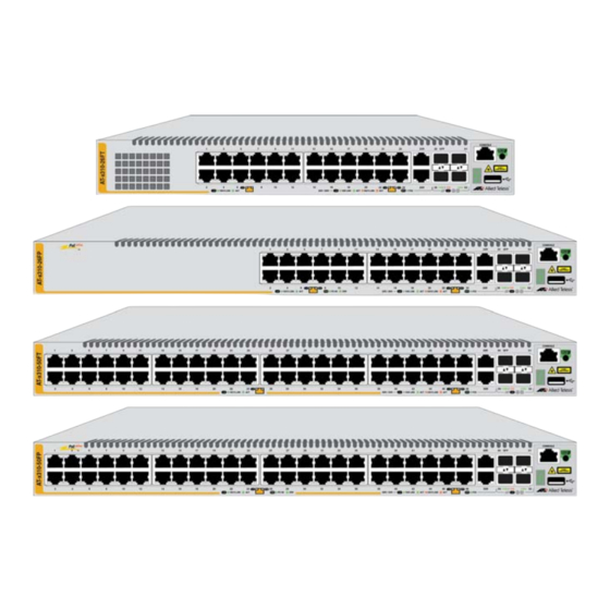
Figure 2 on page 20. AT-x310-26FT 10/100Base-TX Ports 10/100/1000Base-T Ports SFP Slots Stacking Slots Management Panel AT-x310-26FP 10/100Base-TX Ports with PoE 10/100/1000Base-T Ports SFP Slots Stacking Slots Management Panel Figure 1. Front Panels of the AT-x310-26FT and AT-x310-26FP Switches... -
Page 20: Figure 2: Front Panels Of The At-X310-50Ft And At-X310-50Fp Switches
Chapter 1: Overview AT-x310-50FT 10/100Base-TX Ports 10/100/1000Base-T Ports SFP Slots Stacking Slots Management Panel AT-x310-50FP 10/100Base-TX Ports with PoE 10/100/1000Base-T Ports SFP Slots Stacking Slots Management Panel Figure 2. Front Panels of the AT-x310-50FT and AT-x310-50FP Switches... -
Page 21: Figure 3: Back Panel Of The At-X310-26Ft Switches
Series Installation Guide for Stand-alone Switches The back panel of the AT-x310-26FT Switch is shown in Figure 3. AC Power Connector Figure 3. Back Panel of the AT-x310-26FT Switches The back panel of the AT-x310-26FP and AT-x310-50FP Switches is shown in Figure 4. -
Page 22: Management Panel
Chapter 1: Overview Management Panel Figure 6 identifies the components in the management panels on the x310 Series switches. Console Management Port eco-friendly button Switch ID LED USB Port Figure 6. x310 Series Management Panel... -
Page 23: 10/100Base-Tx Twisted Pair Ports
x310 Series Installation Guide for Stand-alone Switches 10/100Base-TX Twisted Pair Ports The x310 Series switches have 24 or 48 10/100Base-TX ports, depending on the model. Speed The ports can operate at either 10 or 100 Mbps. The speeds may be set manually using the management software or automatically with Auto- Negotiation (IEEE 802.3u), the default setting. -
Page 24: Maximum Distance
Chapter 1: Overview Maximum The ports have a maximum operating distance of 100 meters (328 feet). Distance Power Over The 10/100Base-TX ports on the AT-x310-26FP and AT-x310-50FP Switches support Power over Ethernet (PoE). The ports supply DC power Ethernet to network devices over the network twisted pair cables. The switches support PoE (IEEE 802.3af) and PoE+ (IEEE 802.3at). -
Page 25: 10/100/1000Base-T Twisted Pair Ports
x310 Series Installation Guide for Stand-alone Switches 10/100/1000Base-T Twisted Pair Ports The switches have two 10/100/1000Base-T ports. Note The 10/100/1000Base-T ports are paired with the SFP slots to form combo ports. For information, refer to “Combo 10/100/1000Base-T Ports and SFP Slots” on page 32. Speed The ports can operate at 10, 100, or 1000 Mbps. -
Page 26: Port Pinouts
Chapter 1: Overview Table 2. Twisted Pair Cable for the 10/100/1000Base-T Ports Cable Type 10Mbps 100Mbps 1000Mbps Standard TIA/EIA 568-B- compliant Category 3 shielded or unshielded cabling with 100 ohm impedance and a frequency of 16 MHz. Standard TIA/EIA 568-A- compliant Category 5 or TIA/ EIA 568-B-compliant Enhanced Category 5 (Cat 5e) shielded or... -
Page 27: Power Over Ethernet
x310 Series Installation Guide for Stand-alone Switches Power Over Ethernet The AT-x310-26FP and AT-x310-50FP Switches feature Power over Ethernet (PoE) on the 10/100Base-TX ports. PoE is used to supply power to network devices over the same twisted pair cables that carry the network traffic. -
Page 28: Powered Device Classes
Chapter 1: Overview Powered Device Powered devices are grouped into the five classes listed in Table 3. The classes are based on the amount of power the devices require. The Classes switches support all five classes. Table 3. IEEE Powered Device Classes Maximum Power Class Output from a Switch... -
Page 29: Port Prioritization
x310 Series Installation Guide for Stand-alone Switches Port If the power requirements of the powered devices exceed the switch’s power budget, the switch denies power to some ports based on a system Prioritization called port prioritization. You may use this mechanism to ensure that powered devices critical to the operations of your network are given preferential treatment by the switch in the distribution of power should the demands of the devices exceed the available capacity. -
Page 30: Wiring Implementation
Chapter 1: Overview Wiring The IEEE 802.3af standard defines two methods for delivering DC power over twisted pair cable by a PSE, such as a switch, to PDs. These Implementation methods, known as Alternatives A and B, identify which of the wires within the cables are to carry the DC power from the switches to the PDs. -
Page 31: Sfp Slots
The switches support a variety of short and long distance SFP modules. For a list of supported SFP modules, contact your Allied Telesis representative or visit our web site. Note The SFP slots and 10/100/1000Base-T ports are paired together to form combo port pairs. -
Page 32: Combo 10/100/1000Base-T Ports And Sfp Slots
For example, if you decide to use twisted pair port 25R on the AT-x310-26FT or AT-x310-26FP Switch, then you cannot use SFP slot 25. Or, if you choose to use SFP slot 49 on the AT-x310- 50FT or AT-x310-50FP Switch, then you cannot use the twisted pair port 49R. -
Page 33: Stacking Slots
x310 Series Installation Guide for Stand-alone Switches Stacking Slots The S1 and S2 slots on the front panel of the switch are used with special stacking transceivers to create a VCStack of up to four switches. The switches of a VCStack act as a single virtual unit. They synchronize their actions so that switching operations, like spanning tree protocols, virtual LANs, and static port trunks, span across all the units and ports. -
Page 34: Eco-Friendly Button
Chapter 1: Overview eco-friendly Button The eco-friendly button on the front panel of the switch is used to toggle the port LEDs on or off. You might turn off the LEDs to conserve electricity when you are not monitoring the device. You can also toggle the LEDs with the ECOFRIENDLY LED and NO ECOFRIENDLY LED commands in the Global Configuration mode of the command line interface. -
Page 35: Leds
LEDs are shown in Figure 8. Pair Ports Duplex Mode LED Link/Activity LED Duplex Mode LED Link/Activity LED Figure 8. LEDs for the 10/100Mbps Ports on the AT-x310-26FT and AT- x310-50FT Switches The LEDs are described in Table 5 on page 36. -
Page 36: Leds For The Poe 10/100Mbps Twisted Pair Ports
Chapter 1: Overview Table 5. LEDs on the 10/100Base-TX Ports on the AT-x310-26FT and AT-x310-50FT Switches State Description Solid Green A port has established a 100 Mbps link to a network device. Flashing A port is transmitting or receiving data at Green 100 Mbps. -
Page 37: Figure 9: Leds For The Poe 10/100Base-Tx Ports On The At-X310-26Fp And At-X310-50Fp Switches
x310 Series Installation Guide for Stand-alone Switches PoE LED Link/Activity LED PoE LED Link/Activity LED Figure 9. LEDs for the PoE 10/100Base-TX Ports on the AT-x310-26FP and AT-x310-50FP Switches The LEDs are described in Table 6. Table 6. LEDs for the PoE 10/100Base-TX Ports on the AT-x310-26FP and AT-x310-50FP Switches State Description... -
Page 38: Leds For The 10/100/1000Mbps Twisted Pair Ports
To turn on the LEDs, use the eco-friendly button. LEDs for the 10/ Ports 25R and 26R on the AT-x310-26FT and AT-x310-26FP Switches and ports 49R and 50R on the AT-x310-50FT and AT-x310-50FP 100/1000Mbps ‘Switches are 10/100/1000Base-T ports. The ports have two LEDs that Twisted Pair display link, activity and duplex mode information. -
Page 39: Figure 10: Leds For The 10/100/1000Base-T Ports
x310 Series Installation Guide for Stand-alone Switches Duplex Mode LED Link/Activity LED Duplex Mode Link/Activity LED Figure 10. LEDs for the 10/100/1000Base-T Ports The LEDs are described in Table 7. Table 7. LEDs on the 10/100/1000Base-T Ports State Description Solid Green A port has established a 1000 Mbps link to a network device. -
Page 40: Leds For The Sfp Slots
Chapter 1: Overview LEDs for the SFP The LEDs for the SFP slots are located between the slots, as shown in Figure 11. Each SFP slot has one LED. The left-hand LED is for the top Slots slot and the right-hand LED is for the bottom slot. SFP Slot LEDs Figure 11. -
Page 41: Switch Id Led
x310 Series Installation Guide for Stand-alone Switches Table 9. S1 and S2 Slot LEDs State Description Link/Activity The slot is empty, the stacking transceiver has not established a link to a network device, or the LEDs are turned off. To turn on the LEDs, use the eco-friendly button. -
Page 42: Figure 13: Switch Id Led
Chapter 1: Overview The switch is booting up. The switch has encountered a fault condition. The switch is operating as a stand-alone unit, with the ID number 0. The switch has an ID number of 1 to 4 as part of a VCStack. The dot in the lower right corner flashes when the switch accesses USB memory. -
Page 43: Usb Port
x310 Series Installation Guide for Stand-alone Switches USB Port The management panel has a USB port. You may use the port to store configuration files on flash drives and to restore configuration files to switches whose settings have been lost or corrupted, or to quickly configure replacement units. -
Page 44: Console Port
Chapter 1: Overview Console Port The Console port is used to conduct management sessions with the switch to configure its features and parameter settings. This type of management uses serial RS-232 and is commonly referred to as local or out-of-band management because it is not conducted over your network. To perform local management, you must be at the location of the switch and must use the management cable included with the switch. -
Page 45: Power Supply
x310 Series Installation Guide for Stand-alone Switches Power Supply The x310 Series switches come with one AC power supply. The back panels have one AC connector. The power supply is not field-replaceable, Refer to “Technical Specifications” on page 111 for the input voltage range. - Page 46 Chapter 1: Overview...
-
Page 47: Chapter 2: Beginning The Installation
Chapter 2 Beginning the Installation The chapter contains the following sections: “Reviewing Safety Precautions” on page 48 “Choosing a Site for the Switch” on page 52 “Unpacking the Switch” on page 53... -
Page 48: Reviewing Safety Precautions
Chapter 2: Beginning the Installation Reviewing Safety Precautions Please review the following safety precautions before beginning the installation procedure. Note Safety statements that have the symbol are translated into multiple languages in the Translated Safety Statements document at www.alliedtelesis.com/support. Warning Class 1 Laser product. - Page 49 x310 Series Installation Guide for Stand-alone Switches Warning Class I Equipment. This equipment must be earthed. The power plug must be connected to a properly wired earth ground socket outlet. An improperly wired socket outlet could place hazardous voltages on accessible metal parts. E4 Note Pluggable Equipment.
- Page 50 Chapter 2: Beginning the Installation Caution Risk of explosion if battery is replaced by an incorrect type. Replace only with the same or equivalent type recommended by the manufacturer. Dispose of used batteries according to the manufacturer’s instructions. Attention: Le remplacement de la batterie par une batterie de type incorrect peut provoquer un danger d’explosion.
- Page 51 x310 Series Installation Guide for Stand-alone Switches Warning Reliable earthing of rack-mounted equipment should be maintained. Particular attention should be given to supply connections other than direct connections to the branch circuits (e.g., use of power strips). E37 Warning To reduce the risk of electric shock, the PoE ports on this product must not connect to cabling that is routed outside the building where this device is located.
-
Page 52: Choosing A Site For The Switch
Chapter 2: Beginning the Installation Choosing a Site for the Switch Observe these requirements when planning the installation of the switch. If you plan to install the switch in an equipment rack, check to be sure that the rack is safely secured so that it will not tip over. Devices in a rack should be installed starting at the bottom, with the heavier devices near the bottom of the rack. -
Page 53: Unpacking The Switch
Series Installation Guide for Stand-alone Switches Unpacking the Switch All switches, except the AT-x310-26FT Switch, come with the components listed in Figure 15. If any item is missing or damaged, contact your Allied Telesis sales representative for assistance. One 2 m (6.6 ft) local management cable with RJ-45 (8P8C) and DB-9 (D-sub 9-pin) connectors. -
Page 54: Figure 16: Components Of The At-X310-26Ft Switch
Length: 29.6 mm (1 1/8 in.) Diameter: 6.0 mm (0.25 in) Two screws for wood or concrete walls: Length: 31 mm (1 1/4 in.) Width: 4.3 mm (1/8 in.) Power cord retaining clip Figure 16. Components of the AT-x310-26FT Switch... - Page 55 Series Installation Guide for Stand-alone Switches Note You should retain the original packaging material in the event you need to return the unit to Allied Telesis.
- Page 56 Chapter 2: Beginning the Installation...
-
Page 57: Chapter 3: Installing The Switch On A Table Or In An Equipment Rack
Chapter 3 Installing the Switch on a Table or in an Equipment Rack The procedures in this chapter are: “Selecting a Site for the Switch” on page 58 “Installing the Switch on a Table” on page 59 “Installing the Switch in an Equipment Rack”... -
Page 58: Selecting A Site For The Switch
Chapter 3: Installing the Switch on a Table or in an Equipment Rack Selecting a Site for the Switch Here are the site guidelines for the switch: The power outlet should be located near the switch and be easily accessible. -
Page 59: Installing The Switch On A Table
x310 Series Installation Guide for Stand-alone Switches Installing the Switch on a Table This section contains the procedure for installing the switch on a table or desk. Note The rubber feet on the bottom of the chassis should be left on for table installation. -
Page 60: Installing The Switch In An Equipment Rack
52. Here is the procedure for installing the switch in a 19-inch equipment rack. Caution The chassis may be heavy and awkward to lift. Allied Telesis recommends that you get assistance when mounting the chassis in an equipment rack. E28 1. -
Page 61: Figure 19: Installing Brackets On The At-X310-26Ft Switch
4. Attach the two rack mount brackets to the sides of the switch with the eight bracket screws that come with the unit. The AT-x310-26FT Switch comes with one short bracket and one long bracket. When installing the device in an equipment rack, Allied Telesis... -
Page 62: Figure 20: Attaching Brackets To The At-X310-26Fp, At-X310-50Ft, And At-X310-50Fp Switches
Chapter 3: Installing the Switch on a Table or in an Equipment Rack Figure 20. Attaching Brackets to the AT-x310-26FP, AT-x310-50FT, and AT-x310-50FP Switches... -
Page 63: Figure 21: Attaching Brackets To The At-X310-26Fp, At-X310-50Ft, And At-X310-50Fp Switches (Continued)
x310 Series Installation Guide for Stand-alone Switches Figure 21. Attaching Brackets to the AT-x310-26FP, AT-x310-50FT, and AT-x310-50FP Switches (Continued) -
Page 64: Figure 22: Mounting The Switch In An Equipment Rack
Chapter 3: Installing the Switch on a Table or in an Equipment Rack 5. While another person holds the switch in the equipment rack, secure it with standard equipment rack screws (not provided), as shown in Figure 22. Figure 22. Mounting the Switch in an Equipment Rack 6. -
Page 65: Chapter 4: Installing The Switch On A Wall
Chapter 4 Installing the Switch on a Wall The procedures in this chapter are: “Installing the AT-x310-26FT Switch on a Wall” on page 66 “Installing the AT-x310-26FP, AT-x310-50FT, and AT-x310-50FP Switches on a Wall” on page 73... -
Page 66: Installing The At-X310-26Ft Switch On A Wall
Figure 23. You may not install it with the front panel on Switch on a Wall the top or bottom. Figure 23. Positions of the AT-x310-26FT Switch on a Wall Recommended The wall location for the AT-x310-26FT Switch must provide adequate... -
Page 67: Figure 24: Minimum Wall Area Dimensions For The At-X310-26Ft Switch With The Front Panel On The Left
Figure 24. Minimum Wall Area Dimensions for the AT-x310-26FT Switch with the Front Panel on the Left Figure 25. Minimum Wall Area Dimensions for the AT-x310-26FT Switch... -
Page 68: Wall Guidelines
Chapter 4: Installing the Switch on a Wall Wall Guidelines Here are the guidelines to installing the AT-x310-26FT Switch on a wall. You may install the switch on a wall that has wooden studs. You may install the switch on a concrete wall. -
Page 69: Figure 26: Attaching The Brackets To The At-X310-26Ft Switch For Wall Installation
Position of the brackets if the switch is to be installed on the wall with the front panel on the right. Figure 26. Attaching the Brackets to the AT-x310-26FT Switch for Wall Installation 4. If you are installing the switch on a wall with wooden studs, use a stud finder to locate and mark with a pencil or pen the middle of a stud in the wall where you plan to install the switch. -
Page 70: Figure 27: Marking The Locations Of The Bracket Holes On A Concrete Wall
Chapter 4: Installing the Switch on a Wall 5. Have another person hold the switch on the concrete wall at the selected location for the device while you use a pencil or pen to mark the wall with the locations of the two screw holes in the brackets. Refer to Figure 27. -
Page 71: Figure 28: Installing The At-X310-26Ft Switch On A Wall
Series Installation Guide for Stand-alone Switches Allied Telesis recommends cleaning out the holes with a brush or compressed air. 8. Insert the two anchors into the holes. 9. Have another person hold the switch at the selected wall location while you secure it to the wall with the two provided screws. - Page 72 Chapter 4: Installing the Switch on a Wall This completes the procedure for mounting the AT-x310-26FT Switch on a wall. Go to Chapter 5, “Cabling the Networking Ports” on page 85 for instructions on how to attach the network cables.
-
Page 73: Installing The At-X310-26Fp, At-X310-50Ft, And At-X310-50Fp Switches On A Wall
x310 Series Installation Guide for Stand-alone Switches Installing the AT-x310-26FP, AT-x310-50FT, and AT-x310-50FP Switches on a Wall This section contains the instructions for installing the AT-x310-26FP, AT- x310-50FT, and AT-x310-50FP Switches on a wall. Position of the The switch may be installed on the wall with the front panel on the left or right, as shown in Figure 29. -
Page 74: Figure 30: Minimum Wall Area Dimensions For The Switch When The Front Panel Is On The Left
Chapter 4: Installing the Switch on a Wall the front panel is on the left. Figure 31 shows the recommended position of the device when the front panel is on the right. Figure 30. Minimum Wall Area Dimensions for the Switch When the Front Panel is on the Left Figure 31. -
Page 75: Positions Of The Brackets
Plywood Base for If you are installing the AT-x310-26FP, AT-x310-50FT, or AT-x310-50FP Switch on a wall that has wooden studs, Allied Telesis recommends using a Wall with a plywood base to attach the device to the wall. (A plywood base is not Wooden Studs required for a concrete wall.) Refer to Figure 33 on page 76. -
Page 76: Figure 33: Switch On A Plywood Base
Chapter 4: Installing the Switch on a Wall Wall Studs Wall Plywood Base Figure 33. Switch on a Plywood Base The plywood base allows you to mount the switch on two wall studs. Without the base, only one bracket could be attached to a stud. This is because the standard distance between two studs in a wall is 41 centimeters (16 inches) while the distances between the two brackets on the switches are 26.7 centimeters (10 1/2 inches) for the AT-x310-50FT... -
Page 77: Figure 34: Distances Between The Brackets On The At-X310-26Fp, At-X310-50Ft, And At-X310-50Fp Switches
x310 Series Installation Guide for Stand-alone Switches AT-x310-50FT Switch AT-x310-26FP and AT-x310-50FP Switches Figure 34. Distances Between the Brackets on the AT-x310-26FP, AT- x310-50FT, and AT-x310-50FP Switches The recommended minimum dimensions of the plywood base are listed here: Width: 50.8 centimeters (20 inches) ... -
Page 78: Wall Guidelines
Chapter 4: Installing the Switch on a Wall You should install the plywood base to the wall and then install the switch on the base. Refer to Figure 35. Plywood Wall Base Step 1: Install the Step 2: Install the plywood base to switch on the the wall. -
Page 79: Tools And Material
x310 Series Installation Guide for Stand-alone Switches You should not install the switch on a metal stud. Metal studs may not be strong enough to safely support the device. Tools and Here are the required tools and material for installing the switch on a wall: Material ... -
Page 80: Figure 36: Attaching The Brackets For Wall Installation For All Switches Except The At-X310-26Ft Switch
Figure 36. Attaching the Brackets for Wall Installation for All Switches Except the AT-x310-26FT Switch 3. Have another person hold the switch on the plywood base on the wall while you secure it with the two provided screws. Refer to Figure 37 on page 81. -
Page 81: Figure 37: Securing The Switch To The Plywood Base
x310 Series Installation Guide for Stand-alone Switches Figure 37. Securing the Switch to the Plywood Base This completes the procedure for mounting the switch on the wall. Go to Chapter 5, “Cabling the Networking Ports” on page 85, for instructions on how to connect the network cables to the ports on the switch. -
Page 82: Installing The Switch On A Concrete Wall
Chapter 4: Installing the Switch on a Wall Installing the To install the AT-x310-26FP, AT-x310-50FT, or AT-x310-50FP Switch on a concrete wall, perform the following procedure: Switch on a Concrete Wall 1. Perform steps 1 to 3 in “Installing the Switch in an Equipment Rack” on page 60 to remove the rubber feet from the bottom of the switch. -
Page 83: Figure 39: Installing The At-X310-26Fp, At-X310-50Ft, Or At-X310-50Fp Switch On A Wall
Prior to drilling, set the drill to hammer and rotation mode. The modes break up the concrete and clean out the hole. Allied Telesis recommends cleaning out the holes with a brush or compressed air. 6. Insert the two anchors into the holes. - Page 84 Chapter 4: Installing the Switch on a Wall This completes the procedure for mounting the switch on the wall. Go to Chapter 5, “Cabling the Networking Ports” on page 85, for instructions on how to connect the network cables to the ports on the switch.
-
Page 85: Chapter 5: Cabling The Networking Ports
Chapter 5 Cabling the Networking Ports This chapter contains the following procedures: “Cabling the Twisted Pair Ports” on page 86 “Installing SFP Transceivers” on page 88... -
Page 86: Cabling The Twisted Pair Ports
Chapter 5: Cabling the Networking Ports Cabling the Twisted Pair Ports Here are the guidelines to cabling the 10/100Base-TX and 10/100/ 1000Base-T twisted pair ports: The cable specifications for the 10/100Base-TX and 10/100/ 1000Base-T twisted pair ports are listed in Table 1 on page 24 and Table 2 on page 26, respectively. - Page 87 x310 Series Installation Guide for Stand-alone Switches that also support Auto-Negotiation for duplex modes. The default duplex mode setting of Auto-Negotiation is not appropriate for ports connected to network devices that do not support Auto-Negotiation and have a fixed duplex mode. You should disable Auto-Negotiation on those ports and set their duplex modes manually to avoid the possibility of duplex mode mismatches.
-
Page 88: Installing Sfp Transceivers
For more information, refer to “Combo 10/100/1000Base-T Ports and SFP Slots” on page 32. Your Allied Telesis sales representative can provide you with a list of supported transceivers for the units. The operational specifications and fiber optic cable requirements of the transceivers are provided in the documents included with the devices. -
Page 89: Installing Sfp Modules
x310 Series Installation Guide for Stand-alone Switches Installing SFP To install SFP transceivers in slots 25 and 26 of the 26-port switches or slots 49 and 50 of the 50-port switches, perform the following procedure: Modules 1. Remove the dust plug from a transceiver slot on the switch. Refer to Figure 40. -
Page 90: Figure 42: Removing The Dust Cover From An Sfp Transceiver
Chapter 5: Cabling the Networking Ports Note If you are ready to attach the fiber optic cable to the transceiver, continue with the next step. Otherwise, repeat steps 1 to 4 to install another SFP transceiver in the switch. 5. Remove the dust cover from the transceiver, as shown in Figure 42. Figure 42. -
Page 91: Figure 44: Connecting A Fiber Optic Cable To An Sfp Transceiver
x310 Series Installation Guide for Stand-alone Switches 7. Connect the fiber optic cable to the transceiver, as shown in Figure 44. The connector on the cable should fit snugly into the port, and the tab should lock the connector into place. Figure 44. - Page 92 Chapter 5: Cabling the Networking Ports...
-
Page 93: Chapter 6: Powering On The Switch
Chapter 6 Powering On the Switch This chapter contains the following procedures: “Powering On the Switch” on page 94 “Monitoring the Initialization Processes” on page 97 “Configuring the Switch for Stand-alone Operations” on page 100 “Specifying Ports in the Command Line Interface for Stand-alone Switches”... -
Page 94: Powering On The Switch
Chapter 6: Powering On the Switch Powering On the Switch Before powering on the switch, refer to “Power Specifications” on page 112 for the power specifications.To install the power cord retaining clip and power on the switch, perform the following procedure: 1. -
Page 95: Figure 46: Raising The Retaining Clip
x310 Series Installation Guide for Stand-alone Switches Figure 46. Raising the Retaining Clip 3. Connect the power cord to the connector. Refer to Figure 47. Figure 47. Plugging in the AC Power Cord 4. Lower the retaining clip to secure the power cord to the switch. Refer to Figure 48. - Page 96 Chapter 6: Powering On the Switch 5. Connect the other end of the power cord to an appropriate power source. Warning Power cord is used as a disconnection device. To de-energize equipment, disconnect the power cord. E3 Note Pluggable Equipment. The socket outlet shall be installed near the equipment and shall be easily accessible.
-
Page 97: Monitoring The Initialization Processes
\ \_ __/ /| ______ | | ______ | \ ____ / /______/\____\ \/ /____________/ Allied Telesis Inc. AlliedWare Plus (TM) v0.0.0 Current release filename: x310-1706_x950-latest.rel Original release filename: x310-1706_x950-20140206-1.rel Built: Thu Feb 6 01:14:24 NZdT 2014 hwclock:settimeofday: Invalid argument... -
Page 98: Figure 50: Switch Initialization Messages (Continued)
Chapter 6: Powering On the Switch Mounting static filesystems... Checking flash filesystem... Mounting flash filesystem... Checking for last gasp debug output... Checking NVS filesystem... Mounting NVS filesystem... Starting base/dbus... Starting base/syslog... Starting base/loopback... Starting base/poe_done... Starting base/sysctl... Received event poefw.done Starting base/portmapper... -
Page 99: Figure 51: Switch Initialization Messages (Continued)
x310 Series Installation Guide for Stand-alone Switches Received event vcs.elected-master 00:00:58 awplus-1 VCS[897]: Startup speed can be improved by adding 'no stack 1 to configuration 00:00:58 awplus-1 VCS[897]: Member 1 (eccd.6dc1.19ff) has become the Active Master Assigning Active Workload to HA processes: hsl, nsm, irdpd, lacpd, lopprotd, mstpd, rmond sflowd, authd, epsrd, lldpd, imi, imiproxyd Received event network.activated... -
Page 100: Configuring The Switch For Stand-Alone Operations
Chapter 6: Powering On the Switch Configuring the Switch for Stand-alone Operations After the switch has initialized its management software, examine the switch ID LED on the front panel and do one of the following: If the LED is displaying “0,” the installation procedure is complete. The switch is now ready for network operations as a stand-alone unit. -
Page 101: Figure 52: Connecting The Management Cable To The Console Port
x310 Series Installation Guide for Stand-alone Switches Figure 52. Connecting the Management Cable to the Console Port 2. Connect the other end of the cable to an RS-232 port on a terminal or PC with a terminal emulator program. 3. Configure the terminal or terminal emulator program as follows: ... -
Page 102: Disabling Vcstack
Chapter 6: Powering On the Switch Disabling To disable the VCStack feature to use the switch as stand-alone unit, perform the following procedure: VCStack Caution Disabling the VCStack feature requires resetting the switch. If the switch is already connected to a live network, some network traffic may be lost. -
Page 103: Figure 55: Moving To The Global Configuration Mode
x310 Series Installation Guide for Stand-alone Switches If the Operational Status is “Standalone Unit,” as shown in Figure 54 on page 102, the VCStack feature is active on the unit. You must disable it by performing the steps in the rest of this procedure before you can use the SFP+ stacking slots with regular SFP or SFP+ transceivers. -
Page 104: Figure 58: Saving The Changes With The Write Command
Chapter 6: Powering On the Switch awplus# write Building configuration ... [OK] awplus# Figure 58. Saving the Changes with the WRITE Command 9. Enter the REBOOT command to reboot the switch. 10. At the confirmation prompt, type “Y” for yes. 11. -
Page 105: Specifying Ports In The Command Line Interface For Stand-Alone Switches
x310 Series Installation Guide for Stand-alone Switches Specifying Ports in the Command Line Interface for Stand-alone Switches The command line interface in the management software on the switch has a parameter that you use to specify the individual ports. The parameter is the PORT parameter and Figure 59 shows its format. - Page 106 Chapter 6: Powering On the Switch...
-
Page 107: Chapter 7: Troubleshooting
This chapter contains suggestions on how to troubleshoot the switch if a problem occurs. Note For further assistance, please contact Allied Telesis Technical Support at www.alliedtelesis.com/support. Problem 1: The Switch ID LED on the front of the switch is off. - Page 108 Chapter 7: Troubleshooting Try connecting another network device to the twisted pair port with a different cable. If the twisted pair port is able to establish a link, then the problem is with the cable or the other network device. ...
- Page 109 The internal temperature of the switch has exceeded the normal operating range and the switch may shut down. Contact your Allied Telesis sales representative for assistance. Problem 8: The AT-x310-26FP or AT-3510-50FP Switch is not providing power to a PoE device.
- Page 110 Chapter 7: Troubleshooting is carried on pins 4, 5, 7, and 8 on the RJ-45 port, the same pins that carry the network traffic. The other mode, Alternative A, defines pins 1, 2, 3, and 6 as the power carriers. The AT-x310- 26FP and AT-3510-50FP Switches do not support Alternative A.
-
Page 111: Appendix A: Technical Specifications
Technical Specifications Physical Specifications Dimensions (H x W x D) Table 10. Product Dimensions AT-x310-26FT 4.4 cm x 34.0 cm x 21.3 cm (1.7 in. x 13.4 in. x 8.4 in.) AT-x310-26FP 4.4 cm x 44.0 cm x 35.9 cm (1.7 in. -
Page 112: Environmental Specifications
3,000 m (9,842 ft) Maximum Nonoperating Altitude 4,000 m (13,100 ft) Power Specifications Input Voltages Table 14. Input Voltages AT-x310-26FT AC model: 100-240 VAC, 1.0A maximum, 50/60 Hz per input AT-x310-26FP AC model: 100-240 VAC, 3.0A maximum, 50/60 Hz per input AT-x310-50FT AC model: 100-240 VAC, 1.0A... -
Page 113: Certifications
Series Installation Guide for Stand-alone Switches Heat Dissipation (British Thermal Units/hour) Table 16. Heat Dissipation AT-x310-26FT 80.86 BTU/h AT-x310-26FP 308.14 BTU/h AT-x310-50FT 163.13 BTU/h AT-x310-50FP 348.60 BTU/h Certifications Table 17. Product Certifications EMI (Emissions) FCC Class A, EN55022 Class A,... -
Page 114: Table 18: Pin Signals For 10 And 100 Mbps
Appendix A: Technical Specifications Table 18. Pin Signals for 10 and 100 Mbps MDI Signal MDI-X Signal Not used Not used Not used Not used Not used Not used Not used Not used The pin signals for a port operating at 1000 Mbps are shown in Table 19. Table 19. -
Page 115: Rj-45 Style Serial Console Port Pinouts
x310 Series Installation Guide for Stand-alone Switches RJ-45 Style Serial Console Port Pinouts The pin signals of the RJ-45 style serial Console port are listed in Table 20. Table 20. RJ-45 Style Serial Console Port Pin Signals Signal Looped to pin 8. Looped to pin 7. - Page 116 Appendix A: Technical Specifications...
Need help?
Do you have a question about the AT-x310-26FT and is the answer not in the manual?
Questions and answers