Allied Telesis AT-8000S Series Installation Manual
Layer 2 ethernet switch
Hide thumbs
Also See for AT-8000S Series:
- Cli user's manual (403 pages) ,
- Cli reference manual (334 pages) ,
- User manual (249 pages)
Table of Contents
Advertisement
Quick Links
Advertisement
Table of Contents

Related Manuals for Allied Telesis AT-8000S Series


Summary of Contents for Allied Telesis AT-8000S Series
-
Page 1: Ethernet Switch
Layer 2 Ethernet Switch Allied Telesis AT-8000S Installation Guide... - Page 2 Allied Telesis, Inc. has been advised of, known, or should have known, the possibility of...
-
Page 3: Table Of Contents
Table of Contents Table of Contents Preface............................ 6 How This Guide is Organized ......................6 Document Conventions ........................6 Product Description......................... 8 Features ............................9 IEEE Standards ..........................9 AT-8000S/16 Front Panel......................10 AT-8000S/16 Back Panel ......................10 AT-8000S/24 Front Panel......................11 AT-8000S/24 Back Panel ...................... - Page 4 Allied Telesis AT-8000S Switch Switch Installation Guide Stacking ..........................30 Understanding the Stack Topology ....................30 Stacking Chain Topology ......................31 Stacking Members and Unit ID ..................... 31 Configuring Stacking ........................32 Initial Configuration ....................... 34 Configuration Overview......................... 34 Configuration..........................34 Static IP Address and Subnet Mask .......................
- Page 5 Table of Contents Page 5...
-
Page 6: Preface
Allied Telesis AT-8000S Switch Installation Guide Preface This guide contains the hardware installation instructions for the AT-8000S/16, AT-8000S/24, AT-8000S/24POE, AT-8000S/48 and AT-8000S/48POE Fast Ethernet Switches. How This Guide is Organized This manual contains the following chapters: • Chapter 1 Product Description describes the features and components of the switches. -
Page 7: Contacting Allied Telesis
Contacting Allied Telesis Contacting Allied Telesis This section provides Allied Telesis contact information for technical support as well as sales or corporate information. You can request technical support online by accessing the Allied Telesis Knowledge Base Online Support from the following web site: www.alliedtelesis.com/kb. You can use the Knowledge Base to submit questions to our technical support staff and review answers to previously asked questions. -
Page 8: Product Description
Allied Telesis AT-8000SSwitch Switch Installation Guide Chapter 1. Product Description The new AT-8000S series combines the best of the previous L2 series; stackability and affordability. The new AT-8000S series is an entry level managed switch for the SMB, Small Office/Field Office offering managed desktop connectivity. -
Page 9: Features
Product Description Features The AT-8000S/16, AT-8000S/24, AT-8000S/24POE, AT-8000S/48 and AT-8000S/48POE features include the following: • Wirespeed switching traffic across all ports • Auto MDI/MDIX enabled • 802.1d, 1w, 1s priority tags supported • Broadcast storm control • IEEE 802.1Q tagged VLANs supported •... -
Page 10: At-8000S/16 Front Panel
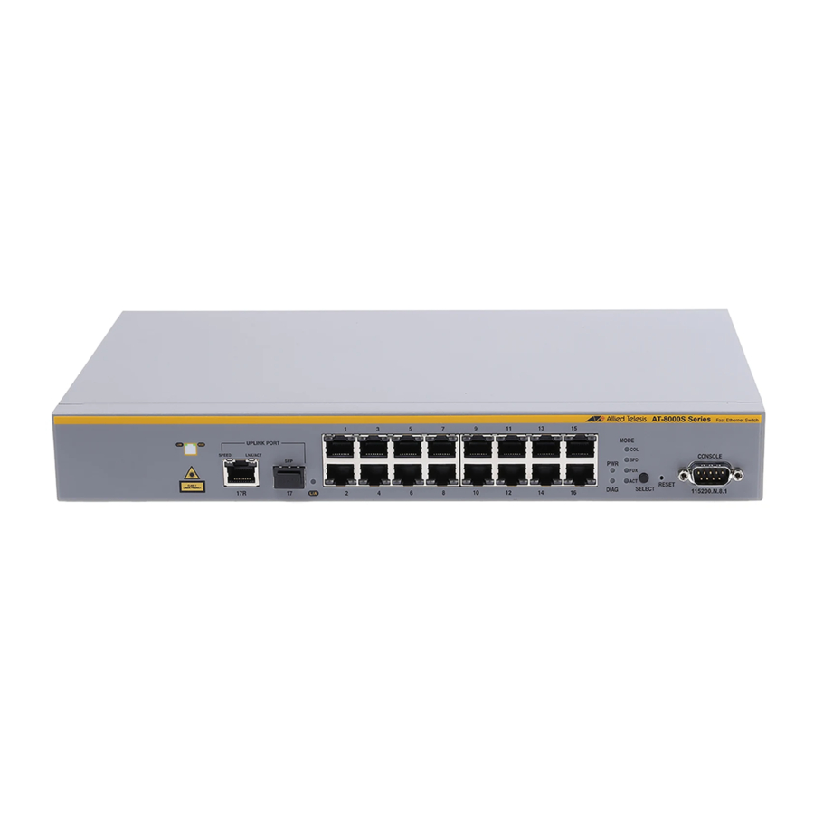
Allied Telesis AT-8000SSwitch Switch Installation Guide AT-8000S/16 Front Panel The following figure illustrates the AT-8000S/16 front panel. Figure 1: AT-8000S/16 Front Panel The AT-8000S/16 front panel is configured as follows: • 16 10/100Mbps Ports — RJ-45 ports designated as 10/100Base-T. The RJ-45 ports are designated as ports Ports 1 - 16. -
Page 11: At-8000S/24 Front Panel
Product Description AT-8000S/24 Front Panel The following figure illustrates the AT-8000S/24 front panel. Figure 3: AT-8000S/24 Front Panel The AT-8000S/24 front panel is configured as follows: • 24 10/100Mbps Ports — RJ-45 ports designated as 10/100Base-T. The RJ-45 ports are designated as ports Ports 1 - 24. -
Page 12: At-8000S/24Poe Front Panel
Allied Telesis AT-8000SSwitch Switch Installation Guide AT-8000S/24POE Front Panel The following figure illustrates the AT-8000S/24POE front panel. Figure 5: AT-8000S/24POE Front Panel The AT-8000S/24POE front panel is configured as follows: • 24 10/100Mbps Ports — RJ-45 ports designated as 10/100Base-T. The RJ-45 ports are designated as ports Ports 1 - 24. -
Page 13: At-8000S/48 Front Panel
Product Description AT-8000S/48 Front Panel The following figure illustrates the AT-8000S/48 front panel. Figure 7: AT-8000S/48 Front Panel The AT-8000S/48 device front panel is configured as follows: • 48 10/100Mbps Ports — RJ-45 ports designated as 10/100Base-T. The RJ-45 ports are designated as ports Ports 1 - 48. -
Page 14: At-8000S/48Poe Front Panel
Allied Telesis AT-8000SSwitch Switch Installation Guide AT-8000S/48POE Front Panel The following figure illustrates the AT-8000S/48POE front panel. Figure 9: AT-8000S/48POE Front Panel The AT-8000S/48 device front panel is configured as follows: • 48 10/100Mbps Ports — RJ-45 ports designated as 10/100Base-T. The RJ-45 ports are designated as ports Ports 1 - 48. -
Page 15: Ports Description
Product Description 10/100Base-T Fast Ethernet Ports Ports Description 10/100Base-T Fast Ethernet Ports The 10/100Base-T Fast Ethernet ports are RJ-45. The 10/100 Mbps port supports half- and full-duplex mode. 10/100/1000Base-T Uplink Ethernet Ports The 24/48 port devices contains two 10/100/100Base-T Gigabit ports, and the 16 port device contains one 10/100/100Base-T port. -
Page 16: Mode Leds
Allied Telesis AT-8000SSwitch Switch Installation Guide Mode LEDs Selecting a particular mode determines what information is displayed on the port LED. For example, if the mode selected is "COL", then the LED on each port indicates the collision status of that port. -
Page 17: Port Leds
Product Description Port LEDs The stacking LED indications are described in the following table: Table 2: Stacking LED Indications LED D e s c r i pt i on LE D I n di c a t i on De s c r i pt i on All LEDs off The device is operating as a standalone switch. - Page 18 Allied Telesis AT-8000SSwitch Switch Installation Guide The RJ-45 ports have two LEDs, one for Link and one for activity (Mode status for non PoE and Load status for PoE). The LED indications are described in the following table: Table 3:...
- Page 19 Product Description Port LEDs The 1000 Base-T/Combo Ethernet RJ-45 ports have two LEDs, one for speed and one for Link and activity. The LED indications are described in the following table: Table 4: Combo Port LED Indications P or t D e s c r i pt i o n LE D I nd ic a t i on D e s c r i p t io n Copper Port Left LED - Speed...
-
Page 20: 24/48 Port Device System Leds
Allied Telesis AT-8000SSwitch Switch Installation Guide 24/48 Port Device System LEDs There are two system LEDs, the Power and Diagnostics LEDs. The following figure illustrates the Power and Diagnostics LEDs. Figure 16: SFP Port LEDs Power LED The PWR LED on the front panel of the device indicates the power supply status. -
Page 21: Stacking Ports Leds
Product Description Stacking Ports LEDs Stacking Ports LEDs The following figure illustrates the Stacking port LEDs. Figure 17: Stacking Port LEDs The RJ-45 ports have two LEDs, one is for link and one is for activity. The Stacking LEDs indications are described in the following table: Table 8: Stacking Ports LEDs Indications... -
Page 22: Installation
Please review the following safety precautions before you begin to install the AT-8000S. Note indicates that a translation of the safety statement is available in a PDF document titled “Translated Safety Statements” on the Allied Telesis website at www.alliedtelesis.com and on the documentation CD shipped with this product. Warning Class 1 Laser product. - Page 23 Installation Preparing for Installation Warning Do not work on equipment or cables during periods of lightning activity. Warning Power cord is used as a disconnection device. To de-energize equipment, disconnect the power cord. Warnings • Class I Equipment. This equipment must be earthed. The power plug must be connected to a properly wired earth grounded socket outlet.
-
Page 24: Site Requirements
Allied Telesis AT-8000S Switch Switch Installation Guide Caution Installation of the equipment in a rack should be such that the amount of air flow required for safe operation of the equipment is not compromised. Warning Reliable earthing of rack-mounted equipment should be maintained. Particular attention should be given to supply connections other than direct connections to the branch circuits (e.g., use of power strips). -
Page 25: Installing The Device
Installation Installing the Device Package Contents While unpacking the device, ensure that the following items are included: • One AT- 8000S/xx series unit • Rubber Feet for desktop installation • Rack-mount kit hardware accessories • An AC power cable • Stacking cable (Yellow color) •... -
Page 26: Rack Installation
Allied Telesis AT-8000S Switch Switch Installation Guide Figure 18: Installing Rubber Feet Set device down on a flat surface, while leaving 2 inches on each side and 5 inches at the back. Ensure that the device has proper ventilation by allowing adequate space for ventilation between the device and the objects around the device. -
Page 27: Connecting The Device
Installation Connecting the Device Figure 19: Attaching the Mounting Brackets Insert the supplied screws into the rack mounting holes and tighten with a screwdriver. Repeat the process for the rack-mounting bracket on the other side of the device. Insert the device into the 19-inch rack and secure the unit to the rack with the rack screws (not provided by the ATI supplier). -
Page 28: Ac Power Connection
Allied Telesis AT-8000S Switch Switch Installation Guide To connect a terminal to the device Console port, perform the following: Connect a cable to the terminal running VT100 terminal emulation software. Ensure that the terminal emulation software is set as follows: a) Select the appropriate port to connect to the device. - Page 29 Installation Connecting the Device Page 29...
-
Page 30: Stacking
Allied Telesis AT-8000SSwitch Installation Guide Chapter 3. Stacking Stacking provides multiple switch management through a single point as if all stack members are a single unit. All stack members are accessed via a single IP address through which the stack is managed. The stack can be managed from the following: •... -
Page 31: Stacking Chain Topology
Stacking Stacking Chain Topology Figure 20: Stacking Ring Topology Most difficulties incurred in Ring topologies occur when a device in the ring becomes non-functional, or a link is severed. In a stack, the system automatically switches to a Stacking Failover topology without any system downtime. -
Page 32: Configuring Stacking
Allied Telesis AT-8000SSwitch Installation Guide Configuring Stacking Configuring stacking is performed during the bootup process. To configure a device as part of a stack, the bootup process must be interrupted straight after the Power On Self Test (POST). To configure the device for stacking, perform the following: Ensure that the device console is connected to a VT100 terminal device or VT100 terminal emulator. - Page 33 Stacking Configuring Stacking The Startup Menu is displayed and contains the following configuration functions: Startup Menu [1] Download Software [2] Erase Flash File [3] Password Recovery Procedure [4] Enter Diagnostic Mode [5] Set Terminal Baud-Rate [6] Stack menu [7] Back Enter your choice or press 'ESC' to exit: From the Startup Menu, press “6”.
-
Page 34: Initial Configuration
Allied Telesis AT-8000SSwitch Installation Guide Chapter 4. Initial Configuration Configuration Overview Before assigning a static IP address to the device, obtain the following information from the network administrator: • A specific IP address allocated by the network administrator for the switch to be configured •... -
Page 35: User Name
Initial Configuration Configuration Note 100.1.1.254 is the IP address of the default gateway that is used to reach the management network 101.101.0.0. To check the configuration, enter the command “show ip interface” as illustrated in the following example. Console# show ip interface Gateway IP Address Activity Status Type... -
Page 36: Troubleshooting
Allied Telesis AT-8000S Switch Installation Guide Chapter 5. Troubleshooting This chapter contains information on how to troubleshoot the switch in the event that a problem occurs. Note If you are still unable to resolve the problem after following the instructions in this chapter, contact ATI Technical Support for assistance. - Page 37 Troubleshooting Page 37...
-
Page 38: Technical Specifications
Allied Telesis AT-8000S Switch Installation Guide Appendix A. Technical Specifications Physical Specifications The different devices have the following physical specifications: • AT-8000S/16 + 1G — 330 x 230.5 x 43.2 mm (W x D x H) • AT-8000S/24 + 2G — 440 x 257 x 43.2 mm (W x D x H) •... -
Page 39: Compliance Standards
Technical Specifications Compliance Standards The devices conform to the following compliance standards: • The Environmental standard, per ATI QLT 1220 • RoHS compliant • The EN50082-1 immunity standard • The following safety standards: – UL1950 – CSA22.2 no.950 – TUV (EN60950) –... - Page 40 Allied Telesis AT-8000S Switch Installation Guide Table 9: RJ-45 Pin Connections for 10/100/1000 Base-T U se TxRx 2+ TxRx 3+ TxRx 3- TxRx 2- TxRx 4+ TxRx 4- Page 40...
- Page 41 Technical Specifications Page 41...
-
Page 42: Safety Statements
Allied Telesis AT-8000SSwitch Installation Guide Appendix B. Safety Statements Important: This appendix contains multiple-language translations for the safety statements in this guide. Wichtig: Dieser Anhang enthält Übersetzungen der in diesem Handbuch enthaltenen Sicherheitshinweise in mehreren Sprachen. Importante: Este apéndice contiene traducciones en múltiples idiomas de los mensajes de seguridad incluidos en esta guía. - Page 43 Safety Statements Electrical Safety Notices Warning 5. Power cord is used as a disconnection device. To de-energize equipment, disconnect the power cord. Warning 6. Class I Equipment. This equipment must be earthed. The power plug must be connected to a properly wired earth grounded socket outlet.
- Page 44 Allied Telesis AT-8000SSwitch Installation Guide Warning 13. Do not strip more than the recommended amount of wire. Stripping more than the recommended amount can create a safety hazard by leaving exposed wire on the terminal block after installation. Warning 14. When installing this equipment, always ensure that the frame ground connection is installed first and disconnected last.
- Page 45 Safety Statements Electrical Safety Notices Warning 23. The power source for the gateway unit should be located near the unit and should be easily accessible. Caution 24. To allow proper cooling of the gateway device, make sure that the air flow around the unit and through its heatsink cooling fins on the rear is not restricted.
- Page 46 31. Use dedicated power circuits or power conditioners to supply reliable electrical power to the device. Warning 32. The chassis may be heavy and awkward to lift. Allied Telesis recommends that you get assistance when mounting the chassis in an equipment rack.
-
Page 47: Telecommunications Compliance Notices
Safety Statements Telecommunications Compliance Notices Caution 39. If installed in a closed or multi-unit rack assembly, the operating ambient temperature of the rack environment may be greater than the room ambient temperature. Therefore, consideration should be given to installing the equipment in an environment compatible with the manufacturer’s maximum rated ambient temperature (Tmra). - Page 48 Allied Telesis AT-8000S Switch Installation Guide Index Port LEDs 15 Power LED 15, 20 Power Specifications 38 Preparing for Installation 22 Numerics Product Description 8 10/100Base-T 15 1000Base-T 15 RJ-45 Port LEDs 17 RS-232 8, 15 AT-8000S/16 10 AT-8000S/24 11...
Need help?
Do you have a question about the AT-8000S Series and is the answer not in the manual?
Questions and answers