Table of Contents
Advertisement
Quick Links
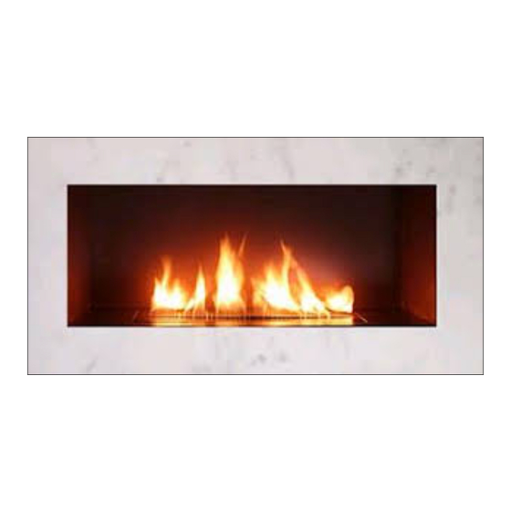
S P A R K M O D E R N F I R E S
OW NER' S O PER AT ION AND IN ST ALL AT ION MANU AL
Z21.60b-2004 /
CSA 2.26b-2004
APPROVED
WARNING: If the information in this
manual is not followed exactly, a fire
or explosion may result causing
property damage, personal inju ry, or
loss of life.
- Installation and service must be performed
by a qualified installer, service agency, or
the gas supplier.
- Do not store or use gasoline or other
flammable vapors and liquids in the vicinity
of this or any other appliance.
- WHAT TO DO IF YOU SMELL GAS:
Do not try to light any appliance.
Do not touch any electrical switch; do not
use any phone in your building.
Immediately call your gas supplier from a
neighbor's
phone.
supplier's instructions.
If you cannot reach your gas supplier, call
the fire department.
NOTE: This appliance is not approved for installation in bedrooms or bathrooms.
RETROFIT FIRE RIBBON
VENTED DECORATIVE APPLIANCE
Follow
the
gas
(IPS)
WARNING:
Improper
alteration, service, or maintenance can cause injury
or property damage. Refer to this manual for
correct installation and operational procedures. For
assistance or additional information consult a
qualified installer, service agency, or gas supplier.
WARNING: This appliance is for install ation only in
a solid-fuel burning masonry or UL127 factory- built
fireplace, constructed of noncombustible material,
and connected to a working flue
minimum flue opening).
WARNING: This is a gas- fired appliance. It uses air
(oxyge n) from the room in which it is installed.
Provisions for adequate combustion and ventila-
tion air must be provided.
INSTALLER: Leave this manual with the appliance.
CONSUMER:Retain this manual for future reference
R eport # 321-L-06b-5
installation,
adjustment,
(see page 4 for
Advertisement
Table of Contents

Related Manuals for Spark modern fires Retrofit Fire Ribbon


Summary of Contents for Spark modern fires Retrofit Fire Ribbon
- Page 1 S P A R K M O D E R N F I R E S RETROFIT FIRE RIBBON VENTED DECORATIVE APPLIANCE (IPS) OW NER’ S O PER AT ION AND IN ST ALL AT ION MANU AL Z21.60b-2004 / CSA 2.26b-2004...
-
Page 2: Safety Information
Make certain you read and under- to smoke, turn off appliance SAFETY stand all warnings. Keep this and call a qualified service INFORMATION manual for reference. It is your person. NOTE: During initial guide to safe and proper operation operation, slight smoking of this Fire Ribbon. -
Page 3: Local Codes
control system and any gas packaging (see Parts List, Make sure that pilot opening control which has been under page 14). is not blocked with media. water. 15. Turn the Ribbon off and let 2. Connect the Burner Assembly 5. Carefully leak test cool... - Page 4 only) or mobile home installation Light a tightly rolled newspaper INSTALLATION must conform with the Standard on the end and place it at the CAN/CSA Z240 Mobile inside front edge of the fireplace. CAUTION: Do not remove Housing, in Canada, or with the Observe the smoke and be sure metal data...
- Page 5 FIREPLACE INSTALLATION CHECK GAS TYPE Use proper gas type for the fireplace you are installing. If you have conflicting gas type, do not install fireplace. See dealer where you purchased the fireplace for proper fireplace for your gas type or conversion kit. INSTALLING GAS PIPING TO FIREPLACE / BURNER SYSTEM LOCATION WARNING A qualified installer or service person must...
- Page 6 FIREPLACE INSTALLATION CAUTION WARNING Only persons licensed to work with gas piping A manual shutoff valve must be installed upstream may make the necessary gas connections to of the appliance. Union tee and plugged " this appliance. NPT pressure tapping point should be installed upstream of the appliance.
- Page 7 FIRE RIBBON RETROFIT BURNER MODEL SPECIFICATIONS BURNER TUBE PILOT MEDIA BURNER TRAY 4" 10" CONTROL ACCESS PANEL see chart below OVERALL HEIGHT = 6" ORIF. SIZE OVERALL FIREPLACE INPUT RATE (BTU/Hr) # ORIF. MODEL # LENGTH (L) WIDTH (min) N.G. L.P.
-
Page 8: Lighting Instruction
LIGHTING INSTRUCTION FOR YOUR SAFETY READ BEFORE OPERATING WARNING If you do not follow these instruction exactly, a fire or explosion may result causing property damage, personal injury or loss of life. A. This appliance is equipped with an ignition device which automatically lights the pilot. Do not try to light the pilot by hand. -
Page 9: Operating Instructions
Continued LIGHTING FOR THE FIRST TIME APPROVED LEAK TESTING METHOD You may check for gas leaks with the following methods only: WARNING • Soap and water solution WARNING • An approved leak testing spray If using a soap and water solution to test •... -
Page 10: To Turn Off Gas To Appliance
Continued TO TURN OFF GAS TO APPLIANCE 1. Turn off all electric power to the appliance if service is to be performed. Unplug 7V DC adapter from the power outlet. 2. If necessary, remove Access Panel from the appliance to access manual shutoff valve on gas line. 3. -
Page 11: Cleaning And Maintenance
CLEANING AND MAINTENANCE WARNING Turn off gas before servicing fireplace. It is recommended that a qualified service technician perform these check-ups at the beginning of each heating season. BURNER, PILOT AND CONTROL COMPARTMENT Keep the control compartment clean by vacuuming or brushing at least twice a year. Make sure the burner porting, pilot air opening and burner air opening are free of obstructions at all times. -
Page 12: Troubleshooting
TROUBLESHOOTING WARNING: Turn off the unit and let cool before servicing. Only a qualified service person should service and repair this appliance. Note: All troubleshooting items are listed in order of operation. OBSERVED PROBLEM POSSIBLE CAUSE REMEDY Unit is smoking / sooting excessively 1. - Page 13 Continued OBSERVED PROBLEM POSSIBLE CAUSE REMEDY When ignitor button is pressed, there is 1. Gas supply turned off or manual shutoff 1. Turn on gas supply or open manual spark at pilot but no ignition valve closed shutoff valve 2. Air in gas lines when installed 2.
-
Page 14: Illustrated Parts List
ILLUSTRATED PARTS LIST SE E NE XT PAGE FOR PART DESCRIPTION 18 18... - Page 15 PARTS LIST This list contains replaceable parts used in your RETROFIT – IPS appliance Part Number according to the Fire Ribbon Model for Natural Gas (and LP) Q-ty Part Description -2’ -3’ -4’ -5’ -6’ -7’ -8’ RETROFIT RETROFIT RETROFIT RETROFIT RETROFIT RETROFIT...
- Page 16 PARTS LIST (CONTINUED) This list contains replaceable parts used in your RETROFIT – IPS appliance Part Number according to the Fire Ribbon Model for Natural Gas (and LP) Q-ty Part Description -2’ -3’ -4’ -5’ -6’ -7’ -8’ RETROFIT RETROFIT RETROFIT RETROFIT RETROFIT...
- Page 17 PARTS LIST (CONTINUED) This list contains replaceable parts used in your RETROFIT– IPS appliance Part Number according to the Fire Ribbon Model for Natural Gas (and LP) Part Description Q-ty -2’ -3’ -4’ -5’ -6’ -7’ -8’ RETROFIT RETROFIT RETROFIT RETROFIT RETROFIT RETROFIT...
-
Page 18: Pilot Assembly
Pilot Assembly 0.199.039 The Remote Control Receiver is a standard feature for Retrofit - IPS appliance. If Wall Thermostat or ON/OFF switch are required for operating, replace the Remote Receiver with desired device using existing wires. Clear contacts (mV rated) to be used. Do not connect to 110V ! -
Page 19: Installation Record
The installer should keep a duplicate of this form for their records. Accurate com- pletion of this form is required for warranty coverage and for any technical support by Spark Modern Fires. Date Purchased:... -
Page 20: Warranty Information
Spark Modern Fires in the appliance are found to be defective in materials or workman- ship, Spark Modern Fires will, at its option, replace or repair the defective components at no charge to the origi- nal owner. Spark Modern Fires will also pay for reasonable labor cost incurred in replacing or repairing such com- ponents for a period of two years from date of installation.
Need help?
Do you have a question about the Retrofit Fire Ribbon and is the answer not in the manual?
Questions and answers